EP0242074B1 - Tageslicht-Röntgenkassette mit einem Gewicht zur Verbesserung der Filmentladung - Google Patents
Tageslicht-Röntgenkassette mit einem Gewicht zur Verbesserung der Filmentladung Download PDFInfo
- Publication number
- EP0242074B1 EP0242074B1 EP87302682A EP87302682A EP0242074B1 EP 0242074 B1 EP0242074 B1 EP 0242074B1 EP 87302682 A EP87302682 A EP 87302682A EP 87302682 A EP87302682 A EP 87302682A EP 0242074 B1 EP0242074 B1 EP 0242074B1
- Authority
- EP
- European Patent Office
- Prior art keywords
- cassette
- weight
- film
- frame
- screen
- Prior art date
- Legal status (The legal status is an assumption and is not a legal conclusion. Google has not performed a legal analysis and makes no representation as to the accuracy of the status listed.)
- Expired
Links
Images
Classifications
-
- G—PHYSICS
- G03—PHOTOGRAPHY; CINEMATOGRAPHY; ANALOGOUS TECHNIQUES USING WAVES OTHER THAN OPTICAL WAVES; ELECTROGRAPHY; HOLOGRAPHY
- G03B—APPARATUS OR ARRANGEMENTS FOR TAKING PHOTOGRAPHS OR FOR PROJECTING OR VIEWING THEM; APPARATUS OR ARRANGEMENTS EMPLOYING ANALOGOUS TECHNIQUES USING WAVES OTHER THAN OPTICAL WAVES; ACCESSORIES THEREFOR
- G03B42/00—Obtaining records using waves other than optical waves; Visualisation of such records by using optical means
- G03B42/02—Obtaining records using waves other than optical waves; Visualisation of such records by using optical means using X-rays
- G03B42/04—Holders for X-ray films
Definitions
- This invention relates to an x-ray cassette. More particularly this invention relates to a daylight x-ray cassette having means for applying a force to a film sheet placed between two substantially flat plates to assist in releasing the film sheet from thereinbetween.
- a film sheet is automatically loaded into the cassette which is operative to hold the film between two opposed substantially parallel x-ray intensifying screens during a period of patient exposure.
- the cassette is unloaded under the influence of gravity using a device as disclosed in the last mentioned patent. This device is adapted to release one of the two cassette plates supporting the intensifying screens to thereby relieve the holding pressure from the film sheet and allow it to drop under the influence of gravity into a light-tight container.
- cantilevered conical actuators have been placed along the cassette edges actuated ty a cam assembly which pivots inwardly of the cassette to thereby edgewise engage the film sheet and buckle it to create a gap between the sheet and a screen.
- the air leakage into the gap tends to equalize the pressure forces on both sides of the sheet to permit it to respond to the influence of gravity and drop from the cassette.
- GB-A-1 362 772 discloses an X-ray film cassette using a movable pressure plate to hold the film in place during use, and able to be retracted to release the film so that it can be ejected.
- the cassette includes an indicator pin which, when it cannot be moved by the operator, confirms the presence of a film sheet in the cassette.
- GB-A-1 362 772 discloses the possibility of the operator using that indicator button to assist ejection of the film.
- the instant invention is an improvement to an X-ray cassette having a frame with inner and outer sides, a pair of plates mounted on the frame and adapted to receive a film-sheet therebetween, with at least one of the plates being movable.
- the cassette defines an opening along a first side of the frame for inserting and removing a film sheet relative to the plates.
- the improvement is set out in the characterising, portion of claim 1.
- the weight may be movable between a first and a second position relative to the first side opening, the first position being closer to the first side opening than the second position.
- the weight may be slidably positioned in the second position.
- the weight may be slidably positioned in the second frame side, or it may be pivotally mounted on the second frame side.
- the weight is preferably 20 grams.
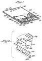
- FIG. 1 a perspective view of an x-ray cassette, generally indicated by reference character 10, with which a buckler assembly 12 is utilized.
- the cassette 10 is formed of a rectangular frame 14 having opposed sides 14S and front or entrance and back sides 14U and 14L, respectively.
- the entrance side 14U includes a slot through which a film sheet may be inserted or retrieved from the cassette.
- a light gate 15 covers the slot when the cassette is closed.
- An opaque but x-ray transparent front or window plate 16 is mounted on the frame 14. The window plate 16 is fixedly mounted to the rectangular frame 14.
- the window plate 16 may be fabricated from magnesium sheet although any suitable material meeting the above specifications, such as aluminum or a synthetic plate comprising an epoxy binder reinforced with a fibrous material such as carbon fibers or Kevlar ® aramid fibers may be employed. Disposed above the window plate 16 is a foam pad 17 and an x-ray intensifying screen 18. A second x-ray intensifying screen 20 is mounted on a backing plate 22 which is movably disposed within the frame 14. A rear plate 23 also mounted on the frame 14 completes the cassette 10. The plates 22 and 23 may be fabricated of aluminum or any other suitable material.
- the sides 14S of the frame 14 define a channel having inner and outer rails 141 and 140, respectively.
- An appropriate number of leaf spring biasing elements 47, 48, 50, to be described in more detail below, are pivotably mounted on the inner rail 141 of the channel sides 14S and extend transversely across the width of the frame 14.
- the leaf spring biasing elements act to support the backing plate 22 and bias it toward the window plate 16.
- Reinforcing tabs 25 may be provided in larger size cassettes to reinforce the backing plate 22.
- a cam rail assembly 28 is slideably received within each of the channels. First and second cam surfaces 30 and 36 are secured to the cam rail assembly 28. Cam surfaces 30 on the cam rail assembly 28 engage and actuate the leaf spring biasing elements to alternately release or urge the moveable backing plate 22 against the window plate 16.
- the cam rail assembly is actuated by external pins (not shown) to more along the frame channels.
- the biasing force imposed by the leaf spring biasing elements on the backing plate is released defining a space between the backing and the window plates, 22, 16 sufficient to allow and x-ray film sheet 32 to be introduced between the two intensifying screens.
- the leaf spring biasing elements urge backing plate 22 towards the window plate 16 to provide intimate contact between the two intensifying screens 18 and 20 and the film sheet 32 sandwiched therebetween.
- Backing plate 22 includes a tab 38 which extends into the channel between inner rail 141 and outer rail 140 through an opening on the side 141 of this channel.
- Tab 38 which may form part of reinforcing tab 25, rides on cam surface 36 urging backing plate away from window plate 16 to open up the space between the intensifying screens.
- the intensifying screens 18 and 20 and the backing plate 22 are provided with notches or cutouts 34 at predetermined locations thereon to facilitate the intrusion of buckler 12 into the film areas.
- a buckler assembly 12 of the type disclosed in De Felice and Le Rous U.S. Patent 4,383,330 is mounted along the sides 14S of the cassette. Bucklers 12 are pivotably mounted on the sides 14S and operatively connected to the cam rail assembly 28. As the cam rail assembly 28 moves from the second position to the first position, a cam surface on the cam rail engages a portion of buckler 12 forcing buckler 12 to extend into cutout 34 and engage the edge of the film sheet contained in the cassette.
- the film sheet is buckled and thereby separated or moved away from the intensifying screen to allow air to seep in the space between the film sheet and the intensifying screen. This speeds the release of the film sheet and reduces the drop out time of the film sheet from the cassette.
- Biasing means not shown, keep the buckler member away from the film sheet when the cam rail assembly 28 is in either the first or the second position.
- Four bucklers as described by De Felice et al. are preferably used to assure reliability of operation.
- the biasing elements 47, 48 and 50 each comprise at least one strap 24 having actuating levers 40 at either end.
- the strap 24 has openings 44 adapted to engage tabs formed on the inner rail 141 of the channel. In this manner, the cam 30 can engage the actuating lever 40.
- the leaf spring elements extending in the plane of the strap are preferably progressively longer and thicker in cross-section as one moves from the edges of the cassette towards its center.
- a biasing element having three different size leaf springs is employed.
- the leaf springs begin at approximately one inch (2.54 cm) from the end of ..strap 24.
- the first set of five leaf springs 47 are 1.53 inches (3:89 cm) long and have a thickness of 0.006 inch (0.152 mm). The distance between each leaf spring is 0.03 inch (0.76 mm).
- a second set of six leaf springs 48 is adjacent to the first set.
- the second series of leaf springs are 2.0 inches (5.08 cm) long and 0.009 inch (0.229 mm) thick.
- a third set of six leaf springs 50 each 2.25 inches (5.72 cm) long and 0.012 inch (0.305 mm) in thickness is used reaching the mid-point of the strap.
- the pattern is then inversely repeated to the end of the strap, the 2.25 inch (5.72 cm) leaf springs followed by the 2.0 inch (5.08 cm) leaf springs followed by the 1.53 inch (3.89 cm) leaf springs terminating 1 inch (2.54 cm) from the other end of the strap 24.
- the force applied onto the backing plate 22 varies along the plate. It is largest in the center portion of the plate as compared to the edges.
- cam surface 30 engages lever arm 40 and a larger force is applied in the center of backing plate 22 preferentially urging the center towards window plate 16.
- the center tends to bow towards window plate 16 and contact is believed to be first established near the center of the plate pushing air away from the center towards the extremities. This is similar to the effect of having a bowed plate as is common in the book type cassettes which prevents air entrapment and results in better contact between the screens and the film.
- a portion of the screen 18 is bent along its edge contiguous the bucklers 12 in a direction away from film sheet 32 and toward the window plate 16.
- the portion of the screen bent towards window plate 16 preferably extends th full length of the sides of the screen adjacent one or both channels 14S.
- the bent angle which is defined as the acute angle between the planes of the screen 18 and the bent edges, being between about 15° and 40°, a preferred range between about 20° and 30°.
- the bent portion of the screen 18 may be formed by compressing the foam pad 17 or the edge of the pad 17 may be tapered or otherwise shaped to fit under the screen.
- the maximum combination of angle and length is such that the underside edge of the screen 18 contacts the surface plate 16. In practical terms this is about 1/16 to 1/8 of an inch (1.588 to 3.175 mm) for an x-ray cassette capable of handling 14 x 17 inches (35.36 x 43.18 cm) film sheets.
- the typical foam pad thickness is about 0.1 inch (0.254 cm).
- the bent portion of screen 18 may extend only partially along the edge adjacent a channel 14S ; so long as one buckler is operating in the cut out along the bent portion, quick release of the film is obtained. It is also desirable that the foam pad 17 be secured along its full surface on back plate 16 and held firmly thereto.
- the screen 20 is mounted on the moveable plate 22 using a layer of adhesive that does not cover the full back surface of the screen.
- the screen is attached to the back plate leaving three 18 mm wide strips extending along side rails 14S and 14L, as explained in more details in the aforementioned US-A-4 688 243.
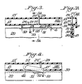
- the lower sides 14L of the rectangular frame comprises a channel having a rectangular cross-section (Fig. 3A).
- the rail of the channel facing inwardly of the cassette is indicated by 13 while the rail of the channel facing outwardly is indicated by 13'.
- the rail 13 there is a slight cutout portion sized to fit the long dimension of a generally rectangularly shaped weight 19.
- This weight which weighs at least 10 grams and preferably about 20 grams, is mounted on rail 13 through the use of 2 pins, pin 21, which is fitted into a hole 26 in rail 13, and pin 29, which is longer, is fitted through holes 27 in rail 13 and 27' in rail 13', extends through the side 14L of the frame to the outside of the cassette.
- the top limit to the weight 19 is determined by the physical space available within the cassette. Obviously too large a weight will bend the film sheet. There is little reason to use weights of more than 30 grams, with 20 grams being preferred as noted.
- the pin 29 serves the dual purpose of supporting and guiding the movement of the weight 19 as well as indicating the presence of a film sheet in the cassette.
- Film indication is achieved when a film sheet 32 is loaded into a cassette. This typically is accomplished when the cassette is positioned with the entrance slot up, i. e., with the opening 31 above the weight 19, under a film dispenser and the film sheet dropped in. The weight 19 drops because of gravity aided by the dropping film sheets impacting the weight 19. This causes the pin 29 to extend and indicate the presence of a film sheet. When pin 29 is in the extended position, an operator may readily know, simply by observation, that a film is in the cassette.
- the intensifying screens 18 and 20 have a small cutout portion 31 along their edge 39.
- this cutout portion generally indicated by the number 31, allows the weight to penetrate the screens a short distance « d which is of the order of 1.588 mm (1/16 inches) in the plane of the intensifying screens.
- a film sheet 32 placed and held between the screens 18 and 20 prevents the weight from entering into that cutout portion 31.
- the weight 19 may slide along the direction of arrow 35 supported on the frame sides rails 13 and 13' by pins 21 and 29.
- the weight 19 rests against the upper edge of a film sheet 32 held between the two intensifying screens 18 and 20.
- two pins actuate the biasing means which hold the two intensifying screens firmly against each other to release and separate them.
- FIG 4 shows an alternate embodiment of this invention in which a pivotably mounted weight 19' is shown.
- This weight is supported through a pivot 37 on the lower side 14L of the cassette.
- a cutout portion 41 on the inner rail 13 of side 14L allows the weight 19 to swing and apply a force in the direction of the arrow 33 on the film sheet 32 held between the intensifying screens 18 and 20.
- a cutout portion 31 is again provided along edge 39 of the intensifing screens.
- a film presence indicator pin 29' is supplied to serve the same purpose as in the embodiment of Figure 3. It may have a flange at the lower end (in the drawing), which is not shown, to limit the pin's motion.
Landscapes
- Physics & Mathematics (AREA)
- General Physics & Mathematics (AREA)
- Radiography Using Non-Light Waves (AREA)
- Apparatus For Radiation Diagnosis (AREA)
Claims (8)
Applications Claiming Priority (2)
| Application Number | Priority Date | Filing Date | Title |
|---|---|---|---|
| US06/850,601 US4712228A (en) | 1986-04-08 | 1986-04-08 | Daylight x-ray cassette having a weight to improve film release |
| US850601 | 1986-04-08 |
Publications (3)
| Publication Number | Publication Date |
|---|---|
| EP0242074A2 EP0242074A2 (de) | 1987-10-21 |
| EP0242074A3 EP0242074A3 (en) | 1987-11-11 |
| EP0242074B1 true EP0242074B1 (de) | 1989-06-28 |
Family
ID=25308606
Family Applications (1)
| Application Number | Title | Priority Date | Filing Date |
|---|---|---|---|
| EP87302682A Expired EP0242074B1 (de) | 1986-04-08 | 1987-03-27 | Tageslicht-Röntgenkassette mit einem Gewicht zur Verbesserung der Filmentladung |
Country Status (7)
| Country | Link |
|---|---|
| US (1) | US4712228A (de) |
| EP (1) | EP0242074B1 (de) |
| JP (1) | JPS62244034A (de) |
| AU (1) | AU591262B2 (de) |
| CA (1) | CA1284739C (de) |
| DE (1) | DE3760289D1 (de) |
| ES (1) | ES2010212B3 (de) |
Families Citing this family (9)
| Publication number | Priority date | Publication date | Assignee | Title |
|---|---|---|---|---|
| US4763346A (en) * | 1986-06-27 | 1988-08-09 | Eastman Kodak Company | Photographic cassette and method of dispensing |
| JPS6420538A (en) * | 1987-07-16 | 1989-01-24 | Toshiba Corp | Radioactive diagnosing device |
| US4813063A (en) * | 1987-11-25 | 1989-03-14 | Eastman Kodak Company | Photographic cassette |
| DE69314382T2 (de) * | 1992-06-02 | 1998-04-30 | Sterling Diagnostic Imaging | Gerät zur Trennung von Film von Röntgenfilmkassetten |
| US5448615A (en) * | 1993-06-30 | 1995-09-05 | Eastman Kodak Company | Film cassette |
| DE69624465T2 (de) * | 1996-04-22 | 2003-08-14 | Agfa-Gevaert, Mortsel | Kassette für photostimulierbare Radiographie |
| US5652781A (en) * | 1996-04-24 | 1997-07-29 | Eastman Kodak Company | Intensifying x-ray film cassette |
| WO2003096119A1 (en) * | 2002-05-07 | 2003-11-20 | Orex Computed Radiography | X-ray cassette with radiation conversion window (mev-kev) and automatic loader |
| US7030404B2 (en) * | 2002-05-28 | 2006-04-18 | Eastman Kodak Company | Methods and apparatus for handling image recording media |
Family Cites Families (17)
| Publication number | Priority date | Publication date | Assignee | Title |
|---|---|---|---|---|
| US28438A (en) * | 1860-05-22 | Adolphus liebenroth | ||
| US3048696A (en) * | 1959-10-29 | 1962-08-07 | Westinghouse Electric Corp | Spotfilm device |
| US3286092A (en) * | 1964-01-24 | 1966-11-15 | Gen Aniline & Film Corp | Radiographic film cassette and film holder with means for automatic unloading of thefilm into a processing apparatus |
| BE795357A (fr) * | 1970-07-07 | 1973-08-13 | Productron Inc | Systeme de manipulation de pellicules a la lumiere du jour et cassette pour pellicules |
| US3934735A (en) * | 1970-07-07 | 1976-01-27 | Productron, Inc. | Daylight film handling system |
| USRE28438E (en) | 1970-07-07 | 1975-06-03 | Ray film package | |
| US3715087A (en) * | 1971-02-18 | 1973-02-06 | Prod Inc | Sheet film storage magazine |
| BR7301068D0 (pt) * | 1972-02-14 | 1973-12-18 | Prodctron Inc | Estojo para placa de filme |
| JPS5245473B2 (de) * | 1972-04-19 | 1977-11-16 | ||
| US3826922A (en) * | 1973-04-09 | 1974-07-30 | American Medical Int Inc | X-ray film cassette holder |
| US3870889A (en) * | 1973-12-26 | 1975-03-11 | Production Inc | Film sheet cassette |
| US4383330A (en) * | 1981-09-28 | 1983-05-10 | E. I. Du Pont De Nemours And Company | X-Ray cassette having quick film release mechanism |
| DE3207328A1 (de) * | 1982-03-01 | 1983-09-08 | Siemens AG, 1000 Berlin und 8000 München | Zielgeraet fuer ein roentgenuntersuchungsgeraet |
| US4444484A (en) * | 1982-08-25 | 1984-04-24 | Eastman Kodak Company | Photographic cassette and dispensing method |
| US4692083A (en) * | 1984-08-22 | 1987-09-08 | E. I. Du Pont De Nemours And Company | Method and apparatus for air jet assisted film unloading from x-ray cassettes |
| US4613984A (en) * | 1984-11-07 | 1986-09-23 | E. I. Du Pont De Nemours And Company | Quick film release x-ray cassette mechanism |
| US4688243A (en) * | 1985-08-21 | 1987-08-18 | E. I. Du Pont De Nemours And Company | Daylight X-ray cassette having variable size leaf springs |
-
1986
- 1986-04-08 US US06/850,601 patent/US4712228A/en not_active Expired - Lifetime
-
1987
- 1987-03-27 DE DE8787302682T patent/DE3760289D1/de not_active Expired
- 1987-03-27 EP EP87302682A patent/EP0242074B1/de not_active Expired
- 1987-03-27 ES ES87302682T patent/ES2010212B3/es not_active Expired
- 1987-04-07 JP JP62085623A patent/JPS62244034A/ja active Granted
- 1987-04-07 AU AU71145/87A patent/AU591262B2/en not_active Ceased
- 1987-04-07 CA CA000534028A patent/CA1284739C/en not_active Expired - Lifetime
Also Published As
| Publication number | Publication date |
|---|---|
| EP0242074A3 (en) | 1987-11-11 |
| CA1284739C (en) | 1991-06-11 |
| AU591262B2 (en) | 1989-11-30 |
| AU7114587A (en) | 1987-10-15 |
| DE3760289D1 (en) | 1989-08-03 |
| US4712228A (en) | 1987-12-08 |
| JPS62244034A (ja) | 1987-10-24 |
| JPH0342650B2 (de) | 1991-06-27 |
| EP0242074A2 (de) | 1987-10-21 |
| ES2010212B3 (es) | 1989-11-01 |
Similar Documents
| Publication | Publication Date | Title |
|---|---|---|
| DE69314382T2 (de) | Gerät zur Trennung von Film von Röntgenfilmkassetten | |
| EP0242074B1 (de) | Tageslicht-Röntgenkassette mit einem Gewicht zur Verbesserung der Filmentladung | |
| EP0198625B1 (de) | Vorrichtung für das automatische Wechseln von Röntgenfilmen | |
| EP0075876B1 (de) | Röntgenfilmkassette mit Mechanismus zur schnellen Entleerung | |
| EP0212624B1 (de) | Tageslichtröntgenkassette mit Blattfedern variabler Grösse | |
| US4434501A (en) | X-Ray film cassette | |
| CA1140601A (en) | Method and device for separating a sheet from a stack of sheets | |
| CA1237011A (en) | Method and apparatus for air jet assisted film unloading from x-ray cassettes | |
| EP0180972B1 (de) | Filmschnellauslösemechanismus für Röntgenkassetten | |
| JP2731607B2 (ja) | シートカバー貼着・剥離装置 | |
| EP0001653A2 (de) | Gerät zum Öffnen und Schliessen von radiographischen Kassetten | |
| US4346300A (en) | Film sheet cassette | |
| EP0000691A2 (de) | Vorrichtung für die Ladung einer Röntgenfilmkassette | |
| US4734926A (en) | X-ray film cassette for daylight system | |
| US4352198A (en) | X-Ray photography cassette | |
| US4198009A (en) | X-ray film cassette | |
| US4260896A (en) | X-ray unit | |
| CA1168074A (en) | X-ray film cassette | |
| EP0000690A1 (de) | Vorrichtung für die Röntgenfotografie | |
| EP0110291B1 (de) | Ausgabevorrichtung für einzelne Blätter | |
| US4362296A (en) | X-Ray film dispensing apparatus | |
| JPS5814345Y2 (ja) | X線装置 | |
| US4813063A (en) | Photographic cassette | |
| CA1122457A (en) | X-ray unit | |
| US4408339A (en) | Compact X-ray unit |
Legal Events
| Date | Code | Title | Description |
|---|---|---|---|
| PUAI | Public reference made under article 153(3) epc to a published international application that has entered the european phase |
Free format text: ORIGINAL CODE: 0009012 |
|
| PUAL | Search report despatched |
Free format text: ORIGINAL CODE: 0009013 |
|
| AK | Designated contracting states |
Kind code of ref document: A2 Designated state(s): BE DE ES FR GB IT |
|
| AK | Designated contracting states |
Kind code of ref document: A3 Designated state(s): BE DE ES FR GB IT |
|
| 17P | Request for examination filed |
Effective date: 19880125 |
|
| 17Q | First examination report despatched |
Effective date: 19880408 |
|
| GRAA | (expected) grant |
Free format text: ORIGINAL CODE: 0009210 |
|
| AK | Designated contracting states |
Kind code of ref document: B1 Designated state(s): BE DE ES FR GB IT |
|
| ITF | It: translation for a ep patent filed | ||
| REF | Corresponds to: |
Ref document number: 3760289 Country of ref document: DE Date of ref document: 19890803 |
|
| ET | Fr: translation filed | ||
| PLBE | No opposition filed within time limit |
Free format text: ORIGINAL CODE: 0009261 |
|
| STAA | Information on the status of an ep patent application or granted ep patent |
Free format text: STATUS: NO OPPOSITION FILED WITHIN TIME LIMIT |
|
| 26N | No opposition filed | ||
| PGFP | Annual fee paid to national office [announced via postgrant information from national office to epo] |
Ref country code: FR Payment date: 19901129 Year of fee payment: 5 |
|
| PGFP | Annual fee paid to national office [announced via postgrant information from national office to epo] |
Ref country code: DE Payment date: 19901205 Year of fee payment: 5 |
|
| PGFP | Annual fee paid to national office [announced via postgrant information from national office to epo] |
Ref country code: BE Payment date: 19901221 Year of fee payment: 5 |
|
| PGFP | Annual fee paid to national office [announced via postgrant information from national office to epo] |
Ref country code: ES Payment date: 19910308 Year of fee payment: 5 |
|
| PGFP | Annual fee paid to national office [announced via postgrant information from national office to epo] |
Ref country code: GB Payment date: 19910318 Year of fee payment: 5 |
|
| ITTA | It: last paid annual fee | ||
| PG25 | Lapsed in a contracting state [announced via postgrant information from national office to epo] |
Ref country code: GB Effective date: 19920327 |
|
| PG25 | Lapsed in a contracting state [announced via postgrant information from national office to epo] |
Ref country code: ES Free format text: LAPSE BECAUSE OF NON-PAYMENT OF DUE FEES Effective date: 19920328 |
|
| PG25 | Lapsed in a contracting state [announced via postgrant information from national office to epo] |
Ref country code: BE Effective date: 19920331 |
|
| BERE | Be: lapsed |
Owner name: E.I. DU PONT DE NEMOURS AND CY Effective date: 19920331 |
|
| GBPC | Gb: european patent ceased through non-payment of renewal fee | ||
| PG25 | Lapsed in a contracting state [announced via postgrant information from national office to epo] |
Ref country code: FR Effective date: 19921130 |
|
| PG25 | Lapsed in a contracting state [announced via postgrant information from national office to epo] |
Ref country code: DE Effective date: 19921201 |
|
| REG | Reference to a national code |
Ref country code: FR Ref legal event code: ST |
|
| REG | Reference to a national code |
Ref country code: ES Ref legal event code: FD2A Effective date: 19990301 |
|
| PG25 | Lapsed in a contracting state [announced via postgrant information from national office to epo] |
Ref country code: IT Free format text: LAPSE BECAUSE OF NON-PAYMENT OF DUE FEES;WARNING: LAPSES OF ITALIAN PATENTS WITH EFFECTIVE DATE BEFORE 2007 MAY HAVE OCCURRED AT ANY TIME BEFORE 2007. THE CORRECT EFFECTIVE DATE MAY BE DIFFERENT FROM THE ONE RECORDED. Effective date: 20050327 |