EP0242049B1 - Sammelbehälter für Kraftstoffdämpfe - Google Patents
Sammelbehälter für Kraftstoffdämpfe Download PDFInfo
- Publication number
- EP0242049B1 EP0242049B1 EP87302083A EP87302083A EP0242049B1 EP 0242049 B1 EP0242049 B1 EP 0242049B1 EP 87302083 A EP87302083 A EP 87302083A EP 87302083 A EP87302083 A EP 87302083A EP 0242049 B1 EP0242049 B1 EP 0242049B1
- Authority
- EP
- European Patent Office
- Prior art keywords
- chamber
- fuel
- bed
- fuel vapour
- purge
- Prior art date
- Legal status (The legal status is an assumption and is not a legal conclusion. Google has not performed a legal analysis and makes no representation as to the accuracy of the status listed.)
- Expired
Links
- 239000000446 fuel Substances 0.000 title claims description 107
- 238000010926 purge Methods 0.000 claims description 72
- 239000007788 liquid Substances 0.000 claims description 31
- 238000001179 sorption measurement Methods 0.000 claims description 7
- 239000000463 material Substances 0.000 claims 1
- OKTJSMMVPCPJKN-UHFFFAOYSA-N Carbon Chemical compound [C] OKTJSMMVPCPJKN-UHFFFAOYSA-N 0.000 description 30
- 239000000203 mixture Substances 0.000 description 25
- 239000002828 fuel tank Substances 0.000 description 7
- 238000010521 absorption reaction Methods 0.000 description 6
- 239000006260 foam Substances 0.000 description 5
- 238000005192 partition Methods 0.000 description 3
- 241001507939 Cormus domestica Species 0.000 description 1
- 230000004048 modification Effects 0.000 description 1
- 238000012986 modification Methods 0.000 description 1
Images

Classifications
-
- F—MECHANICAL ENGINEERING; LIGHTING; HEATING; WEAPONS; BLASTING
- F02—COMBUSTION ENGINES; HOT-GAS OR COMBUSTION-PRODUCT ENGINE PLANTS
- F02M—SUPPLYING COMBUSTION ENGINES IN GENERAL WITH COMBUSTIBLE MIXTURES OR CONSTITUENTS THEREOF
- F02M25/00—Engine-pertinent apparatus for adding non-fuel substances or small quantities of secondary fuel to combustion-air, main fuel or fuel-air mixture
- F02M25/08—Engine-pertinent apparatus for adding non-fuel substances or small quantities of secondary fuel to combustion-air, main fuel or fuel-air mixture adding fuel vapours drawn from engine fuel reservoir
- F02M25/0854—Details of the absorption canister
-
- F—MECHANICAL ENGINEERING; LIGHTING; HEATING; WEAPONS; BLASTING
- F02—COMBUSTION ENGINES; HOT-GAS OR COMBUSTION-PRODUCT ENGINE PLANTS
- F02M—SUPPLYING COMBUSTION ENGINES IN GENERAL WITH COMBUSTIBLE MIXTURES OR CONSTITUENTS THEREOF
- F02M25/00—Engine-pertinent apparatus for adding non-fuel substances or small quantities of secondary fuel to combustion-air, main fuel or fuel-air mixture
- F02M25/08—Engine-pertinent apparatus for adding non-fuel substances or small quantities of secondary fuel to combustion-air, main fuel or fuel-air mixture adding fuel vapours drawn from engine fuel reservoir
- F02M2025/0863—Engine-pertinent apparatus for adding non-fuel substances or small quantities of secondary fuel to combustion-air, main fuel or fuel-air mixture adding fuel vapours drawn from engine fuel reservoir with means dealing with condensed fuel or water, e.g. having a liquid trap
Definitions
- This invention relates to control of fuel vapour released from a fuel tank. More specifically, this invention relates to a fuel vapour storage canister as specified in the preamble of claim 1, for example as disclosed in GB-A 2 035 451.
- the temperature of the vehicle fuel tank rises and falls. As the fuel tank temperature rises, some of the fuel vapour in the space above the liquid level is displaced out of the tank. To avoid releasing the fuel vapour to the atmosphere, an existing system vents the vapour to a canister having a bed that adsorbs and stores the fuel vapour.
- a fuel vapour storage canister according to the present invention is characterised by the features specified in the characterising portion of claim 1.
- This invention provides a canister having an inlet chamber that forms a trap for liquid fuel and that has a purge tube with a small liquid-purge hole at the bottom of the chamber and a large vapour-purge hole spaced above the bottom of the chamber.
- This canister protects its vapour storage bed against absorption of liquid fuel and thereby preserves the bed for adsorption of fuel vapour.
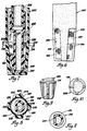
- a fuel vapour storage canister 10 has a bed 12 of activated carbon adapted to adsorb fuel vapour.
- Bed 12 is supported between upper and lower foam screens 14 and 16 within a housing 18 closed by a top 20 and a bottom 22.
- a fuel vapour inlet tube 24 and a purge tube 26 are supported by top 20, extend through bed 12, and open to an inlet chamber 28 below bed 12.
- the upper region of canister 10 is open to the atmosphere through an air vent 30.
- Inlet tube 24 receives a mixture of fuel vapour and air discharged from a fuel tank (not shown). As the mixture passes into chamber 28 and rises through bed 12, the activated carbon in bed 12 adsorbs the fuel vapour and the air flows out through canister vent 30.
- Chamber 28 serves as a trap to capture any liquid fuel that may be present in the mixture of fuel vapour and air received through inlet tube 24. By capturing the liquid fuel before it reaches bed 12, bed 12 is protected against absorption of liquid fuel, and the activated carbon is thereby preserved for adsorption of fuel vapour.
- Fuel is purged from canister 10 by applying vacuum to purge tube 26.
- Purge tube 26 has a small liquid-purge hole 32 at the lower end and a large vapour-purge hole 34 near the top of chamber 28.
- the vacuum applied through vapour-purge hole 34 draws air in through canister vent 30, down through bed 12, and into chamber 28.
- the air flow through bed 12 desorbs the fuel vapour, and the resulting mixture of air and fuel vapour is drawn out through purge tube 26.
- the vacuum applied through liquid-purge hole 32 gradually purges the liquid fuel from chamber 28, and the liquid fuel is drawn out through purge tube 26 along with the mixture of air and fuel vapour.
- a fuel vapour storage canister 110 has a bed 112 of activated carbon adapted to adsorb fuel vapour.
- Bed 112 is supported between upper and lower foam screens 114 and 116 within a housing 118 closed by a top 120 and a bottom 122.
- a fuel vapour inlet tube 124 and a purge tube 126 are supported by top 120, extend through bed 112, and open to an inlet chamber 128 below bed 112.
- the upper region of canister 110 is open to the atmosphere through an air vent 130.
- Inlet tube 124 receives a mixture of fuel vapour and air vented from a fuel tank (not shown). As the mixture passes into chamber 128 and rises through bed 112, the activated carbon in bed 112 adsorbs the fuel vapour and the air flows out through canister vent 130.
- Chamber 128 serves as a trap to capture any liquid fuel that may be present in the mixture of fuel vapour and air received through inlet tube 124. By capturing the liquid fuel before it reaches bed 112, bed 112 is protected against absorption of liquid fuel, and the activated carbon is preserved for adsorption of fuel vapour.
- Fuel is purged from canister 110 by opening a solenoid-operated valve 131 to apply vacuum to purge tube 126.
- Purge tube 126 has a small liquid-purge hole 132 at the lower end and a large vapour-purge hole 134 near the top of chamber 128.
- the vacuum applied through vapour-purge hole 134 draws air in through canister vent 130, down through bed 112, and into chamber 128.
- the air flow through bed 112 desorbs the fuel vapour, and the resulting mixture of air and fuel vapour is drawn out through purge tube 126.
- the vacuum applied through liquid-purge hole 132 gradually purges the liquid fuel from chamber 128, and the liquid fuel is drawn out through purge tube 126 along with the mixture of air and fuel vapour.
- a fuel vapour storage canister 210 has a bed 212 of activated carbon adapted to adsorb fuel vapour.
- Bed 212 is supported between upper and lower foam screens 214 and 216 within a housing 218 closed by a top 220 and a bottom 222.
- a fuel vapour inlet tube 224 and a purge tube 226 are supported by top 220, extend through bed 212, and open to an inlet chamber 228 below bed 212.
- the upper region of canister 210 is open to the atmosphere through an air vent 230.
- Inlet tube 224 extends from an inlet fitting 233 that receives a mixture of fuel vapour and air discharged from a fuel tank (not shown).
- Four windows 235 open from inlet tube 224 to chamber 228; each window is covered by a screen 237 formed of monofilament mesh.
- Chamber 228 serves as a trap to capture any liquid fuel that may be present in the mixture of fuel vapour and air received through inlet tube 224. By capturing the liquid fuel before it reaches bed 212, bed 212 is protected against absorption of liquid fuel, and the activated carbon is thereby preserved for adsorption of fuel vapour.
- Purge tube 226 extends from a purge fitting 238 and is disposed within inlet tube 224.
- Purge tube 226 includes a tip 239 having a flange 241 that engages ribs 243 formed on inlet tube 224 between windows 235; the engagement of flange 241 with ribs 243 provides lateral support for purge tube tip 239.
- Fuel is purged from canister 210 by applying vacuum to purge fitting 238 and purge tube 226.
- Purge tube tip 239 has a small liquid-purge hole 245 about 0.44mm in diameter at the lower end and a large vapour-purge hole 247 about 2.79mm in diameter near the top of chamber 228.
- the vacuum applied through vapour-purge hole 247 draws air through canister vent 230, down through bed 212, and into chamber 228.
- the air flow through bed 212 desorbs the fuel vapour, and the resulting mixture of air and fuel vapour is drawn out through purge tube 226.
- the vacuum applied through liquid-purge hole 245 gradually purges the liquid fuel from chamber 228, and the liquid fuel is drawn out through purge tube 226 along with the mixture of air and fuel vapour.
- Ribs 249 also provide support for lower screen 216.
- housing 218 has a grid 251 spacing upper screen 214 from cover 220 and providing an air chamber between vent 230 and grid 251.
- a fuel vapour storage canister 210' is similar in most respects to canister 210 and includes a bed 212 of activated carbon adapted to adsorb fuel vapour.
- Bed 212 is supported upon a lower foam screen 216' within a housing 218' closed by a bottom 222'.
- Fuel vapour inlet tube 224 and purge tube 226 extend through bed 212 and open to inlet chamber 228 below bed 212.
- Inlet tube 224 receives a mixture of fuel vapour and air and has four windows 235 opening from inlet tube 224 to chamber 228; each window is covered by a screen 237 formed of monofilament mesh. As the mixture passes through inlet tube 224 and windows 235 into chamber 228 and rises through bed 212, the activated carbon in bed 212 adsorbs the fuel vapour.
- Chamber 228 serves as a trap to capture any liquid fuel that may be present in the mixture of fuel vapour and air received through inlet tube 224. By capturing the liquid fuel before it reaches bed 212, bed 212 is protected against absorption of liquid fuel, and the activated carbon is preserved for adsorption of fuel vapour.
- Purge tube 226 is disposed within inlet tube 224.
- Purge tube 226 includes a tip 239 having a flange 241 that engages ribs 243 formed on inlet tube 224 between windows 235.
- Fuel is purged from canister 210' by applying vacuum to purge tube 226.
- Purge tube tip 239 has a small liquid-purge hole 245' about 0.5mm in diameter at the lower end and a large vapour-purge hole 247 about 2.79mm in diameter near the top of chamber 228.
- the vacuum applied through vapour-purge hole 247 draws air down through bed 212 and into chamber 228.
- the air flow through bed 212 desorbs the fuel vapour, and the resulting mixture of air and fuel vapour is drawn out through purge tube 226.
- the vacuum applied through liquid-purge hole 245' gradually purges the liquid fuel from chamber 228, and the liquid fuel is drawn out through purge tube 226 along with the mixture of air and fuel vapour.
- inlet tube 224 is supported laterally by an intermediate grid 248 disposed above ribs 249 formed on bottom 222.
- Grid 248 also provides support for lower screen 216.
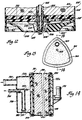
- a fuel vapour storage canister 310 with a horizontal axis has a bed 312 of activated carbon adapted to adsorb fuel vapour.
- Bed 312 is supported between foam screens 314 and 316 within a housing 318.
- housing 318 is closed by a partition 319 and a cover 320.
- a fuel vapour inlet tube 324 and a purge tube 326 are formed as part of cover 320 and open into an inlet chamber 328 between cover 320 and partition 319.
- Chamber 328 opens to bed 312 through an aperture 329 in partition 319, aperture 329 being spaced substantially above the bottom of chamber 328.
- the region 330 at the right end of canister 310 is open to the atmosphere through the vent tube 331 of a cover 331a.
- Inlet tube 324 receives a mixture of fuel vapour and air discharged from a fuel tank (not shown). As the mixture flows through chamber 328, aperture . 329 and bed 312, the activated carbon in bed 312 ado sorbs the fuel vapour and the air flows out through the region 330 and vent tube 331.
- Chamber 328 serves as a trap to capture any liquid fuel that may be present in the mixture of fuel vapour and air received through inlet tube 324. By capturing the liquid fuel before it reaches bed 312, bed 312 is protected against absorption of liquid fuel, and the activated carbon is preserved for adsorption of fuel vapour.
- Fuel is purged from canister 310 by applying vacuum to purge tube 326.
- Purge tube 326 has a small liquid-purge hole 332 about 0.020in (0.5 mm) in diameter at the lower end and a large vapour purge-hole 334 about 0.11 Oin (2.79 mm) in diameter near the top.
- the vacuum applied through vapour-purge hole 334 draws air in through the vent tube 331 and region 330, through bed 312, and into chamber 328.
- the air flow through bed 312 desorbs the fuel vapour, and the resulting mixture of air and fuel vapour is drawn out through purge tube 326.
- the vaccum applied through liquid-purge hole 332 gradually purges the liquid fuel from chamber 328, and the liquid fuel is drawn out through purge tube 326 along with the mixture of air and fuel vapour.
Landscapes
- Engineering & Computer Science (AREA)
- Chemical & Material Sciences (AREA)
- Combustion & Propulsion (AREA)
- Mechanical Engineering (AREA)
- General Engineering & Computer Science (AREA)
- Supplying Secondary Fuel Or The Like To Fuel, Air Or Fuel-Air Mixtures (AREA)
Claims (2)
Applications Claiming Priority (4)
| Application Number | Priority Date | Filing Date | Title |
|---|---|---|---|
| US85154886A | 1986-04-14 | 1986-04-14 | |
| US851548 | 1986-04-14 | ||
| US918886 | 1986-10-15 | ||
| US06/918,886 US4714485A (en) | 1986-04-14 | 1986-10-15 | Fuel vapor storage canister |
Publications (2)
| Publication Number | Publication Date |
|---|---|
| EP0242049A1 EP0242049A1 (de) | 1987-10-21 |
| EP0242049B1 true EP0242049B1 (de) | 1989-07-19 |
Family
ID=27127010
Family Applications (1)
| Application Number | Title | Priority Date | Filing Date |
|---|---|---|---|
| EP87302083A Expired EP0242049B1 (de) | 1986-04-14 | 1987-03-11 | Sammelbehälter für Kraftstoffdämpfe |
Country Status (5)
| Country | Link |
|---|---|
| US (1) | US4714485A (de) |
| EP (1) | EP0242049B1 (de) |
| AU (1) | AU588443B2 (de) |
| CA (1) | CA1275381C (de) |
| DE (1) | DE3760343D1 (de) |
Cited By (2)
| Publication number | Priority date | Publication date | Assignee | Title |
|---|---|---|---|---|
| RU2267027C2 (ru) * | 2004-01-30 | 2005-12-27 | Открытое акционерное общество "АВТОВАЗ" | Адсорбер |
| RU2274765C2 (ru) * | 2004-06-08 | 2006-04-20 | Евгений Васильевич Лысенко | Адсорбер системы улавливания паров топлива |
Families Citing this family (29)
| Publication number | Priority date | Publication date | Assignee | Title |
|---|---|---|---|---|
| JPH0649887Y2 (ja) * | 1988-08-11 | 1994-12-14 | トヨタ自動車株式会社 | 蒸発燃料排出防止装置 |
| US4853009A (en) * | 1988-08-31 | 1989-08-01 | General Motors Corporation | Multi orientation fuel vapor storage canister assembly |
| US5002596A (en) * | 1990-05-21 | 1991-03-26 | Chrysler Corporation | Fuel vapor canister |
| JPH04121450A (ja) * | 1990-09-12 | 1992-04-22 | Toyota Motor Corp | 蒸発燃料処理装置 |
| JPH04247458A (ja) * | 1991-02-01 | 1992-09-03 | Konica Corp | 湿し水不要感光性平版印刷版 |
| JPH04308348A (ja) * | 1991-04-01 | 1992-10-30 | Toyota Motor Corp | 蒸発燃料回収装置 |
| US5304235A (en) * | 1991-04-04 | 1994-04-19 | Toyo Roki Seizo Kabushikikaisha | Canister |
| US5119791A (en) * | 1991-06-07 | 1992-06-09 | General Motors Corporation | Vapor storage canister with liquid trap |
| DE4243816A1 (de) * | 1992-12-23 | 1994-06-30 | Zeolith Tech | Sorptionsmittel-Patrone |
| JPH06280692A (ja) * | 1993-03-25 | 1994-10-04 | Aisan Ind Co Ltd | キャニスタ |
| US5355861A (en) * | 1993-12-07 | 1994-10-18 | Kyosan Denki Co., Ltd. | Evaporative emission control system |
| US5641344A (en) * | 1994-12-05 | 1997-06-24 | Tsuchiya Mfg., Co., Ltd. | Fuel vapor treatment device |
| JP3449008B2 (ja) * | 1995-01-10 | 2003-09-22 | トヨタ自動車株式会社 | キャニスタ |
| USD393471S (en) | 1996-07-02 | 1998-04-14 | Bush Elmer W | Vapor separator |
| RU2120561C1 (ru) * | 1997-04-24 | 1998-10-20 | Электростальское научно-производственное объединение "Неорганика" | Адсорбер топливной системы автомобиля |
| US5910637A (en) | 1997-08-25 | 1999-06-08 | General Motors Corporation | Fuel vapor storage canister |
| US5961699A (en) * | 1998-02-10 | 1999-10-05 | Hyundai Motor Company | Canister apparatus |
| RU2158378C1 (ru) * | 1999-02-16 | 2000-10-27 | Лысенко Евгений Васильевич | Адсорбер |
| US6136075A (en) * | 1999-05-03 | 2000-10-24 | Westvaco Corporation | Automotive evaporative emissions canister adsorptive restraint system |
| RU2176745C2 (ru) * | 2000-03-13 | 2001-12-10 | Лысенко Евгений Васильевич | Адсорбер системы улавливания паров топлива |
| RU2171391C1 (ru) * | 2000-03-14 | 2001-07-27 | Открытое акционерное общество "ЗАРЯ" | Адсорбер улавливания паров бензина в топливной системе автомобилей |
| RU2194185C2 (ru) * | 2000-12-26 | 2002-12-10 | Лысенко Евгений Васильевич | Адсорбер системы улавливания паров топлива |
| KR100505146B1 (ko) * | 2003-04-18 | 2005-08-04 | 코리아에프티 주식회사 | 자동차용 캐니스터 |
| RU2251017C1 (ru) * | 2003-10-02 | 2005-04-27 | Открытое акционерное общество "Счётмаш" | Адсорбер-десорбер |
| RU2301907C1 (ru) * | 2006-02-07 | 2007-06-27 | Открытое акционерное общество "Электростальский химико-механический завод" (ОАО "ЭХМЗ") | Адсорбер улавливания паров бензина |
| RU2330983C1 (ru) * | 2007-02-22 | 2008-08-10 | Открытое акционерное общество "Электростальский химико-механический завод" (ОАО "ЭХМЗ") | Адсорбер улавливания паров бензина |
| RU2377432C1 (ru) * | 2008-04-08 | 2009-12-27 | Открытое акционерное общество "Счетмаш" | Адсорбер-десорбер |
| CN106927120B (zh) * | 2017-04-28 | 2018-10-23 | 广州中臣埃普科技有限公司 | 一种冰浆储存装置、系统及其储存冰浆的方法 |
| US12523190B2 (en) | 2024-05-01 | 2026-01-13 | Phinia Jersey Holdings Llc | Evaporative emissions canister with liquid-fuel-resistant adsorbent |
Family Cites Families (23)
| Publication number | Priority date | Publication date | Assignee | Title |
|---|---|---|---|---|
| US3352294A (en) * | 1965-07-28 | 1967-11-14 | Exxon Research Engineering Co | Process and device for preventing evaporation loss |
| US3393669A (en) * | 1966-05-19 | 1968-07-23 | Exxon Research Engineering Co | Apparatus and process for adsorbing and desorbing internal combustion engine fuel vapors |
| DE1751160A1 (de) * | 1967-06-21 | 1971-05-13 | Esso Res And Engineering Co | Kraftstoffsystem |
| GB1217347A (en) * | 1967-06-21 | 1970-12-31 | Exxon Research Engineering Co | Fuel system for an internal combustion engine |
| US3515107A (en) * | 1968-05-31 | 1970-06-02 | Calgon C0Rp | Two-bed evaporative loss control device |
| DE1927046A1 (de) * | 1969-05-28 | 1970-12-10 | Porsche Kg | Einrichtung zum Abscheiden von Brennstoff aus der aus dem Brennstoffversorgungssystem einer Brennkraftmaschine austretenden Luft |
| US3618578A (en) * | 1969-08-01 | 1971-11-09 | British Motor Corp Ltd | Motor vehicle fuel systems |
| US3575152A (en) * | 1969-10-01 | 1971-04-20 | Gen Motors Corp | Vapor recovery using a plurality of progressively absorbent beds connected in series |
| US3646731A (en) * | 1970-09-02 | 1972-03-07 | Ford Motor Co | Air cleaner and fuel vapor storage assembly remotely associated with an engine |
| GB1316161A (en) * | 1970-10-16 | 1973-05-09 | Chrysler Uk | Fuel tanks |
| US3854911A (en) * | 1971-04-13 | 1974-12-17 | B Walker | Pressure fuel tank evaporation control |
| US3730158A (en) * | 1971-07-28 | 1973-05-01 | Gen Motors Corp | Canister for evaporation loss control |
| US3698061A (en) * | 1971-08-13 | 1972-10-17 | Western Electric Co | Apparatus for forming and testing electrical components |
| US4058380A (en) * | 1973-03-02 | 1977-11-15 | Ford Motor Company | Carbon cell |
| US3903858A (en) * | 1973-04-23 | 1975-09-09 | Stearns C Wayne | Crankcase fumes treatment |
| CA1124594A (en) * | 1978-11-30 | 1982-06-01 | Brian W. Green | Engine with evaporation control system |
| US4203401A (en) * | 1979-01-29 | 1980-05-20 | General Motors Corporation | Evaporative emissions canister |
| JPS5922066B2 (ja) * | 1979-03-08 | 1984-05-24 | 日産自動車株式会社 | 内燃機関の蒸発燃料処理装置 |
| US4280466A (en) * | 1979-03-26 | 1981-07-28 | General Motors Corporation | Evaporative emission control device |
| US4326489A (en) * | 1979-12-27 | 1982-04-27 | Ford Motor Company | Proportional flow fuel vapor purge control device |
| CA1156887A (en) * | 1980-06-18 | 1983-11-15 | Syozo Yanagisawa | Vaporized fuel adsorbing canister |
| JPS57126127A (en) * | 1981-01-27 | 1982-08-05 | Toshiba Corp | Diffusion treating method for semiconductor wafer |
| US4478619A (en) * | 1983-05-02 | 1984-10-23 | Arends Andrew G | Compressed air filtering apparatus |
-
1986
- 1986-10-15 US US06/918,886 patent/US4714485A/en not_active Expired - Lifetime
-
1987
- 1987-03-11 EP EP87302083A patent/EP0242049B1/de not_active Expired
- 1987-03-11 DE DE8787302083T patent/DE3760343D1/de not_active Expired
- 1987-03-19 CA CA000532397A patent/CA1275381C/en not_active Expired - Lifetime
- 1987-03-31 AU AU70919/87A patent/AU588443B2/en not_active Ceased
Cited By (2)
| Publication number | Priority date | Publication date | Assignee | Title |
|---|---|---|---|---|
| RU2267027C2 (ru) * | 2004-01-30 | 2005-12-27 | Открытое акционерное общество "АВТОВАЗ" | Адсорбер |
| RU2274765C2 (ru) * | 2004-06-08 | 2006-04-20 | Евгений Васильевич Лысенко | Адсорбер системы улавливания паров топлива |
Also Published As
| Publication number | Publication date |
|---|---|
| US4714485A (en) | 1987-12-22 |
| AU7091987A (en) | 1987-10-15 |
| DE3760343D1 (en) | 1989-08-24 |
| CA1275381C (en) | 1990-10-23 |
| EP0242049A1 (de) | 1987-10-21 |
| AU588443B2 (en) | 1989-09-14 |
Similar Documents
| Publication | Publication Date | Title |
|---|---|---|
| EP0242049B1 (de) | Sammelbehälter für Kraftstoffdämpfe | |
| EP0242048B1 (de) | Sammelbehälter für Kraftstoffdämpfe | |
| US4750465A (en) | Fuel vapor storage canister | |
| US4852761A (en) | In tank vapor storage canister | |
| US5119791A (en) | Vapor storage canister with liquid trap | |
| US7294179B2 (en) | Canister of vehicle | |
| US4403587A (en) | Fuel evaporative emission control apparatus for vehicles | |
| US5878729A (en) | Air control valve assembly for fuel evaporative emission storage canister | |
| US4306894A (en) | Canister for fuel evaporative emission control systems | |
| CA1151030A (en) | Proportional flow fuel vapor purge control device | |
| US5207808A (en) | Canister for adsorbing evaporated fuel | |
| US4338106A (en) | Canister for fuel evaporative emission control system | |
| US4507132A (en) | Fuel evaporation preventing device | |
| US3831353A (en) | Fuel vapor control device | |
| US4693393A (en) | Fuel vapor storage canister having tortuous vent passage | |
| JPH08189428A (ja) | 内燃機関用蒸発燃料処理装置 | |
| JPH10325369A (ja) | キャニスタ | |
| US4430099A (en) | Vaporized fuel adsorbing canister | |
| US4703736A (en) | Fuel vapor containment device | |
| US7353809B2 (en) | Evaporative emissions canister with integral liquid fuel trap | |
| GB2339848A (en) | Evaporative emission canister for an automotive vehicle | |
| EP0719384A1 (de) | Aktivkohlefilter für kraftfahrzeuge | |
| JPS62265460A (ja) | 燃料蒸気貯蔵キヤニスタ | |
| JPS6119827B2 (de) | ||
| JPH08158958A (ja) | 蒸発燃料の処理装置 |
Legal Events
| Date | Code | Title | Description |
|---|---|---|---|
| PUAI | Public reference made under article 153(3) epc to a published international application that has entered the european phase |
Free format text: ORIGINAL CODE: 0009012 |
|
| 17P | Request for examination filed |
Effective date: 19870318 |
|
| AK | Designated contracting states |
Kind code of ref document: A1 Designated state(s): DE FR GB IT SE |
|
| 17Q | First examination report despatched |
Effective date: 19880503 |
|
| GRAA | (expected) grant |
Free format text: ORIGINAL CODE: 0009210 |
|
| ITF | It: translation for a ep patent filed | ||
| AK | Designated contracting states |
Kind code of ref document: B1 Designated state(s): DE FR GB IT SE |
|
| REF | Corresponds to: |
Ref document number: 3760343 Country of ref document: DE Date of ref document: 19890824 |
|
| ET | Fr: translation filed | ||
| PLBE | No opposition filed within time limit |
Free format text: ORIGINAL CODE: 0009261 |
|
| STAA | Information on the status of an ep patent application or granted ep patent |
Free format text: STATUS: NO OPPOSITION FILED WITHIN TIME LIMIT |
|
| 26N | No opposition filed | ||
| ITTA | It: last paid annual fee | ||
| EAL | Se: european patent in force in sweden |
Ref document number: 87302083.8 |
|
| PGFP | Annual fee paid to national office [announced via postgrant information from national office to epo] |
Ref country code: SE Payment date: 20010326 Year of fee payment: 15 |
|
| REG | Reference to a national code |
Ref country code: GB Ref legal event code: IF02 |
|
| PG25 | Lapsed in a contracting state [announced via postgrant information from national office to epo] |
Ref country code: SE Free format text: LAPSE BECAUSE OF NON-PAYMENT OF DUE FEES Effective date: 20020312 |
|
| EUG | Se: european patent has lapsed |
Ref document number: 87302083.8 |
|
| PGFP | Annual fee paid to national office [announced via postgrant information from national office to epo] |
Ref country code: GB Payment date: 20030310 Year of fee payment: 17 |
|
| PGFP | Annual fee paid to national office [announced via postgrant information from national office to epo] |
Ref country code: FR Payment date: 20030313 Year of fee payment: 17 |
|
| PG25 | Lapsed in a contracting state [announced via postgrant information from national office to epo] |
Ref country code: GB Free format text: LAPSE BECAUSE OF NON-PAYMENT OF DUE FEES Effective date: 20040311 |
|
| GBPC | Gb: european patent ceased through non-payment of renewal fee |
Effective date: 20040311 |
|
| PG25 | Lapsed in a contracting state [announced via postgrant information from national office to epo] |
Ref country code: FR Free format text: LAPSE BECAUSE OF NON-PAYMENT OF DUE FEES Effective date: 20041130 |
|
| REG | Reference to a national code |
Ref country code: FR Ref legal event code: ST |
|
| PG25 | Lapsed in a contracting state [announced via postgrant information from national office to epo] |
Ref country code: IT Free format text: LAPSE BECAUSE OF NON-PAYMENT OF DUE FEES Effective date: 20050311 |
|
| PGFP | Annual fee paid to national office [announced via postgrant information from national office to epo] |
Ref country code: DE Payment date: 20050530 Year of fee payment: 19 |
|
| PG25 | Lapsed in a contracting state [announced via postgrant information from national office to epo] |
Ref country code: DE Free format text: LAPSE BECAUSE OF NON-PAYMENT OF DUE FEES Effective date: 20061003 |