EP0241970A1 - Verfahren und Einrichtung zur Entfaltung einer Hülle um ein Objekt, insbesondere um einen Satelliten - Google Patents
Verfahren und Einrichtung zur Entfaltung einer Hülle um ein Objekt, insbesondere um einen Satelliten Download PDFInfo
- Publication number
- EP0241970A1 EP0241970A1 EP87200559A EP87200559A EP0241970A1 EP 0241970 A1 EP0241970 A1 EP 0241970A1 EP 87200559 A EP87200559 A EP 87200559A EP 87200559 A EP87200559 A EP 87200559A EP 0241970 A1 EP0241970 A1 EP 0241970A1
- Authority
- EP
- European Patent Office
- Prior art keywords
- envelope
- pole
- internal
- balloon
- poles
- Prior art date
- Legal status (The legal status is an assumption and is not a legal conclusion. Google has not performed a legal analysis and makes no representation as to the accuracy of the status listed.)
- Granted
Links
Images


Classifications
-
- B—PERFORMING OPERATIONS; TRANSPORTING
- B64—AIRCRAFT; AVIATION; COSMONAUTICS
- B64G—COSMONAUTICS; VEHICLES OR EQUIPMENT THEREFOR
- B64G1/00—Cosmonautic vehicles
- B64G1/22—Parts of, or equipment specially adapted for fitting in or to, cosmonautic vehicles
- B64G1/222—Parts of, or equipment specially adapted for fitting in or to, cosmonautic vehicles for deploying structures between a stowed and deployed state
- B64G1/2221—Parts of, or equipment specially adapted for fitting in or to, cosmonautic vehicles for deploying structures between a stowed and deployed state characterised by the manner of deployment
- B64G1/2227—Inflating
Definitions
- the invention relates to a method for developing a waterproof envelope around an object. It extends to a device allowing the implementation of this process.
- the present invention proposes to indicate a method for automatically developing a waterproof envelope around an object, in particular an object subjected to relatively low aerodynamic forces, such as a satellite in orbital phase.
- Another objective of the invention is to allow the realization of a rigid structure, radially around an object.
- Another objective is to provide a device of small bulk and reduced weight, easily transportable for the implementation of the above method.
- on-board inflation means can be used, the capacity of which is, for example, calculated so as to allow the state of fullness of the envelope to be obtained.
- the method preferably consists in the prior phase: - to use an envelope, called internal, of elongated shape, having two poles opposite to each of its ends, to roll up said envelope on itself and to fold it longitudinally in accordion in this rolled up position, - to secure the pole of the envelope located in the upturned part on the object and to connect the other pole of the envelope to said object by means of a connecting mast of length less than said envelope, lying in its folded position.
- This envelope and the connecting mast can therefore be initially integrated inside a container guaranteeing their protection.
- only one area of the object is condemned by the presence of the folded envelope and it is therefore possible to intervene on it until the development of this envelope.
- This outer envelope allows to release a much larger volume around the object.
- it allows the creation of a protected volume whose object is the center, this volume being accessible from all the faces of this object.
- the rupture of the internal envelope is generally permitted by the use of an envelope of cylindrical shape surrounded by a network of circumferential reinforcements distributed over the height of the latter so as to give it a lobed structure.
- the lobes of the envelope tear allowing rapid inflation of the external envelope without the need for high pressure gas jets.
- the connecting mast can also consist of an elongated balloon having a pole fixed to the object and a pole common to the common poles of the inner and outer envelopes. It should be noted the primordial importance of this connecting balloon which, by its presence, makes it possible to obtain the form of equilibrium of the internal envelope, rolled up, in which it is developed around the object. Indeed, without the presence of the connection balloon, this internal envelope would deploy entirely in the extension of the object.
- This connection balloon is preferably of cylindrical elongated shape and is provided with a network of circumferential reinforcements.
- This large-volume structure can in particular constitute a workspace of which a satellite happens to be the central core and provide working conditions sheltered from various external aggressions.
- the poles of this envelope can be connected to two opposite faces of the object by means of two rigid masts, capable of working in compression and in tension, and thereby ensuring the resumption of forces. requesting the structure produced.
- the present invention extends to a device intended to be secured to an object for the implementation of the method described above; this device comprises a container intended to be secured to said object and containing: - a connecting mast having one end secured to the container and adapted to be able to have two extreme positions: . a folded position where it is folded back inside the container, .
- a deployed position where it extends outside the container, - a first envelope, called internal, cylindrical having a pole secured to the container and a pole secured to the end of the connecting mast, said internal casing being folded in accordion fashion in the container in an upturned position, - A second envelope, called external envelope, partially threaded around the internal envelope, before folding thereof and having an open annular pole secured to the peripheral wall of said inner envelope and a pole secured to the end of the mast liaison, - Inflation means adapted to allow the successive inflation of the internal envelope and the external envelope.
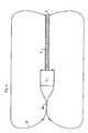
- This process requires, first, a balloon 2, said connecting balloon, which is made by assembling rectangular time, by any known process, such as for example described in French Patent Application No. 80.00343 in the name of the applicant, along their straight edges.
- This balloon thus has a cylindrical portion which is extended by gathered pleated portions whose edges are attached to pole pieces 3 and 4 arranged at the poles of the balloon on the axis thereof.
- the constituent material is an airtight composite material, having, for example, a polyester weft arranged in the circumferential direction and a "Kevlar" warp arranged in the longitudinal direction. It therefore has a higher asymmetric resistance in the longitudinal direction only in the circumferential direction.
- This balloon is surrounded by a network of circumferential reinforcements 5 and a network of longitudinal reinforcements 6.
- Each of these reinforcements is made of an inextensible material of high resistance, for example "Kevlar”.
- pole pieces 3 and 4 are joined by an inextensible interpolar link 7 extending along the axis of the balloon; this link 7 can also consist of a bundle of bands made of an inextensible material of high resistance, in particular "Kevlar".
- the method requires, for its implementation, an envelope 8, said internal envelope of volume and length greater than the volume of the connection balloon 2.
- This first envelope 8 is manufactured in a similar manner to the connection balloon by assembly of rectangular time zones. These spindles are joined together and fixed, at one of their ends, to one of the pole pieces 3 of the connection balloon 2 and at their opposite end to another pole piece 9.
- This first envelope 8 has the same structure as the connection balloon 2 except for the interpolar link 7 which is deleted.
- the method requires a second casing 10, called the outer casing, of volume greater than the first casing 8.
- This casing 10 is also manufactured in a similar manner to the connection balloon 2 by assembling rectangular spindles.
- This external envelope 10 is partially threaded around the internal envelope 8; one of the ends of the spindles making it up is then fixed to the pole piece 3 common to the connection balloon 2 and to the internal envelope 8.
- This outer envelope 10 is then pleated longitudinally until the opposite end of the spindles is at a distance from the poles 3, 9 of the internal envelope 8 opposite a circumferential reinforcement zone 11 of this internal envelope.
- the end of the spindles is then fixed on this reinforced zone 11 by any known means such as sewing or thermocellage; the assembly is finally reinforced by means of circumferential reinforcements 12, such as kevlar cables, which provide hooping of this assembly.
- connection balloon 2 and the inner 8 and outer 10 envelopes are then integrated inside a container 13; the respective poles 4, 9 of the connection balloon 2 and of the internal envelope 8 are in turn secured to one of the walls of this container 13.
- container is meant to define any compartment suitable for housing the connection balloon and the two envelopes. It is understood that this compartment may consist of a separate element intended to be fixed on the object or of an element, such as a hold, formed directly inside this object.
- connection balloon 2 These inflation means are provided with supply means communicating with the interior of the connection balloon 2 and which allow admission of compressed air coming from a turbo-compressor (or any other equivalent means) through a duct.
- control means make it possible to measure the relative pressure inside the connection balloon 2.
- These control means are adapted to generate, for a given set pressure, the triggering of a sequencer which controls the closing of the conduit supplying the connection tank 2 and the opening of a branch conduit communicating with the interior of the internal envelope 8.
- connection balloon 2 and the two envelopes 8, 10 are housed in the deflated state inside the container 13 intended to be secured to one face of the object 1.
- One of the poles 4, 9 of the connection balloon 2 and respectively of the internal envelope 8 is, as mentioned above, secured to one of the walls of the container 13.
- this container 13 which also contains the inflation means, is of relatively small dimensions and weight, given the small size of the various envelopes in their deflated state.
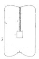
- the inflation means allow, initially, the inflation of the connecting mast 2 until it obtains its state of fullness where it is developed in the extension of the object 1. In this state of fullness, this connecting ball 2 keeps the common pole 3 of the inner 8 and outer 10 envelopes away from the object 1 ( Figure 2).
- the sequencer associated with the inflation means cuts the air supply to this balloon 2 and activates the filling of the internal envelope 8.
- the part of the internal envelope 8 located in the extension of the object 1 initially inflates, until its state of fullness. Secondly, by its upturned position and the presence of the connection balloon 2, this internal envelope 8 develops along the object 1 and finally in the extension of the face of this object. opposite the connecting ball 2.
- section of this internal envelope 8 must be larger than that of the object, so as to allow it to slide along this object 1.
- this connecting ball 2 gives this assembly good rigidity in traction and in bending. It should be noted that this connecting balloon 2 can be replaced by a rigid, retractable connecting mast.
- the final structure obtained is therefore a radial structure developed around the object.
- this volume is accessible from all sides of the object.
- the external envelope 10 of this structure can also be stiffened by using a double-walled envelope and by injecting a stiffening foam in the interval between these two walls.
Landscapes
- Engineering & Computer Science (AREA)
- Remote Sensing (AREA)
- Aviation & Aerospace Engineering (AREA)
- Tents Or Canopies (AREA)
- Folding Of Thin Sheet-Like Materials, Special Discharging Devices, And Others (AREA)
- Aerials With Secondary Devices (AREA)
Applications Claiming Priority (2)
| Application Number | Priority Date | Filing Date | Title |
|---|---|---|---|
| FR8605097A FR2596727B1 (fr) | 1986-04-08 | 1986-04-08 | Procede et dispositif pour developper une enveloppe autour d'un objet notamment un satellite |
| FR8605097 | 1986-04-08 |
Publications (2)
| Publication Number | Publication Date |
|---|---|
| EP0241970A1 true EP0241970A1 (de) | 1987-10-21 |
| EP0241970B1 EP0241970B1 (de) | 1989-07-05 |
Family
ID=9334080
Family Applications (1)
| Application Number | Title | Priority Date | Filing Date |
|---|---|---|---|
| EP87200559A Expired EP0241970B1 (de) | 1986-04-08 | 1987-03-24 | Verfahren und Einrichtung zur Entfaltung einer Hülle um ein Objekt, insbesondere um einen Satelliten |
Country Status (6)
| Country | Link |
|---|---|
| US (1) | US4770374A (de) |
| EP (1) | EP0241970B1 (de) |
| DE (1) | DE3760294D1 (de) |
| ES (1) | ES2009833B3 (de) |
| FR (1) | FR2596727B1 (de) |
| GR (1) | GR3000127T3 (de) |
Cited By (1)
| Publication number | Priority date | Publication date | Assignee | Title |
|---|---|---|---|---|
| US5156361A (en) * | 1988-08-16 | 1992-10-20 | Lang Mark S | Modular space station |
Families Citing this family (9)
| Publication number | Priority date | Publication date | Assignee | Title |
|---|---|---|---|---|
| US6213430B1 (en) * | 1999-01-05 | 2001-04-10 | Trw Inc. | Vehicle launch system having an acoustic insulator |
| US6786456B2 (en) * | 2002-08-29 | 2004-09-07 | L'garde, Inc. | Deployable inflatable boom and methods for packaging and deploying a deployable inflatable boom |
| US7204460B2 (en) * | 2004-06-24 | 2007-04-17 | Bigelow Aerospace | Orbital debris shield |
| US7780118B2 (en) * | 2004-07-29 | 2010-08-24 | Bigelow Aerospace | Radiation shield |
| US7401752B2 (en) * | 2004-09-14 | 2008-07-22 | The Boeing Company | Protective shield assembly for space optics and associated methods |
| FR2903626B1 (fr) * | 2006-07-12 | 2008-10-10 | Eads Space Transp Sas Soc Par | Assemblage de preimpregnes pour la realisation de structures par exemple a deploiement par gonflage |
| US8070105B2 (en) * | 2007-12-14 | 2011-12-06 | The United States Of America As Represented By The Administrator Of The National Aeronautics And Space Administration | Inflatable nested toroid structure |
| CN106516164A (zh) * | 2016-12-24 | 2017-03-22 | 哈尔滨工业大学 | 一种有序展开的柔性充气支撑臂 |
| WO2025071688A2 (en) * | 2023-05-23 | 2025-04-03 | Trans Astronautica Corporation | Systems and methods for capturing space objects |
Citations (4)
| Publication number | Priority date | Publication date | Assignee | Title |
|---|---|---|---|---|
| US4166598A (en) * | 1974-05-30 | 1979-09-04 | The United States Of America As Represented By The Secretary Of The Air Force | Vehicle enshrouding apparatus |
| US4166597A (en) * | 1974-05-09 | 1979-09-04 | The United States Of America As Represented By The Secretary Of The Air Force | Stowable and inflatable vehicle |
| US4314682A (en) * | 1969-02-24 | 1982-02-09 | Rockwell International Corporation | Deployable shield |
| US4504031A (en) * | 1979-11-01 | 1985-03-12 | The Boeing Company | Aerodynamic braking and recovery method for a space vehicle |
Family Cites Families (1)
| Publication number | Priority date | Publication date | Assignee | Title |
|---|---|---|---|---|
| FR1485587A (fr) * | 1966-03-22 | 1967-06-23 | Dispositif permettant d'améliorer l'atterrissage sur un satellite et en particuliersur la lune |
-
1986
- 1986-04-08 FR FR8605097A patent/FR2596727B1/fr not_active Expired
-
1987
- 1987-03-24 DE DE8787200559T patent/DE3760294D1/de not_active Expired
- 1987-03-24 EP EP87200559A patent/EP0241970B1/de not_active Expired
- 1987-03-24 ES ES87200559T patent/ES2009833B3/es not_active Expired
- 1987-04-07 US US07/035,576 patent/US4770374A/en not_active Expired - Fee Related
-
1989
- 1989-08-21 GR GR89400145T patent/GR3000127T3/el unknown
Patent Citations (4)
| Publication number | Priority date | Publication date | Assignee | Title |
|---|---|---|---|---|
| US4314682A (en) * | 1969-02-24 | 1982-02-09 | Rockwell International Corporation | Deployable shield |
| US4166597A (en) * | 1974-05-09 | 1979-09-04 | The United States Of America As Represented By The Secretary Of The Air Force | Stowable and inflatable vehicle |
| US4166598A (en) * | 1974-05-30 | 1979-09-04 | The United States Of America As Represented By The Secretary Of The Air Force | Vehicle enshrouding apparatus |
| US4504031A (en) * | 1979-11-01 | 1985-03-12 | The Boeing Company | Aerodynamic braking and recovery method for a space vehicle |
Cited By (1)
| Publication number | Priority date | Publication date | Assignee | Title |
|---|---|---|---|---|
| US5156361A (en) * | 1988-08-16 | 1992-10-20 | Lang Mark S | Modular space station |
Also Published As
| Publication number | Publication date |
|---|---|
| ES2009833B3 (es) | 1989-10-16 |
| EP0241970B1 (de) | 1989-07-05 |
| US4770374A (en) | 1988-09-13 |
| FR2596727A1 (fr) | 1987-10-09 |
| FR2596727B1 (fr) | 1988-06-10 |
| GR3000127T3 (en) | 1990-11-29 |
| DE3760294D1 (en) | 1989-08-10 |
Similar Documents
| Publication | Publication Date | Title |
|---|---|---|
| EP1966064B1 (de) | Verbesserter ventilbeutel | |
| EP0241970B1 (de) | Verfahren und Einrichtung zur Entfaltung einer Hülle um ein Objekt, insbesondere um einen Satelliten | |
| WO1986003469A1 (fr) | Ballon aerostatique pilotable | |
| EP0031981B1 (de) | Verfahren zur Herstellung einer Raumballonhülle, hergestellte Hülle und deren Verwendung in der Raumfahrt | |
| EP1873061B1 (de) | Entfaltbare Struktur, die starre Elemente umfasst und auf einem Raumflugkörper untergebracht ist | |
| EP1468910B1 (de) | Faltbarer und ausfahrbarer Satz von Elementen in einem Raumfahrzeug | |
| FR2990770A1 (fr) | Procede et systeme de recuperation pour des flutes marines de capteur de recherche geophysique marine | |
| FR2491862A1 (fr) | Systeme de gonflage pour radeau de sauvetage, radeau de sauvetage equipe d'un tel systeme et procede de montage d'un tel systeme sur un radeau | |
| FR2772814A1 (fr) | Voute gonflable, deployable et escamotable | |
| EP0091841B1 (de) | Zusatzvorrichtung für die Düse eines Raketenmotors | |
| EP1960265B1 (de) | In der luft transportierbarer tank zur lagerung eines im flug abzuwerfenden produkts | |
| EP0033020B1 (de) | Verfahren und Vorrichtung zum Starten und Aufblasen eines Raumfahrballons | |
| FR2578508A1 (fr) | Brassiere de sauvetage gonflable | |
| CA2370052C (fr) | Dispositif pneumatique flottant, notamment radeau pneumatique de survie, equipe de moyens de gonflage a venturi | |
| FR2683305A1 (fr) | Perfectionnement aux systemes comprenant un element allonge deployable a fonction pyrotechnique. | |
| EP0401891B1 (de) | Luftballon, bestimmt zur selbständigen und umsteuerbaren Bewegung zwischen dem Boden eines Planeten mit einer Atmosphäre und einer vorherbestimmten Höhe | |
| FR2877315A1 (fr) | Dispositif de commande du deploiement de structures gonflables | |
| FR2780819A1 (fr) | Reflecteur d'antenne elastiquement deformable pour engin spatial | |
| CA2323714C (fr) | Dispositif pour le deploiement sur le sol d'un revetement de surface provisoire stocke enroule | |
| FR2723718A1 (fr) | Aile ou voilure d'ultra leger motorise pendulaire a depliage et repliage rapide et d'encombrement reduit. | |
| FR2841533A1 (fr) | Dispositif de protection contre les chocs, notamment d'un vehicule de transport | |
| FR2724350A1 (fr) | Sac de retenue a gonflage peripherique, pour vehicule | |
| WO2025040398A1 (fr) | Structure gonflable pliable | |
| EP4399147A1 (de) | Vorrichtung zum schutz eines schiffsrumpfes mit einem aufblasbaren kotflügelelement | |
| FR2522613A1 (fr) | Dispositif pour la protection provisoire d'une charge portee par une fusee |
Legal Events
| Date | Code | Title | Description |
|---|---|---|---|
| PUAI | Public reference made under article 153(3) epc to a published international application that has entered the european phase |
Free format text: ORIGINAL CODE: 0009012 |
|
| AK | Designated contracting states |
Kind code of ref document: A1 Designated state(s): BE CH DE ES FR GB GR IT LI LU NL |
|
| 17P | Request for examination filed |
Effective date: 19871120 |
|
| 17Q | First examination report despatched |
Effective date: 19880817 |
|
| GRAA | (expected) grant |
Free format text: ORIGINAL CODE: 0009210 |
|
| AK | Designated contracting states |
Kind code of ref document: B1 Designated state(s): BE CH DE ES FR GB GR IT LI LU NL |
|
| REF | Corresponds to: |
Ref document number: 3760294 Country of ref document: DE Date of ref document: 19890810 |
|
| ITF | It: translation for a ep patent filed | ||
| GBT | Gb: translation of ep patent filed (gb section 77(6)(a)/1977) | ||
| PLBE | No opposition filed within time limit |
Free format text: ORIGINAL CODE: 0009261 |
|
| STAA | Information on the status of an ep patent application or granted ep patent |
Free format text: STATUS: NO OPPOSITION FILED WITHIN TIME LIMIT |
|
| REG | Reference to a national code |
Ref country code: GR Ref legal event code: FG4A Free format text: 3000127 |
|
| 26N | No opposition filed | ||
| ITTA | It: last paid annual fee | ||
| EPTA | Lu: last paid annual fee | ||
| PGFP | Annual fee paid to national office [announced via postgrant information from national office to epo] |
Ref country code: LU Payment date: 19960301 Year of fee payment: 10 |
|
| PGFP | Annual fee paid to national office [announced via postgrant information from national office to epo] |
Ref country code: GR Payment date: 19960305 Year of fee payment: 10 |
|
| PGFP | Annual fee paid to national office [announced via postgrant information from national office to epo] |
Ref country code: ES Payment date: 19960311 Year of fee payment: 10 |
|
| PGFP | Annual fee paid to national office [announced via postgrant information from national office to epo] |
Ref country code: BE Payment date: 19960313 Year of fee payment: 10 |
|
| PGFP | Annual fee paid to national office [announced via postgrant information from national office to epo] |
Ref country code: GB Payment date: 19960322 Year of fee payment: 10 |
|
| PGFP | Annual fee paid to national office [announced via postgrant information from national office to epo] |
Ref country code: FR Payment date: 19960326 Year of fee payment: 10 |
|
| PGFP | Annual fee paid to national office [announced via postgrant information from national office to epo] |
Ref country code: NL Payment date: 19960328 Year of fee payment: 10 |
|
| PGFP | Annual fee paid to national office [announced via postgrant information from national office to epo] |
Ref country code: CH Payment date: 19960409 Year of fee payment: 10 |
|
| PGFP | Annual fee paid to national office [announced via postgrant information from national office to epo] |
Ref country code: DE Payment date: 19960525 Year of fee payment: 10 |
|
| PG25 | Lapsed in a contracting state [announced via postgrant information from national office to epo] |
Ref country code: LU Free format text: LAPSE BECAUSE OF NON-PAYMENT OF DUE FEES Effective date: 19970324 Ref country code: GB Effective date: 19970324 |
|
| PG25 | Lapsed in a contracting state [announced via postgrant information from national office to epo] |
Ref country code: ES Free format text: LAPSE BECAUSE OF NON-PAYMENT OF DUE FEES Effective date: 19970325 |
|
| PG25 | Lapsed in a contracting state [announced via postgrant information from national office to epo] |
Ref country code: LI Effective date: 19970331 Ref country code: CH Effective date: 19970331 Ref country code: BE Effective date: 19970331 |
|
| BERE | Be: lapsed |
Owner name: CENTRE NATIONAL D'ETUDES SPATIALES CNES ETABLISSE Effective date: 19970331 |
|
| PG25 | Lapsed in a contracting state [announced via postgrant information from national office to epo] |
Ref country code: GR Free format text: THE PATENT HAS BEEN ANNULLED BY A DECISION OF A NATIONAL AUTHORITY Effective date: 19970930 |
|
| PG25 | Lapsed in a contracting state [announced via postgrant information from national office to epo] |
Ref country code: NL Effective date: 19971001 |
|
| REG | Reference to a national code |
Ref country code: GR Ref legal event code: MM2A Free format text: 3000127 |
|
| GBPC | Gb: european patent ceased through non-payment of renewal fee |
Effective date: 19970324 |
|
| REG | Reference to a national code |
Ref country code: CH Ref legal event code: PL |
|
| PG25 | Lapsed in a contracting state [announced via postgrant information from national office to epo] |
Ref country code: FR Free format text: LAPSE BECAUSE OF NON-PAYMENT OF DUE FEES Effective date: 19971128 |
|
| NLV4 | Nl: lapsed or anulled due to non-payment of the annual fee |
Effective date: 19971001 |
|
| PG25 | Lapsed in a contracting state [announced via postgrant information from national office to epo] |
Ref country code: DE Effective date: 19971202 |
|
| REG | Reference to a national code |
Ref country code: FR Ref legal event code: ST |
|
| REG | Reference to a national code |
Ref country code: ES Ref legal event code: FD2A Effective date: 19990201 |
|
| PG25 | Lapsed in a contracting state [announced via postgrant information from national office to epo] |
Ref country code: IT Free format text: LAPSE BECAUSE OF NON-PAYMENT OF DUE FEES;WARNING: LAPSES OF ITALIAN PATENTS WITH EFFECTIVE DATE BEFORE 2007 MAY HAVE OCCURRED AT ANY TIME BEFORE 2007. THE CORRECT EFFECTIVE DATE MAY BE DIFFERENT FROM THE ONE RECORDED. Effective date: 20050324 |