EP0241970A1 - Method and device to develop a casing round an article, especially a satellite - Google Patents
Method and device to develop a casing round an article, especially a satellite Download PDFInfo
- Publication number
- EP0241970A1 EP0241970A1 EP87200559A EP87200559A EP0241970A1 EP 0241970 A1 EP0241970 A1 EP 0241970A1 EP 87200559 A EP87200559 A EP 87200559A EP 87200559 A EP87200559 A EP 87200559A EP 0241970 A1 EP0241970 A1 EP 0241970A1
- Authority
- EP
- European Patent Office
- Prior art keywords
- envelope
- pole
- internal
- balloon
- poles
- Prior art date
- Legal status (The legal status is an assumption and is not a legal conclusion. Google has not performed a legal analysis and makes no representation as to the accuracy of the status listed.)
- Granted
Links
- 238000000034 method Methods 0.000 title claims abstract description 33
- 230000002787 reinforcement Effects 0.000 claims description 16
- 230000006378 damage Effects 0.000 claims description 4
- 230000002093 peripheral effect Effects 0.000 claims description 4
- 239000006260 foam Substances 0.000 claims description 3
- 230000006835 compression Effects 0.000 claims description 2
- 238000007906 compression Methods 0.000 claims description 2
- 229920000271 Kevlar® Polymers 0.000 description 4
- 239000004761 kevlar Substances 0.000 description 4
- 239000000463 material Substances 0.000 description 3
- 206010001488 Aggression Diseases 0.000 description 1
- 230000016571 aggressive behavior Effects 0.000 description 1
- 238000012550 audit Methods 0.000 description 1
- 238000005452 bending Methods 0.000 description 1
- 238000006243 chemical reaction Methods 0.000 description 1
- 239000002131 composite material Substances 0.000 description 1
- 239000000470 constituent Substances 0.000 description 1
- 230000006866 deterioration Effects 0.000 description 1
- 230000008030 elimination Effects 0.000 description 1
- 238000003379 elimination reaction Methods 0.000 description 1
- 229920000728 polyester Polymers 0.000 description 1
- 238000009958 sewing Methods 0.000 description 1
Images


Classifications
-
- B—PERFORMING OPERATIONS; TRANSPORTING
- B64—AIRCRAFT; AVIATION; COSMONAUTICS
- B64G—COSMONAUTICS; VEHICLES OR EQUIPMENT THEREFOR
- B64G1/00—Cosmonautic vehicles
- B64G1/22—Parts of, or equipment specially adapted for fitting in or to, cosmonautic vehicles
- B64G1/222—Parts of, or equipment specially adapted for fitting in or to, cosmonautic vehicles for deploying structures between a stowed and deployed state
- B64G1/2221—Parts of, or equipment specially adapted for fitting in or to, cosmonautic vehicles for deploying structures between a stowed and deployed state characterised by the manner of deployment
- B64G1/2227—Inflating
Definitions
- the invention relates to a method for developing a waterproof envelope around an object. It extends to a device allowing the implementation of this process.
- the present invention proposes to indicate a method for automatically developing a waterproof envelope around an object, in particular an object subjected to relatively low aerodynamic forces, such as a satellite in orbital phase.
- Another objective of the invention is to allow the realization of a rigid structure, radially around an object.
- Another objective is to provide a device of small bulk and reduced weight, easily transportable for the implementation of the above method.
- on-board inflation means can be used, the capacity of which is, for example, calculated so as to allow the state of fullness of the envelope to be obtained.
- the method preferably consists in the prior phase: - to use an envelope, called internal, of elongated shape, having two poles opposite to each of its ends, to roll up said envelope on itself and to fold it longitudinally in accordion in this rolled up position, - to secure the pole of the envelope located in the upturned part on the object and to connect the other pole of the envelope to said object by means of a connecting mast of length less than said envelope, lying in its folded position.
- This envelope and the connecting mast can therefore be initially integrated inside a container guaranteeing their protection.
- only one area of the object is condemned by the presence of the folded envelope and it is therefore possible to intervene on it until the development of this envelope.
- This outer envelope allows to release a much larger volume around the object.
- it allows the creation of a protected volume whose object is the center, this volume being accessible from all the faces of this object.
- the rupture of the internal envelope is generally permitted by the use of an envelope of cylindrical shape surrounded by a network of circumferential reinforcements distributed over the height of the latter so as to give it a lobed structure.
- the lobes of the envelope tear allowing rapid inflation of the external envelope without the need for high pressure gas jets.
- the connecting mast can also consist of an elongated balloon having a pole fixed to the object and a pole common to the common poles of the inner and outer envelopes. It should be noted the primordial importance of this connecting balloon which, by its presence, makes it possible to obtain the form of equilibrium of the internal envelope, rolled up, in which it is developed around the object. Indeed, without the presence of the connection balloon, this internal envelope would deploy entirely in the extension of the object.
- This connection balloon is preferably of cylindrical elongated shape and is provided with a network of circumferential reinforcements.
- This large-volume structure can in particular constitute a workspace of which a satellite happens to be the central core and provide working conditions sheltered from various external aggressions.
- the poles of this envelope can be connected to two opposite faces of the object by means of two rigid masts, capable of working in compression and in tension, and thereby ensuring the resumption of forces. requesting the structure produced.
- the present invention extends to a device intended to be secured to an object for the implementation of the method described above; this device comprises a container intended to be secured to said object and containing: - a connecting mast having one end secured to the container and adapted to be able to have two extreme positions: . a folded position where it is folded back inside the container, .
- a deployed position where it extends outside the container, - a first envelope, called internal, cylindrical having a pole secured to the container and a pole secured to the end of the connecting mast, said internal casing being folded in accordion fashion in the container in an upturned position, - A second envelope, called external envelope, partially threaded around the internal envelope, before folding thereof and having an open annular pole secured to the peripheral wall of said inner envelope and a pole secured to the end of the mast liaison, - Inflation means adapted to allow the successive inflation of the internal envelope and the external envelope.
- This process requires, first, a balloon 2, said connecting balloon, which is made by assembling rectangular time, by any known process, such as for example described in French Patent Application No. 80.00343 in the name of the applicant, along their straight edges.
- This balloon thus has a cylindrical portion which is extended by gathered pleated portions whose edges are attached to pole pieces 3 and 4 arranged at the poles of the balloon on the axis thereof.
- the constituent material is an airtight composite material, having, for example, a polyester weft arranged in the circumferential direction and a "Kevlar" warp arranged in the longitudinal direction. It therefore has a higher asymmetric resistance in the longitudinal direction only in the circumferential direction.
- This balloon is surrounded by a network of circumferential reinforcements 5 and a network of longitudinal reinforcements 6.
- Each of these reinforcements is made of an inextensible material of high resistance, for example "Kevlar”.
- pole pieces 3 and 4 are joined by an inextensible interpolar link 7 extending along the axis of the balloon; this link 7 can also consist of a bundle of bands made of an inextensible material of high resistance, in particular "Kevlar".
- the method requires, for its implementation, an envelope 8, said internal envelope of volume and length greater than the volume of the connection balloon 2.
- This first envelope 8 is manufactured in a similar manner to the connection balloon by assembly of rectangular time zones. These spindles are joined together and fixed, at one of their ends, to one of the pole pieces 3 of the connection balloon 2 and at their opposite end to another pole piece 9.
- This first envelope 8 has the same structure as the connection balloon 2 except for the interpolar link 7 which is deleted.
- the method requires a second casing 10, called the outer casing, of volume greater than the first casing 8.
- This casing 10 is also manufactured in a similar manner to the connection balloon 2 by assembling rectangular spindles.
- This external envelope 10 is partially threaded around the internal envelope 8; one of the ends of the spindles making it up is then fixed to the pole piece 3 common to the connection balloon 2 and to the internal envelope 8.
- This outer envelope 10 is then pleated longitudinally until the opposite end of the spindles is at a distance from the poles 3, 9 of the internal envelope 8 opposite a circumferential reinforcement zone 11 of this internal envelope.
- the end of the spindles is then fixed on this reinforced zone 11 by any known means such as sewing or thermocellage; the assembly is finally reinforced by means of circumferential reinforcements 12, such as kevlar cables, which provide hooping of this assembly.
- connection balloon 2 and the inner 8 and outer 10 envelopes are then integrated inside a container 13; the respective poles 4, 9 of the connection balloon 2 and of the internal envelope 8 are in turn secured to one of the walls of this container 13.
- container is meant to define any compartment suitable for housing the connection balloon and the two envelopes. It is understood that this compartment may consist of a separate element intended to be fixed on the object or of an element, such as a hold, formed directly inside this object.
- connection balloon 2 These inflation means are provided with supply means communicating with the interior of the connection balloon 2 and which allow admission of compressed air coming from a turbo-compressor (or any other equivalent means) through a duct.
- control means make it possible to measure the relative pressure inside the connection balloon 2.
- These control means are adapted to generate, for a given set pressure, the triggering of a sequencer which controls the closing of the conduit supplying the connection tank 2 and the opening of a branch conduit communicating with the interior of the internal envelope 8.
- connection balloon 2 and the two envelopes 8, 10 are housed in the deflated state inside the container 13 intended to be secured to one face of the object 1.
- One of the poles 4, 9 of the connection balloon 2 and respectively of the internal envelope 8 is, as mentioned above, secured to one of the walls of the container 13.
- this container 13 which also contains the inflation means, is of relatively small dimensions and weight, given the small size of the various envelopes in their deflated state.
- the inflation means allow, initially, the inflation of the connecting mast 2 until it obtains its state of fullness where it is developed in the extension of the object 1. In this state of fullness, this connecting ball 2 keeps the common pole 3 of the inner 8 and outer 10 envelopes away from the object 1 ( Figure 2).
- the sequencer associated with the inflation means cuts the air supply to this balloon 2 and activates the filling of the internal envelope 8.
- the part of the internal envelope 8 located in the extension of the object 1 initially inflates, until its state of fullness. Secondly, by its upturned position and the presence of the connection balloon 2, this internal envelope 8 develops along the object 1 and finally in the extension of the face of this object. opposite the connecting ball 2.
- section of this internal envelope 8 must be larger than that of the object, so as to allow it to slide along this object 1.
- this connecting ball 2 gives this assembly good rigidity in traction and in bending. It should be noted that this connecting balloon 2 can be replaced by a rigid, retractable connecting mast.
- the final structure obtained is therefore a radial structure developed around the object.
- this volume is accessible from all sides of the object.
- the external envelope 10 of this structure can also be stiffened by using a double-walled envelope and by injecting a stiffening foam in the interval between these two walls.
Abstract
L'invention concerne un procédé pour développer une enveloppe étanche (8) autour d'un objet (1). Ce procédé consiste à utiliser une enveloppe, de forme allongée cylindrique, ayant deux pôles (3, 9) opposés, à chacune de ses extrémités, à retrousser cette enveloppe sur elle-même et à la plier longitudinalement, en accordéon, dans cette position retroussée. Le pôle (9) de cette enveloppe (8) se trouvant dans la partie retroussée est ensuite solidarisé sur l'objet (1). Le pôle (3) opposé est quant à lui relié à l'objet (1) par l'intermédiaire d'un mât de liaison (2) constitué d'un ballon de forme cylindrique se trouvant initialement à l'état dégonflé. Le développement, proprement dit de l'enveloppe (8), consiste à gonfler le mât de liaison jusqu'à son état de plénitude, puis à gonfler l'enveloppe (8) jusqu'à son état de plénitude où elle se trouve développée autour de l'objet (1).The invention relates to a method for developing a sealed envelope (8) around an object (1). This process consists in using an envelope, of elongated cylindrical shape, having two opposite poles (3, 9), at each of its ends, to roll up this envelope on itself and to fold it longitudinally, in accordion, in this rolled up position . The pole (9) of this envelope (8) located in the upturned part is then secured to the object (1). The opposite pole (3) is connected to the object (1) by means of a connecting mast (2) consisting of a cylindrical balloon which is initially in the deflated state. The development, properly speaking of the envelope (8), consists in inflating the connecting mast to its state of fullness, then in inflating the envelope (8) until its state of fullness where it is developed around of the object (1).
Description
L'invention concerne un procédé permettant de développer une enveloppe étanche autour d'un objet. Elle s'étend à un dispositif permettant la mise en oeuvre de ce procédé.The invention relates to a method for developing a waterproof envelope around an object. It extends to a device allowing the implementation of this process.
Actuellement, lorsqu'on envisage le déploiement d'une enveloppe liée à une structure par un de ses pôles, ce déploiement est réalisé de façon que cette enveloppe s'étende en totalité dans le prolongement de cette structure. Ainsi, seule la face de la structure liée au pôle se trouve protégée par cette enveloppe. De la même manière, l'accès éventuel à l'intérieur du volume délimité par cette enveloppe ne peut se faire qu'à partir d'une seule face de la structure.Currently, when considering the deployment of an envelope linked to a structure by one of its poles, this deployment is carried out so that this envelope extends entirely in the extension of this structure. Thus, only the face of the structure linked to the pole is protected by this envelope. Likewise, any access to the interior of the volume delimited by this envelope can only be done from one side of the structure.
La présente invention se propose d'indiquer un procédé permettant de développer automatiquement une enveloppe étanche autour d'un objet, notamment un objet soumis à des forces aérodynamiques relativement faibles, tel qu'un satellite en phase orbitale.The present invention proposes to indicate a method for automatically developing a waterproof envelope around an object, in particular an object subjected to relatively low aerodynamic forces, such as a satellite in orbital phase.
Un autre objectif de l'invention est de permettre la réalisation d'une structure rigide, radialement autour d'un objet.Another objective of the invention is to allow the realization of a rigid structure, radially around an object.
Un autre objectif est de fournir un dispositif de faible encombrement et de poids réduit, facilement transportable en vue de la mise en oeuvre du procédé précité.Another objective is to provide a device of small bulk and reduced weight, easily transportable for the implementation of the above method.
Le procédé conforme à l'invention pour le développement d'une enveloppe étanche autour d'un objet consiste :
- (a) dans une phase préalable :
- à envelopper l'objet d'une enveloppe étanche se présentant à l'état dégonflé,
- à relier une zone, dite pôle, de cette enveloppe avec l'objet par l'intermédiaire d'un mât de liaison susceptible de pouvoir présenter deux positions extrêmes :
. une position repliée où il maintient le pôle de l'enveloppe sensiblement contre l'objet,
. une position déployée où il maintient le pôle de l'enveloppe, à distance, en regard de l'objet,
. ledit mât de liaison se trouvant initialement dans sa position repliée, - (b) dans une phase ultérieure de développement :
. à engendrer le déploiement du mât entre sa position repliée et sa position déployée,
. à gonfler l'enveloppe jusqu'à l'obtention de son état de plénitude.
- (a) in a preliminary phase:
- to wrap the object in a sealed envelope in the deflated state,
- to connect a zone, called pole, of this envelope with the object by means of a connecting mast capable of being able to present two extreme positions:
. a folded position where it maintains the pole of the envelope substantially against the object,
. a deployed position where it maintains the pole of the envelope, at a distance, facing the object,
. said connecting mast being initially in its folded position, - (b) in a later phase of development:
. to generate the deployment of the mast between its folded position and its deployed position,
. inflating the envelope until it reaches its fullness state.
Ce procédé permet donc de déployer à tout moment et automatiquement une enveloppe étanche autour d'un objet. Dans ce but, il peut être utilisé des moyens embarqués de gonflage dont la capacité est, par exemple, calculée de façon à permettre l'obtention de l'état de plénitude de l'enveloppe.This process therefore makes it possible to deploy a waterproof envelope around an object at any time and automatically. For this purpose, on-board inflation means can be used, the capacity of which is, for example, calculated so as to allow the state of fullness of the envelope to be obtained.
En outre, dans cet état de plénitude, l'enveloppe se trouve centrée sur l'objet grâce à la présence du mât de liaison, et ses réactions sont par conséquent les mêmes que celles de l'objet.In addition, in this state of fullness, the envelope is centered on the object thanks to the presence of the connecting mast, and its reactions are therefore the same as those of the object.
Toutefois, afin de permettre d'accéder à l'objet et d'éviter la détérioration de l'enveloppe avant la phase de développement, le procédé consiste préférentiellement dans la phase préalable :
- à utiliser une enveloppe, dite interne, de forme allongée, ayant deux pôles opposés à chacune de ses extrémités, à retrousser ladite enveloppe sur elle-même et à la plier longitudinalement en accordéon dans cette position retroussée,
- à solidariser le pôle de l'enveloppe se trouvant dans la partie retroussée sur l'objet et à relier l'autre pôle de l'enveloppe audit objet par l'intermédiaire d'un mât de liaison de longueur inférieure à ladite enveloppe, se trouvant dans sa position repliée.However, in order to allow access to the object and to avoid deterioration of the envelope before the development phase, the method preferably consists in the prior phase:
- to use an envelope, called internal, of elongated shape, having two poles opposite to each of its ends, to roll up said envelope on itself and to fold it longitudinally in accordion in this rolled up position,
- to secure the pole of the envelope located in the upturned part on the object and to connect the other pole of the envelope to said object by means of a connecting mast of length less than said envelope, lying in its folded position.
L'utilisation d'une enveloppe retroussée sur elle-même puis pliée longitudinalement en accordéon, permet de la déployer autour de l'objet alors qu'initialement cette enveloppe se trouve intégralement positionnée d'un seul côté de cet objet.The use of an envelope rolled up on itself then folded longitudinally in accordion, makes it possible to deploy it around the object whereas initially this envelope is entirely positioned on only one side of this object.
Cette enveloppe et le mât de liaison peuvent donc être initialement intégrés à l'intérieur d'un container garantissant leur protection. En outre, une seule zone de l'objet se trouve condamnée par la présence de l'enveloppe repliée et il est donc possible d'intervenir sur celui-ci jusqu'au moment du développement de cette enveloppe.This envelope and the connecting mast can therefore be initially integrated inside a container guaranteeing their protection. In addition, only one area of the object is condemned by the presence of the folded envelope and it is therefore possible to intervene on it until the development of this envelope.
Il convient de noter que ce développement ne peut être commandé que lorsque les forces aérodynamiques auxquelles est soumis l'objet sont relativement faibles. Ceci est notamment le cas pour un satellite se trouvant en phase orbitale, ou un engin circulant à faible altitude au-dessus de la surface terrestre.It should be noted that this development can only be controlled when the aerodynamic forces to which the object is subjected are relatively low. This is particularly the case for a satellite in the orbital phase, or a machine circulating at low altitude above the earth's surface.
L'enveloppe interne utilisée est préférentiellement une enveloppe de forme générale allongée cylindrique ayant une section de taille supérieure à celle de l'objet de façon à permettre son coulissement le long de l'objet. En outre, selon une autre caractéristique de l'invention, cette enveloppe peut être associée à une deuxième enveloppe, le procédé consistant alors :
- (a) dans la phase préalable :
- à utiliser une deuxième enveloppe, dite externe, de volume supérieur, à l'enveloppe interne et possédant un pôle ouvert de forme annulaire,
- à enfiler partiellement, en la plissant, l'enveloppe externe autour de l'enveloppe interne, avant pliage de celle-ci, de façon que le pôle annulaire de ladite enveloppe externe soit fixé sur la périphérie de l'enveloppe interne à distance de ses pôles, l'autre pôle de l'enveloppe externe étant commun au pôle de l'enveloppe interne destiné à être fixé sur le mât de liaison,
- à retrousser, puis à plier ensemble longitudinalement en accordéon les deux enveloppes ainsi associées,
- à solidariser un des pôles de l'enveloppe interne sur l'objet et à relier le pôle commun des enveloppes interne et externe audit objet par l'intermédiaire du mât de liaison se trouvant dans sa position repliée, - (b) dans la phase de développement :
. à engendrer le déploiement du mât de liaison,
. à gonfler l'enveloppe interne jusqu'à son état de plénitude où elle se trouve développée autour de l'objet,
. à poursuivre le gonflage jusqu'à rupture de la paroi périphérique extérieure de l'enveloppe interne,
. à gonfler l'enveloppe externe jusqu'à son état de plénitude.
- (a) in the preliminary phase:
to use a second envelope, called an external envelope, of greater volume, than the internal envelope and having an open pole of annular shape,
- to partially thread, by pleating, the external envelope around the internal envelope, before folding thereof, so that the annular pole of said external envelope is fixed on the periphery of the internal envelope at a distance from its poles, the other pole of the external envelope being common to the pole of the internal envelope intended to be fixed on the connecting mast,
- to roll up, then to fold longitudinally in accordion the two envelopes thus associated,
- to secure one of the poles of the internal envelope to the object and to connect the common pole of the internal and external envelopes to said object by means of the connecting mast being in its folded position, - (b) in the development phase:
. to generate the deployment of the link mast,
. to inflate the inner envelope until its state of fullness where it is developed around the object,
. continue inflation until the outer peripheral wall of the inner envelope breaks,
. inflating the outer envelope to its fullness state.
Cette enveloppe externe permet de dégager un volume beaucoup plus important autour de l'objet. De plus, comme on le verra plus loin, elle permet la création d'un volume protégé dont l'objet est le centre, ce volume étant accessible à partir de toutes les faces de cet objet.This outer envelope allows to release a much larger volume around the object. In addition, as will be seen below, it allows the creation of a protected volume whose object is the center, this volume being accessible from all the faces of this object.
La rupture de l'enveloppe interne est généralement permise par l'utilisation d'une enveloppe de forme cylindrique entourée d'un réseau de renforts circonférentiels répartis sur la hauteur de celle-ci de façon à lui conférer une structure lobée.The rupture of the internal envelope is generally permitted by the use of an envelope of cylindrical shape surrounded by a network of circumferential reinforcements distributed over the height of the latter so as to give it a lobed structure.
En effet, au-dessus d'une pression relative donnée, les lobes de l'enveloppe se déchirent permettant un gonflage rapide de l'enveloppe externe sans nécessiter de jets de gaz à haute pression.In fact, above a given relative pressure, the lobes of the envelope tear allowing rapid inflation of the external envelope without the need for high pressure gas jets.
Le mât de liaison peut lui aussi être constitué d'un ballon de forme allongée possédant un pôle fixé sur l'objet et un pôle commun aux pôles communs des enveloppes interne et externe. Il convient de noter l'importance primordiale de ce ballon de liaison qui, par sa présence, permet d'obtenir la forme d'équilibre de l'enveloppe interne, retroussée, dans laquelle celle-ci se trouve développée autour de l'objet. En effet, sans la présence du ballon de liaison, cette enveloppe interne se déploierait entièrement dans le prolongement de l'objet.The connecting mast can also consist of an elongated balloon having a pole fixed to the object and a pole common to the common poles of the inner and outer envelopes. It should be noted the primordial importance of this connecting balloon which, by its presence, makes it possible to obtain the form of equilibrium of the internal envelope, rolled up, in which it is developed around the object. Indeed, without the presence of the connection balloon, this internal envelope would deploy entirely in the extension of the object.
Ce ballon de liaison, soumis à des contraintes importantes, est préférentiellement de forme allongée cylindrique et est pourvu d'un réseau de renforts circonférentiels.This connection balloon, subject to significant stresses, is preferably of cylindrical elongated shape and is provided with a network of circumferential reinforcements.
En outre, il est doté d'un lien interpolaire s'étendant axialement entre les pôles de ce ballon. Il est ainsi possible de gonfler ce ballon jusqu'à la rupture de son enveloppe extérieure, le lien interpolaire assurant ensuite la reprise des efforts de tension auxquels était soumis ce ballon.In addition, it has an interpolar link extending axially between the poles of this balloon. It is thus possible to inflate this balloon until the rupture of its outer envelope, the interpolar link then ensuring the resumption of the stresses to which this balloon was subjected.
La suppression de ce ballon présente l'avantage de permettre l'accès à l'intérieur du volume délimité par l'enveloppe externe. Afin de permettre cet accès à partir de l'une quelconque des faces de l'objet, on peut de même procéder à la destruction totale de l'enveloppe interne. Toutefois, préalablement à cette destruction, il convient de disposer une pièce polaire hermétique au niveau du pôle annulaire ouvert de l'enveloppe externe.The elimination of this balloon has the advantage of allowing access to the interior of the volume delimited by the external envelope. In order to allow this access from any of the faces of the object, it is likewise possible to proceed to the total destruction of the internal envelope. However, prior to this destruction, a hermetic pole piece should be placed at the level of the open annular pole of the external envelope.
Ces différentes opérations permettent donc de créer une structure radiale autour de l'objet, accessible depuis toutes les faces de cet objet. Cette structure de grand volume peut notamment constituer un espace de travail dont un satellite se trouve être le noyau central et fournir des conditions de travail à l'abri des diverses agressions extérieures.These various operations therefore make it possible to create a radial structure around the object, accessible from all the faces of this object. This large-volume structure can in particular constitute a workspace of which a satellite happens to be the central core and provide working conditions sheltered from various external aggressions.
Selon une autre caractéristique de l'invention, il est possible de créer une structure rigide en utilisant une enveloppe externe double paroi, entre les parois de laquelle on injecte une mousse rigidifiante. Dans ce dernier cas, les pôles de cette enveloppe peuvent être reliés à deux faces opposées de l'objet par l'intermédiaire de deux mâts rigides, aptes à travailler en compression et en tension, et à assurer par là-même la reprise des efforts sollicitant la structure réalisée.According to another characteristic of the invention, it is possible to create a rigid structure by using an external double-walled envelope, between the walls of which a stiffening foam is injected. In the latter case, the poles of this envelope can be connected to two opposite faces of the object by means of two rigid masts, capable of working in compression and in tension, and thereby ensuring the resumption of forces. requesting the structure produced.
La présente invention s'étend à un dispositif destiné à être solidarisé à un objet en vue de la mise en oeuvre du procédé décrit précédemment ; ce dispositif comprend un container destiné à être solidarisé avec ledit objet et contenant :
- un mât de liaison possédant une extrémité solidaire du container et adapté pour pouvoir présenter deux positions extrêmes :
. une position repliée où il est replié à l'intérieur du container,
. une position déployée où il s'étend à l'extérieur du container,
- une première enveloppe, dite interne, cylindrique possédant un pôle solidaire du container et un pôle solidaire de l'extrémité du mât de liaison, ladite enveloppe interne étant pliée en accordéon dans le container dans une position retroussée,
- une deuxième enveloppe, dite enveloppe externe, enfilée partiellement autour de l'enveloppe interne, avant pliage de celle-ci et possédant un pôle annulaire ouvert solidaire de la paroi périphérique de ladite enveloppe interne et un pôle solidaire de l'extrémité du mât de liaison,
- des moyens de gonflage adaptés pour permettre le gonflage successif de l'enveloppe interne et de l'enveloppe externe.The present invention extends to a device intended to be secured to an object for the implementation of the method described above; this device comprises a container intended to be secured to said object and containing:
- a connecting mast having one end secured to the container and adapted to be able to have two extreme positions:
. a folded position where it is folded back inside the container,
. a deployed position where it extends outside the container,
- a first envelope, called internal, cylindrical having a pole secured to the container and a pole secured to the end of the connecting mast, said internal casing being folded in accordion fashion in the container in an upturned position,
- A second envelope, called external envelope, partially threaded around the internal envelope, before folding thereof and having an open annular pole secured to the peripheral wall of said inner envelope and a pole secured to the end of the mast liaison,
- Inflation means adapted to allow the successive inflation of the internal envelope and the external envelope.
L'invention exposée ci-dessus dans sa forme générale sera mieux comprise à la lecture de la description détaillée qui suit et à l'examen des dessins annexés qui en présentent à titre d'exemple non limitatif un mode de mise en oeuvre préférentiel ; sur ces dessins qui font partie intégrante de la présente description :
- - les figures 1a, 1b et 1c illustrent schématiquement le mode de pliage des enveloppes utilisées pour la mise en oeuvre du procédé conforme à l'invention,
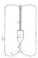
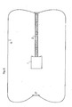
- - les figures 2, 3, 4, 5, 6, 7 sont des vues en coupe schématiques illustrant le déroulement du procédé de développement d'une enveloppe étanche autour d'un objet, conformément à l'invention.
- FIGS. 1a, 1b and 1c schematically illustrate the method of folding the envelopes used for implementing the method according to the invention,
- - Figures 2, 3, 4, 5, 6, 7 are schematic sectional views illustrating the progress of the development process of a sealed envelope around an object, according to the invention.
Ce procédé nécessite, en premier lieu, un ballon 2, dit ballon de liaison, qui est réalisé en assemblant des fuseaux rectangulaires, par tout procédé connu, tel que par exemple décrit dans la demande de brevet français no 80.00343 au nom du demandeur, le long de leurs bords rectilignes. Ce ballon comporte ainsi une portion cylindrique qui se prolonge par des portions extrêmes froncées dont les bords sont rattachés à des pièces polaires 3 et 4 disposées aux pôles du ballon sur l'axe de celui-ci.This process requires, first, a
Le matériau constitutif est un matériau composite étanche à l'air, possédant, par exemple, une trame en polyester disposée dans le sens circonférentiel et une chaîne en "Kevlar" disposée dans le sens longitudinal. Il possède ainsi une résistance dissymétrique plus élevée dans le sens longitudinal que dans le sens circonférentiel.The constituent material is an airtight composite material, having, for example, a polyester weft arranged in the circumferential direction and a "Kevlar" warp arranged in the longitudinal direction. It therefore has a higher asymmetric resistance in the longitudinal direction only in the circumferential direction.
Ce ballon est entouré d'un réseau de renforts circonférentiels 5 et d'un réseau de renforts longitudinaux 6. Chacun des ces renforts est réalisé en un matériau inextensible de haute résistance, par exemple "Kevlar".This balloon is surrounded by a network of circumferential reinforcements 5 and a network of
Par ailleurs, les pièces polaires 3 et 4 sont réunies par un lien interpolaire 7 inextensible s'étendant le long de l'axe du ballon ; ce lien 7 peut également être constitué d'un faisceau de bandes en un matériau inextensible de haute résistance, notamment "Kevlar".Furthermore, the
La structure de ce ballon 2, conforme au ballon décrit dans la demande de brevet français no 84.18798 au nom du demandeur, permet de le gonfler à des surpressions élevées, les efforts de tension étant repris par le lien interpolaire 7, le réseau longitudinal 6 et le réseau circonférentiel 5.The structure of the
En deuxième lieu, le procédé nécessite, pour sa mise en oeuvre, une enveloppe 8, dite enveloppe interne de volume et de longueur supérieurs au volume du ballon de liaison 2. Cette enveloppe première 8 est fabriquée de manière analogue au ballon de liaison par assemblage de fuseaux rectangulaires. Ces fuseaux sont réunis et fixés, au niveau d'une de leur extrémité, sur une des pièces polaires 3 du ballon de liaison 2 et au niveau de leur extrémité opposée sur une autre pièce polaire 9.Secondly, the method requires, for its implementation, an
Cette enveloppe première 8 possède la même structure que le ballon de liaison 2 si l'on excepte le lien interpolaire 7 qui est supprimé.This
En dernier lieu, le procédé nécessite une deuxième enveloppe 10, dite enveloppe externe, de volume supérieur à l'enveloppe première 8. Cette enveloppe 10 est également fabriquée de manière analogue au ballon de liaison 2 par assemblage de fuseaux rectangulaires.Finally, the method requires a
Cette enveloppe externe 10 est enfilée partiellement autour de l'enveloppe interne 8 ; une des extrémités des fuseaux la composant est alors fixée sur la pièce polaire 3 commune au ballon de liaison 2 et à l'enveloppe interne 8.This
Cette envelope externe 10 est ensuite plissée longitudinalement jusqu'à ce que l'extrémité opposée des fuseaux se trouve à distance des pôles 3, 9 de l'enveloppe interne 8 en regard d'une zone de renfort 11 circonférentielle de cette enveloppe interne. L'extrémité des fuseaux est alors fixée sur cette zone renforcée 11 par tout moyen connu tel que couture ou thermocellage ; l'assemblage est finalement renforcé au moyen de renforts circonférentiels 12, tels que des câbles en kevlar, qui assurent un frettage de cet assemblage.This
Les enveloppes interne 8 et externe 10 étant ainsi associées (figure 1a), l 'enveloppe interne 8 est alors retroussée sur elle-même (figure 1b), puis ces deux enveloppes sont pliées longitudinalement en accordéon en respectant la position retroussée de l'enveloppe interne (figure 1c). Le ballon de liaison 2 est quant à lui plié longitudinalement de façon classique.The inner 8 and outer 10 envelopes being thus associated (FIG. 1a), the
L'ensemble constitué par le ballon de liaison 2 et les enveloppes interne 8 et externe 10 est ensuite intégré à l'intérieur d'un container 13 ; les pôles 4, 9 respectifs du ballon de liaison 2 et de l'enveloppe interne 8 sont quant à eux solidairisés à une des parois de ce container 13.The assembly constituted by the
Il convient de noter que par container, on entend définir tout compartiment adapté pour loger le ballon de liaison et les deux enveloppes. Il est bien entendu que ce compartiment peut être constitué d'un élément séparé destiné à être fixé sur l'objet ou d'un élément, tel qu'une soute, ménagé directement à l'intérieur de cet objet.It should be noted that by container is meant to define any compartment suitable for housing the connection balloon and the two envelopes. It is understood that this compartment may consist of a separate element intended to be fixed on the object or of an element, such as a hold, formed directly inside this object.
A l'intérieur de ce container 13 sont également intégrés des moyens de gonflage, non représentés, du ballon de liaison 2 et des deux enveloppes 8, 10.Inside this
Ces moyens de gonflage sont dotés de moyens d'alimentation communiquant avec l'intérieur du ballon de liaison 2 et qui permettent une admission d'air comprimé provenant d'un turbo-compresseur (ou tout autre moyen équivalent) à travers un conduit.These inflation means are provided with supply means communicating with the interior of the
Associés à ces moyens de gonflage, des moyens de contrôle permettent de mesurer la pression relative à l'intérieur du ballon de liaison 2. Ces moyens de contrôle sont adaptés pour engendrer, pour une pression de consigne donnée, le déclenchement d'un séquenceur qui commande l'obturation du conduit alimentant le ballon de liaison 2 et l'ouverture d'un conduit dérivé communiquant avec l'intérieur de l'enveloppe interne 8.Associated with these inflation means, control means make it possible to measure the relative pressure inside the
Les différentes caractéristiques du ballon 2, des deux enveloppes 8, 10 et des moyens de gonflage ayant été décrites, on va indiquer ci-après le déroulement des opérations de développement de ces enveloppes autour d'un objet 1, en référence aux figures 2 à 7.The different characteristics of the
Le ballon de liaison 2 et les deux enveloppes 8, 10 sont logés à l'état dégonflé à l'intérieur du container 13 destiné à être solidarisé sur une face de l'objet 1. Un des pôles 4, 9 du ballon de liaison 2 et respectivement de l'enveloppe interne 8 est, comme cité ci-avant, solidarisé à une des parois du container 13.The
Il convient de noter que ce container 13 qui contient également les moyens de gonflage, est de dimensions et d'un poids relativement faibles, étant donné le peu d'encombrement des différentes enveloppes à leur état dégonflé.It should be noted that this
Les moyens de gonflage permettent, dans un premier temps, le gonflage du mât de liaison 2 jusqu'à l'obtention de son état de plénitude où il se trouve développé dans le prolongement de l'objet 1. Dans cet état de plénitude, ce ballon de liaison 2 permet de maintenir le pôle commun 3 des enveloppes interne 8 et externe 10 à distance de l'objet 1 (figure 2).The inflation means allow, initially, the inflation of the connecting
Au-delà d'une pression supérieure à une pression de consigne donnée, le séquenceur associé aux moyens de gonflage coupe l'alimentation en air de ce ballon 2 et active le remplissage de l'enveloppe interne 8.Beyond a pressure higher than a given set pressure, the sequencer associated with the inflation means cuts the air supply to this
Au cours de ce remplissage, la partie de l'enveloppe interne 8 se trouvant dans le prolongement de l'objet 1 se gonfle dans un premier temps, jusqu'à son état de plénitude. Dans un deuxième temps, de par sa position retroussée et la présence du ballon de liaison 2, cette enveloppe interne 8 se développe le long de l'objet 1 et finalement dans le prolongement de la face de cet objet opposée au ballon de liaison 2.During this filling, the part of the
Il est à noter que la section de cette enveloppe interne 8 doit être de taille supérieure à celle de l'objet, de façon à permettre son coulissement le long de cet objet 1.It should be noted that the section of this
Dans son état de plénitude, l'enveloppe interne 8 se trouve donc développée autour de l'objet 1 (figure 3).In its fullness state, the
Le gonflage est alors poursuivi jusqu'à obtenir le déchirement des lobes apparaissant entres les renforts circonférentiels 15 de cette enveloppe ; l'enveloppe externe 10 est alors gonflée rapidement au moyen de l'air circulant dans les ouvertures 16 libérées par le déchirement des lobes, et ce jusqu'à l'obtention de son état de plénitude (figure 4).The inflation is then continued until tearing of the lobes appearing between the
La reprise des efforts de tension s'exerçant sur cette structure développée est alors assurée par le ballon de liaison 2 qui donne à cet ensemble une bonne rigidité en traction et en flexion. Il convient de noter que ce ballon de liaison 2 peut être remplacé par un mât de liaison rigide, rétractable.The resumption of the tension forces exerted on this developed structure is then ensured by the connecting
La destruction de l'enveloppe interne 8 peut ensuite être poursuivie jusqu'à faire disparaître entièrement la partie extérieure de cette enveloppe. Seule subsiste alors la partie 8a reliant l'objet 1 au pôle de l'enveloppe externe 10, opposé au ballon de liaison 2 (figure 5).The destruction of the
Par la suite, afin de libérer le volume occupé par cette dernière partie 8a d'enveloppe interne 8, le pôle précité de l'enveloppe externe 10 est muni d'une pièce polaire 17 hermétique destinée à assurer l'étanchéité de la structure, puis l'enveloppe interne 8 est totalement détruite (figure 6).Subsequently, in order to release the volume occupied by this
On obtient finalement une libération de la totalité du volume autour de l'objet, en gonflant le mât de liaison 2 jusqu'à rupture des lobes apparaissant entre les renforts circonférentiels 5. La reprise des efforts de tension et la rigidité de la structure sont alors assurés par le lien interpolaire 7 de ce ballon de liaison 2 (figure 7).We finally obtain a release of the entire volume around the object, by inflating the connecting
La structure finale obtenue est donc une structure radiale développée autour de l'objet. En outre, ce volume est accessible depuis toutes les faces de l'objet.The final structure obtained is therefore a radial structure developed around the object. In addition, this volume is accessible from all sides of the object.
L'enveloppe externe 10 de cette structure peut également être rigidifiée en utilisant une enveloppe double paroi et en injectant une mousse rigidifiante dans l'intervalle compris entre ces deux parois.The
Cette dernière possibilité permet de créer un volume à l'intérieur duquel ne règne aucune surpression à condition de positionner deux mâts rigides reliant chaque pôle de l'enveloppe externe à une face de l'objet.This last possibility creates a volume inside which there is no overpressure provided that two rigid masts are connected connecting each pole of the external envelope to one face of the object.
Claims (18)
- à envelopper l'objet (1) d'une enveloppe étanche (8) se présentant à l'état dégonflé,
- à relier une zone (9) de cette enveloppe, dite pôle, avec l'objet par l'intermédiaire d'un mât de liaison (2) susceptible de pouvoir présenter deux positions extrêmes :
. une position repliée où il maintient le pôle (9) de l'enveloppe (8) sensiblement contre l'objet (1),
. une position déployée où il maintient le pôle (9) de l'enveloppe (8), à distance, en regard de l'objet (1),
. ledit mât de liaison (2) se trouvant initialement dans sa position repliée,
. à engendrer le déploiement du mât (2) entre sa position repliée et sa position déployée,
. à gonfler l'enveloppe (8) jusqu'à l'obtention de son état de plénitude.
- wrapping the object (1) in a sealed envelope (8) which is in the deflated state,
- to connect a zone (9) of this envelope, called a pole, with the object by means of a connecting mast (2) capable of having two extreme positions:
. a folded position where it maintains the pole (9) of the envelope (8) substantially against the object (1),
. a deployed position where it maintains the pole (9) of the envelope (8), at a distance, facing the object (1),
. said connecting mast (2) being initially in its folded position,
. to generate the deployment of the mast (2) between its folded position and its deployed position,
. inflating the envelope (8) until its state of fullness is obtained.
- à utiliser une enveloppe (8), dite interne, de forme allongée ayant deux pôles (3, 9) opposés à chacune de ses extrémités, à retrousser ladite enveloppe sur elle-même, et à la plier longitudinalement, en accordéon, dans cette position retroussée,
- à solidariser le pôle (9) de l'enveloppe interne se trouvant dans la partie retroussée sur l'objet (1) et à relier l'autre pôle (3) de l'enveloppe (8) audit objet par l'intermédiaire d'un mât de liaison (2), de longueur inférieure à ladite enveloppe, se trouvant dans sa position repliée.2 / - Method according to claim 1, characterized in that, in the prior phase, it consists:
- to use an envelope (8), said internal, of elongated shape having two poles (3, 9) opposite at each of its ends, to roll up said envelope on itself, and to fold it longitudinally, in accordion, in this rolled up position,
- to secure the pole (9) of the internal envelope located in the upturned part on the object (1) and to connect the other pole (3) of the envelope (8) to said object via 'a connecting mast (2), of length less than said envelope, being in its folded position.
- à utiliser une deuxème enveloppe (10), dite externe, de volume supérieur à l'enveloppe interne et possédant deux pôles à chacune de ses extrémités, un desdits pôles étant ouvert et de forme annulaire,
- à enfiler partiellement, en la plissant, l'enveloppe externe (10) autour de l'enveloppe (8) interne, avant pliage de celle-ci, de façon que le pôle annulaire de ladite enveloppe externe (10) soit fixé sur la périphérie de l'enveloppe interne (8) à distance de ses pôles (3, 9), l'autre pôle de l'enveloppe externe étant commun au pôle (3) de l'enveloppe interne (8) destiné à être fixé sur le mât de liaison (2),
- à retrousser, puis à plier ensemble longitudinalement, en accordéon, les deux enveloppes (8, 10) ainsi associées,
- à solidariser un des pôles (9) de l'enveloppe interne sur l'objet et à relier le pôle (3) commun des enveloppes interne (8) et externe (10) audit objet par l'intermédiaire du mât de liaison (2) se trouvant dans sa position repliée,
. à engendrer le déploiement du mât de liaison (2),
. à gonfler l'enveloppe interne (8) jusqu'à son état de plénitude où elle se trouve développée autour de l'objet (1),
. à poursuivre le gonflage jusqu'à rupture de la paroi périphérique extérieure de l'enveloppe interne (8),
. à gonfler l'enveloppe externe (10) jusqu'à son état de plénitude.
to use a second envelope (10), said to be external, of volume greater than the internal envelope and having two poles at each of its ends, one of said poles being open and of annular shape,
- to partially thread, by pleating, the external envelope (10) around the internal envelope (8), before folding thereof, so that the annular pole of said external envelope (10) is fixed on the periphery of the internal envelope (8) at a distance from its poles (3, 9), the other pole of the external envelope being common to the pole (3) of the internal envelope (8) intended to be fixed on the link mast (2),
- to roll up, then to fold together longitudinally, in accordion, the two envelopes (8, 10) thus associated,
- to secure one of the poles (9) of the internal envelope to the object and to connect the pole (3) common of the internal (8) and external (10) envelopes to said object by means of the connecting mast (2 ) being in its folded position,
. to generate the deployment of the link mast (2),
. inflating the internal envelope (8) to its fullness state where it is developed around the object (1),
. continuing to inflate until the outer peripheral wall of the internal envelope (8) ruptures,
. inflating the outer envelope (10) to its fullness state.
- on utilise une enveloppe interne (8) dotée d'une zone (11) renforcée circonférentielle, à distance de ses pôles (3, 9),
- on assemble le pôle annulaire de l'enveloppe externe (10) sur ladite zone renforcée de l'enveloppe interne (8),
- et on réalise un frettage dudit assemblage par des renforts circonférentiels (12).6 / - Method according to one of claims 4 or 5, characterized in that:
an internal envelope (8) is used which has a reinforced circumferential zone (11), at a distance from its poles (3, 9),
the annular pole of the external envelope (10) is assembled on said reinforced zone of the internal envelope (8),
- And a hooping of said assembly is carried out by circumferential reinforcements (12).
- un mât de liaison (2) possédant une extrémité (4) solidaire du container et adapté pour pouvoir présenter deux positions extrêmes :
. une position repliée où il est replié à l'intérieur du container (13),
. une position déployée où il s'étend à l'extérieur du container (13),
- une première enveloppe (8) cylindrique, dite interne, possédant un pôle (9) solidaire du container (13) et un pôle (3) solidaire de l'extrémité du mât de liaison (2), ladite enveloppe interne étant pliée en accordéon dans le container, dans une position retroussée,
- une deuxième enveloppe (10), dite enveloppe externe enfilée partiellement autour de l'enveloppe interne (8) avant pliage de celle-ci et possédant un pôle annulaire ouvert solidaire de la paroi périphérique de ladite enveloppe interne et un pôle (3) solidaire de l'extrémité du mât de liaison (2),
- des moyens de gonflage adaptés pour permettre le gonflage successif de l'enveloppe interne (8) et de l'enveloppe externe (10).14 / - Device intended to be secured to an object (1) for implementing the method according to one of the preceding claims and characterized in that it comprises a container (13) intended to be secured to said object ( 1) and containing:
- a connecting mast (2) having one end (4) integral with the container and adapted to be able to have two extreme positions:
. a folded position where it is folded back inside the container (13),
. a deployed position where it extends outside the container (13),
- A first cylindrical envelope (8), called internal, having a pole (9) integral with the container (13) and a pole (3) integral with the end of the connecting mast (2), said internal envelope being folded in accordion in the container, in a rolled up position,
- A second envelope (10), said external envelope partially threaded around the internal envelope (8) before folding thereof and having an open annular pole integral with the peripheral wall of said internal envelope and a pole (3) integral from the end of the connecting mast (2),
- Inflation means adapted to allow the successive inflation of the internal envelope (8) and the external envelope (10).
- des moyens d'alimentation permettant le gonflage successif du ballon de liaison (2) et des enveloppes interne (8) et externe (10),
- des moyens de contrôle de la pression relative du ballon de liaison (2) adaptés pour stopper le gonflage dudit ballon et commander le gonflage de l'enveloppe interne (8) pour une pression relative du ballon de liaison (2) supérieure à une valeur de consigne donnée.16 / - Device according to claim 15, characterized in that the inflation means comprise:
supply means allowing the successive inflation of the connecting balloon (2) and the internal (8) and external (10) envelopes,
- means for controlling the relative pressure of the connection balloon (2) adapted to stop the inflation of said balloon and control the inflation of the internal envelope (8) for a relative pressure of the connection balloon (2) greater than a value given instruction.
Applications Claiming Priority (2)
| Application Number | Priority Date | Filing Date | Title |
|---|---|---|---|
| FR8605097A FR2596727B1 (en) | 1986-04-08 | 1986-04-08 | METHOD AND DEVICE FOR DEVELOPING AN ENVELOPE AROUND AN OBJECT IN PARTICULAR A SATELLITE |
| FR8605097 | 1986-04-08 |
Publications (2)
| Publication Number | Publication Date |
|---|---|
| EP0241970A1 true EP0241970A1 (en) | 1987-10-21 |
| EP0241970B1 EP0241970B1 (en) | 1989-07-05 |
Family
ID=9334080
Family Applications (1)
| Application Number | Title | Priority Date | Filing Date |
|---|---|---|---|
| EP87200559A Expired EP0241970B1 (en) | 1986-04-08 | 1987-03-24 | Method and device to develop a casing round an article, especially a satellite |
Country Status (6)
| Country | Link |
|---|---|
| US (1) | US4770374A (en) |
| EP (1) | EP0241970B1 (en) |
| DE (1) | DE3760294D1 (en) |
| ES (1) | ES2009833B3 (en) |
| FR (1) | FR2596727B1 (en) |
| GR (1) | GR3000127T3 (en) |
Cited By (1)
| Publication number | Priority date | Publication date | Assignee | Title |
|---|---|---|---|---|
| US5156361A (en) * | 1988-08-16 | 1992-10-20 | Lang Mark S | Modular space station |
Families Citing this family (8)
| Publication number | Priority date | Publication date | Assignee | Title |
|---|---|---|---|---|
| US6213430B1 (en) * | 1999-01-05 | 2001-04-10 | Trw Inc. | Vehicle launch system having an acoustic insulator |
| US6786456B2 (en) * | 2002-08-29 | 2004-09-07 | L'garde, Inc. | Deployable inflatable boom and methods for packaging and deploying a deployable inflatable boom |
| US7204460B2 (en) * | 2004-06-24 | 2007-04-17 | Bigelow Aerospace | Orbital debris shield |
| US7780118B2 (en) * | 2004-07-29 | 2010-08-24 | Bigelow Aerospace | Radiation shield |
| US7401752B2 (en) | 2004-09-14 | 2008-07-22 | The Boeing Company | Protective shield assembly for space optics and associated methods |
| FR2903626B1 (en) * | 2006-07-12 | 2008-10-10 | Eads Space Transp Sas Soc Par | ASSEMBLY OF PREIMPREGNES FOR THE PRODUCTION OF STRUCTURES, FOR EXAMPLE A DEPLOYMENT BY INFLATION |
| US8070105B2 (en) * | 2007-12-14 | 2011-12-06 | The United States Of America As Represented By The Administrator Of The National Aeronautics And Space Administration | Inflatable nested toroid structure |
| CN106516164A (en) * | 2016-12-24 | 2017-03-22 | 哈尔滨工业大学 | Orderly unfolding flexible air inflation supporting arm |
Citations (4)
| Publication number | Priority date | Publication date | Assignee | Title |
|---|---|---|---|---|
| US4166598A (en) * | 1974-05-30 | 1979-09-04 | The United States Of America As Represented By The Secretary Of The Air Force | Vehicle enshrouding apparatus |
| US4166597A (en) * | 1974-05-09 | 1979-09-04 | The United States Of America As Represented By The Secretary Of The Air Force | Stowable and inflatable vehicle |
| US4314682A (en) * | 1969-02-24 | 1982-02-09 | Rockwell International Corporation | Deployable shield |
| US4504031A (en) * | 1979-11-01 | 1985-03-12 | The Boeing Company | Aerodynamic braking and recovery method for a space vehicle |
Family Cites Families (1)
| Publication number | Priority date | Publication date | Assignee | Title |
|---|---|---|---|---|
| FR1485587A (en) * | 1966-03-22 | 1967-06-23 | Device for improving landing on a satellite and in particular on the moon |
-
1986
- 1986-04-08 FR FR8605097A patent/FR2596727B1/en not_active Expired
-
1987
- 1987-03-24 DE DE8787200559T patent/DE3760294D1/en not_active Expired
- 1987-03-24 EP EP87200559A patent/EP0241970B1/en not_active Expired
- 1987-03-24 ES ES87200559T patent/ES2009833B3/en not_active Expired
- 1987-04-07 US US07/035,576 patent/US4770374A/en not_active Expired - Fee Related
-
1989
- 1989-08-21 GR GR89400145T patent/GR3000127T3/en unknown
Patent Citations (4)
| Publication number | Priority date | Publication date | Assignee | Title |
|---|---|---|---|---|
| US4314682A (en) * | 1969-02-24 | 1982-02-09 | Rockwell International Corporation | Deployable shield |
| US4166597A (en) * | 1974-05-09 | 1979-09-04 | The United States Of America As Represented By The Secretary Of The Air Force | Stowable and inflatable vehicle |
| US4166598A (en) * | 1974-05-30 | 1979-09-04 | The United States Of America As Represented By The Secretary Of The Air Force | Vehicle enshrouding apparatus |
| US4504031A (en) * | 1979-11-01 | 1985-03-12 | The Boeing Company | Aerodynamic braking and recovery method for a space vehicle |
Cited By (1)
| Publication number | Priority date | Publication date | Assignee | Title |
|---|---|---|---|---|
| US5156361A (en) * | 1988-08-16 | 1992-10-20 | Lang Mark S | Modular space station |
Also Published As
| Publication number | Publication date |
|---|---|
| ES2009833B3 (en) | 1989-10-16 |
| US4770374A (en) | 1988-09-13 |
| FR2596727B1 (en) | 1988-06-10 |
| FR2596727A1 (en) | 1987-10-09 |
| EP0241970B1 (en) | 1989-07-05 |
| DE3760294D1 (en) | 1989-08-10 |
| GR3000127T3 (en) | 1990-11-29 |
Similar Documents
| Publication | Publication Date | Title |
|---|---|---|
| EP1966064B1 (en) | Improved valve bag | |
| EP0241970B1 (en) | Method and device to develop a casing round an article, especially a satellite | |
| FR2574369A1 (en) | PILOTABLE AEROSTATIC BALLOON | |
| EP1873061B1 (en) | Retractable structure comprising rigid elements on board a spacecraft | |
| EP1960265B1 (en) | Airliftable tank for storing a product that is to be jettisoned during flight | |
| FR2990770B1 (en) | METHOD AND SYSTEM FOR RECOVERING MARINE GEOPHYSIC SEARCH SENSOR MARINE FLUTES | |
| EP2440446A1 (en) | Inflatable evacuation ramp and ship rescue equipment including same | |
| EP0031981A2 (en) | Process for producing an outer covering, especially for space balloons, produced outer covering, and its use in the field of aerospace | |
| EP1805081B1 (en) | Device for controlling the deployment of inflatable structures | |
| WO2010037791A1 (en) | Device for picking up objects floating on the water, such as hydrocarbons | |
| EP1468910B1 (en) | Foldable and deployable assembly of elements in a spacecraft | |
| FR2578508A1 (en) | INFLATABLE LIFTING BRACKET | |
| CA2370052C (en) | Floating inflatable pneumatic device, in particular an inflatable survival raft, equipped with a venturi-based inflation mechanism | |
| EP1203526A1 (en) | Bad weather protecting device, particularly for plants | |
| EP0033020B1 (en) | Process and device for launching and inflating a space balloon | |
| FR2683305A1 (en) | IMPROVEMENT IN SYSTEMS COMPRISING AN EXTENDABLE DEPLOYABLE ELEMENT WITH PYROTECHNIC FUNCTION. | |
| EP0091841B1 (en) | Device to be deployed for the extension of the exhaust nozzle of a rocket engine | |
| EP0401891A1 (en) | Balloon adapted to perform a self-governing and reversible flight between the ground of a planet with an atmosphere and a predetermined altitude | |
| FR2780819A1 (en) | Elastically deformable antenna reflector for spacecraft | |
| FR2734856A1 (en) | DEPLOYABLE AND RETRACTABLE INFLATABLE VOUTE | |
| CA2323714C (en) | Device for rolling out on the floor a rolled stored temporary surface covering | |
| FR2521281A1 (en) | WING HOUSING AND LID DISENGAGING DEVICE FOR AUTOMATIC ERECTION WING FOR SPECIAL EQUIPMENT | |
| FR2529961A1 (en) | Anti-theft pump | |
| FR2841533A1 (en) | Collision protector for transport vehicle comprises inflatable structure with controlled air outlet system deployed before impact | |
| FR2724350A1 (en) | Airbag with peripheral inflation for e.g. motor vehicle |
Legal Events
| Date | Code | Title | Description |
|---|---|---|---|
| PUAI | Public reference made under article 153(3) epc to a published international application that has entered the european phase |
Free format text: ORIGINAL CODE: 0009012 |
|
| AK | Designated contracting states |
Kind code of ref document: A1 Designated state(s): BE CH DE ES FR GB GR IT LI LU NL |
|
| 17P | Request for examination filed |
Effective date: 19871120 |
|
| 17Q | First examination report despatched |
Effective date: 19880817 |
|
| GRAA | (expected) grant |
Free format text: ORIGINAL CODE: 0009210 |
|
| AK | Designated contracting states |
Kind code of ref document: B1 Designated state(s): BE CH DE ES FR GB GR IT LI LU NL |
|
| REF | Corresponds to: |
Ref document number: 3760294 Country of ref document: DE Date of ref document: 19890810 |
|
| ITF | It: translation for a ep patent filed |
Owner name: ORGANIZZAZIONE D'AGOSTINI |
|
| GBT | Gb: translation of ep patent filed (gb section 77(6)(a)/1977) | ||
| PLBE | No opposition filed within time limit |
Free format text: ORIGINAL CODE: 0009261 |
|
| STAA | Information on the status of an ep patent application or granted ep patent |
Free format text: STATUS: NO OPPOSITION FILED WITHIN TIME LIMIT |
|
| REG | Reference to a national code |
Ref country code: GR Ref legal event code: FG4A Free format text: 3000127 |
|
| 26N | No opposition filed | ||
| ITTA | It: last paid annual fee | ||
| EPTA | Lu: last paid annual fee | ||
| PGFP | Annual fee paid to national office [announced via postgrant information from national office to epo] |
Ref country code: LU Payment date: 19960301 Year of fee payment: 10 |
|
| PGFP | Annual fee paid to national office [announced via postgrant information from national office to epo] |
Ref country code: GR Payment date: 19960305 Year of fee payment: 10 |
|
| PGFP | Annual fee paid to national office [announced via postgrant information from national office to epo] |
Ref country code: ES Payment date: 19960311 Year of fee payment: 10 |
|
| PGFP | Annual fee paid to national office [announced via postgrant information from national office to epo] |
Ref country code: BE Payment date: 19960313 Year of fee payment: 10 |
|
| PGFP | Annual fee paid to national office [announced via postgrant information from national office to epo] |
Ref country code: GB Payment date: 19960322 Year of fee payment: 10 |
|
| PGFP | Annual fee paid to national office [announced via postgrant information from national office to epo] |
Ref country code: FR Payment date: 19960326 Year of fee payment: 10 |
|
| PGFP | Annual fee paid to national office [announced via postgrant information from national office to epo] |
Ref country code: NL Payment date: 19960328 Year of fee payment: 10 |
|
| PGFP | Annual fee paid to national office [announced via postgrant information from national office to epo] |
Ref country code: CH Payment date: 19960409 Year of fee payment: 10 |
|
| PGFP | Annual fee paid to national office [announced via postgrant information from national office to epo] |
Ref country code: DE Payment date: 19960525 Year of fee payment: 10 |
|
| PG25 | Lapsed in a contracting state [announced via postgrant information from national office to epo] |
Ref country code: LU Free format text: LAPSE BECAUSE OF NON-PAYMENT OF DUE FEES Effective date: 19970324 Ref country code: GB Effective date: 19970324 |
|
| PG25 | Lapsed in a contracting state [announced via postgrant information from national office to epo] |
Ref country code: ES Free format text: LAPSE BECAUSE OF NON-PAYMENT OF DUE FEES Effective date: 19970325 |
|
| PG25 | Lapsed in a contracting state [announced via postgrant information from national office to epo] |
Ref country code: LI Effective date: 19970331 Ref country code: CH Effective date: 19970331 Ref country code: BE Effective date: 19970331 |
|
| BERE | Be: lapsed |
Owner name: CENTRE NATIONAL D'ETUDES SPATIALES CNES ETABLISSE Effective date: 19970331 |
|
| PG25 | Lapsed in a contracting state [announced via postgrant information from national office to epo] |
Ref country code: GR Free format text: THE PATENT HAS BEEN ANNULLED BY A DECISION OF A NATIONAL AUTHORITY Effective date: 19970930 |
|
| PG25 | Lapsed in a contracting state [announced via postgrant information from national office to epo] |
Ref country code: NL Effective date: 19971001 |
|
| REG | Reference to a national code |
Ref country code: GR Ref legal event code: MM2A Free format text: 3000127 |
|
| GBPC | Gb: european patent ceased through non-payment of renewal fee |
Effective date: 19970324 |
|
| REG | Reference to a national code |
Ref country code: CH Ref legal event code: PL |
|
| PG25 | Lapsed in a contracting state [announced via postgrant information from national office to epo] |
Ref country code: FR Free format text: LAPSE BECAUSE OF NON-PAYMENT OF DUE FEES Effective date: 19971128 |
|
| NLV4 | Nl: lapsed or anulled due to non-payment of the annual fee |
Effective date: 19971001 |
|
| PG25 | Lapsed in a contracting state [announced via postgrant information from national office to epo] |
Ref country code: DE Effective date: 19971202 |
|
| REG | Reference to a national code |
Ref country code: FR Ref legal event code: ST |
|
| REG | Reference to a national code |
Ref country code: ES Ref legal event code: FD2A Effective date: 19990201 |
|
| PG25 | Lapsed in a contracting state [announced via postgrant information from national office to epo] |
Ref country code: IT Free format text: LAPSE BECAUSE OF NON-PAYMENT OF DUE FEES;WARNING: LAPSES OF ITALIAN PATENTS WITH EFFECTIVE DATE BEFORE 2007 MAY HAVE OCCURRED AT ANY TIME BEFORE 2007. THE CORRECT EFFECTIVE DATE MAY BE DIFFERENT FROM THE ONE RECORDED. Effective date: 20050324 |