EP0241950A2 - Rotationsmaschine für Fluide - Google Patents
Rotationsmaschine für Fluide Download PDFInfo
- Publication number
- EP0241950A2 EP0241950A2 EP87108307A EP87108307A EP0241950A2 EP 0241950 A2 EP0241950 A2 EP 0241950A2 EP 87108307 A EP87108307 A EP 87108307A EP 87108307 A EP87108307 A EP 87108307A EP 0241950 A2 EP0241950 A2 EP 0241950A2
- Authority
- EP
- European Patent Office
- Prior art keywords
- rotor
- blades
- stationary cylinder
- cylinder
- inflow
- Prior art date
- Legal status (The legal status is an assumption and is not a legal conclusion. Google has not performed a legal analysis and makes no representation as to the accuracy of the status listed.)
- Granted
Links
Images


Classifications
-
- F—MECHANICAL ENGINEERING; LIGHTING; HEATING; WEAPONS; BLASTING
- F01—MACHINES OR ENGINES IN GENERAL; ENGINE PLANTS IN GENERAL; STEAM ENGINES
- F01C—ROTARY-PISTON OR OSCILLATING-PISTON MACHINES OR ENGINES
- F01C3/00—Rotary-piston machines or engines with non-parallel axes of movement of co-operating members
- F01C3/02—Rotary-piston machines or engines with non-parallel axes of movement of co-operating members the axes being arranged at an angle of 90 degrees
- F01C3/025—Rotary-piston machines or engines with non-parallel axes of movement of co-operating members the axes being arranged at an angle of 90 degrees of intermeshing engagement type, i.e. with engagement of co-operating members similar to that of toothed gearing
-
- F—MECHANICAL ENGINEERING; LIGHTING; HEATING; WEAPONS; BLASTING
- F02—COMBUSTION ENGINES; HOT-GAS OR COMBUSTION-PRODUCT ENGINE PLANTS
- F02B—INTERNAL-COMBUSTION PISTON ENGINES; COMBUSTION ENGINES IN GENERAL
- F02B3/00—Engines characterised by air compression and subsequent fuel addition
- F02B3/06—Engines characterised by air compression and subsequent fuel addition with compression ignition
Definitions
- the invention is concerned with rotary mechanisms, such as air compressors and pumps, for operating on fluids, and with rotary mechanisms, such as internal combustion engines and air or hydraulic motors, that are operated by fluids.
- US-A-2 250 368 discloses a rotary fluid-handling mechanism, comprising a rotor cylindrically recessed internally from one end thereof and provided with power transfer means; a stationary cylinder closely and sealingly fitted within the rotor recess; means for rotatably mounting the rotor relative to the cylinder; means holding the rotor on the cylinder; at least one pair of oppositely disposed, helically oriented cavities in the rotor, opening at the interior cylindrical surface thereof in confronting relationship with the cylindrical surface of the stationary cylinder; at least one corresponding pair of blades independently rotatably mounted within and at diametrically opposite sides of the stationary cylinder on respective axes at right angles to the axis of rotation of the rotor, so portions thereof will enter and pass through the respective cavities during synchronized rotation of the blades and the rotor; means for synchronizing rotation of the blades and the rotor; means for providing inflow of fluid internally of the mechanism into the paths of advancing movement of the blades within
- the object of the present invention is effective synchronizing means and means for providing inflow of fluid.
- the synchronizing means comprise a single shaft extending axially in the stationary cylinder, means in the cylinder journalling the shaft, and gearing interconnecting the shaft with the rotatable mountings of the blades; and the means for providing inflow of fluid internally of the mechanism include diametrically opposite passages flanking the shaft and synchronizing means and extending from inflow ports at the one end of the stationary cylinder towards the opposite end of the cylinder.
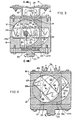
- an air compressor is mounted in cantilever fashion by a vertical supporting structure of any suitable construction. indicated at 15, to hold it securely during operation.
- mounting brackets 16 extend from securement in any suitable manner to a stationary, cylindrical blade support 17, see especially Figs. 2 and 9, which rotatably carries, in sealing relationship therewith, a rotor 18 internally recessed from one end thereof to receive the cylindrical blade support.
- the opposite end of rotor 18 is shown as being entirely closed by end plate 20a, but this is not a prerequisite.
- Sealing is conveniently effected by mixing oil vapors with intake air in customary manner. However, if rotor 18 is driven at high speed (about twenty thousand RPM), such sealing may not be necessary. In the event more effective sealing is required in certain instances, longitudinal sealing strips, indicated at S, Fig. 9, performing the function of well known piston rings, may be provided over and along opposite sides of each compressed air outlet port 19 and inlet port 29, which extends therethrough.
- Rotor 18 has a power input shaft 20 extending from fixed securement thereto at the end thereof opposite the aforesaid one end, as by means of removable closure plate 20a. Shaft 20 is coupled to motive means, such as an electric or other motor (not shown), in any suitable manner. Rotor 18 is provided internally with cavities, here shown as dual cavities 21, opening into its interior cylindrical surface 18a which is interfaced with the cylindrical surface of blade support 17.
- Blade support 17 is recessed internally to provide chambers 22 for respective blades 23, here a pair of same in keeping with the pair of cavities 21 provided by rotor 18.
- the chambers 22 are separated by a partition wall 27a, Figs. 2 and 8.
- Blades 23 and their respective chambers lie one above the other, and the blades are rotatably mounted on respective stub shafts 24 for rotation relative to each other.
- Rotation of the blades in synchronization and synchronized with rotation of the rotor is effected by geared interconnection with rotor 18, as by spur gear 25, Figs. 1. 2 and 3, rigidly held on rotor 18 and meshing with planetary gears 26 on respective countershafts 27 which have bevel gear interconections 28 with the respective blade stub shafts 24.
- Such synchronizing means is not in accordance with the present invention.
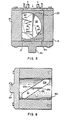
- Blades 23 are of any desired elongate configuration and rotate oppositely in their respective chambers 22. Their terminal ends pass into and through the respective cavities 21. which, being helically oriented with respect to the axis of rotation of the rotor, means that the volumetric capacities of the cavity portions in advance of the moving blades are progressively reduced and the air within such cavity portions is progressively compressed.
- the longitudinal edges of the blades are on the bias, as at 23a, so as to match the helical orientation of the longitudinal walls of the respective cavities.
- the terminal portions of the blades that contact the walls of the cavities are oil sealed as previously explained for low speed operation and require no sealing for high speed operation.
- power input shaft 20 is rotated counterclockwise, thereby rotating rotor 18 counterclockwise and advancing blades 23 in the directions of the appended arrows, providing balanced air-compressing strokes in those directions and compression of air within the portions 21a, Figs. 6 and 7, of lessening volumetric capacity, of respective rotor cavities 21.
- Air inlet ports 29, Figs. 2 and 9, at the cylindrical face of blade support 17 have respective passages 30 leading thereto from a port 31 at the outside-facing end of such blade support, through which atmospheric air is drawn into the compressor mechanism.
- the compressed air is discharged through smaller ports 19 into corresponding smaller passages 32 and through outlet ports and piping 33, Fig. 1, into a pressure tank (not shown) for use.
- Air-inflow ports and passages may be located in the rotor as shown in Fig. 10, where for each cavity 21 an interior port 34 is served by a passage 35 leading from an outer port 36 that is open to the atmosphere.
- Such arrangement may be used if desired with the elongate-bladed embodiment illustrated, but is necessary for a multi-spoked, "single screw" type of arrangement previously referred to but not illustrated.
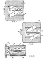
- a combustion chamber 37 is formed in the cylindrical blade support, here designated 38, and, except for diesel mode, a spark plug 39 is provided for igniting a fuel mixture compressed within such chamber.
- a fuel mixture is supplied from a suitable carburetor through an exterior intake port 40, Fig. 13, in the exposed end of cylindrical blade support 38, from where it flows through passage 41 leading to internal intake port 42.
- the spark plug is replaced by the usual fuel injector and the size of the combustion chamber is appropriately reduced.
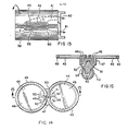
- Blades 43 are each preferably constructed as shown in Figs. 14 and 15 for purposes of convenient sealing as they traverse their respective cavities 44 in rotor 45.
- Each is made of two circular, bias-edged sections 46 arranged flatwise edge-to-edge and joined by an underlying, intermediate, circular section 47 which is securely fastened in place, as by press-fit pins 48, after installation of closely encircling sealing rings 49, that are similar to piston rings but are preferably of spring steel, by fastening opposite ends thereof to the respective sections 46, as by pivot pins 50.
- the opposite ends of such sealing rings are pivotally interconnected by a resilient strip 51, Fig. 14, usually of spring steel, pivoted centrally as indicated at 52.
- the blade as so made, is fixedly mounted on a stub shaft 53 provided with a bevel gear for intermeshing with the corresponding bevel gear of a gearing interconnection 54 with power offtake shaft 55 as previously described for the power input shaft 20 of the air compressor.
- Compression of the fuel mixture takes place at one side of the mechanism (the other side handles exhaust) as in the compressing strokes of the previously described air compressor.
- the compressed charge is transferred to the combustion chamber 37 near the end of the compression stroke through a port 56, Figs. 11 and 12, and passage 57, exhaust port 58 being closed by the internal surface of the rotor.
- combustion chamber intake port 56 is also closed by the internal surface of the rotor.
- exhaust port 58 is opened so that the burning gases expand into the rotor cavity 44 coming from the other side, the mechanism being driven thereby and a compression cycle commencing in such rotor cavity at the other face of the blade.
- Longitudinal sealing strips S, Fig. 12 and 13, are provided over and along ports 56 and 58, along ports 42 and 59, and along ports 19 and 29, Fig. 9, of the compressor.
- the mechanism is as illustrated in Figs. 1-9, except that the air-intake ports 29, Fig. 9, become the liquid intake ports and the discharge ports 19 must be elongated and relocated centrally to conform to ports 29 so the ports of both of these sets of ports will always be in communication with their corresponding rotor cavities during the respective cycles of operation.
- This does not mean that the discharge ports must be the same size as the intake ports, since volumetric discharge equal to volumetric intake can be achieved with unequal sizes by adjusting power input. This is desirable, since it provides the advantages of a positive displacement pump by a rotary mechanism.
- manifolds (similar to the piping 33, Fig. 1) should be provided interconnecting the intake ports and the discharge ports, respectively, so there will be a single intake and a single output for the pump.
- Hydraulic and air motors are constructed and function similarly to pumps.
- a turbo compressor of conventional type can be provided by adding turbo blades directly to and around the outer periphery of the rotor and sending the air so-pressurized to the carburetor or fuel injector in conventional manner.
- air can also be used to cool the rotor and the sealant oil as will be apparent to those skilled in the art.
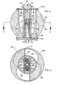
- FIGs. 16 and 17 show an air compressor in accordance with the present invention, which is a simplified version of the air compressor of Figs. 1-9.
- a cylindrical blade support 66 is firmly mounted as the stationary part of the device, as by means of a wall bracket 67, and rotatably carries a rotor 68, which is here shown as having a body 68a of generally spherical configuration to effectively accommodate dual cvities 69, respectively, opening into its interior cylindrical surface, which is interfaced with the cylindrical surface of blade support 66.
- a shaft 70 extends centrally of blade support 66, from rigid securement to rotor plate 68c, and is journaled by bearings 72 and 73. It fixedly carries a gear 74 that meshes with respective gears 75, Fig. 17, which are fixedly mounted on respective stub shafts 76 of respective blades 77.
- gears 75, Fig. 17, which are fixedly mounted on respective stub shafts 76 of respective blades 77.
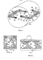
- Fig. 18 In instances in which the provision of sealing rings for the rotor is necessary, as when the mechanism is constructed as a motor, the system illustrated in Fig. 18 may be employee.
- longitudinal sealing strips 80 and 81 extending along one side of the rotor from end-to-end thereof and having respective set of arms 80a and 81a extending inwardly of such support from opposite ends therof, are hinged together at 82 and 83, respectively.
- Springs 84 between the arms at opposite ends, respectively, of the strips urge such strips toward each other so as to press them against the corresponding blade 77.
- Figs. 19 and 20 is also presently preferred and presented herein as a best mode presently contemplated for maximum volumetric handling of the fluids concerned.
- the blades 90 here, in cylindrical blade support 91 are of circular configuration with diametrically opposite, radial slots 92, respectively, into which fit helical walls 93, respectively, of rotor 94, which separate cavities 95 of such rotor.
- Drive mechanism for rotor 94 and air inlets and outlets are essentially the same as in the embodiment of Figs. 16 and 17.
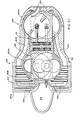
- Fig. 21 is an internal combustion engine similar to that of Fig. 11 shown here as an airplane engine for driving propellers 96, which are mounted in a nose portion 97a of rotor 97.
- Air is drawn in through the open front 99a of housing 99, which is adapted for attachment to the frame of an airplane, and is precompressed by compressor blades 97b affixed to rotor 97 and movable between stationary blades 99b affixed to housing 99.
- the precompressed air moves through passages 100 to a conventional fuel mixture system (not shown) in rear housing portion 99c. Exhaust gases are vented through opening 101 in housing portion 99c.
- a system for circulating and cooling lubricating oil may include the drive gearing 102, acting as a pump, and radiator coils 103.
- a sealing ring system similar to that of Fig. 18 may be employed in this internal combustion motor. It is illustrated in Fig. 25 and described hereinafter.
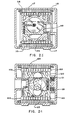
- Fig. 22 essentially the same internal combustion engine illustrated in Fig. 21 is shown coupled to an air compressor having circular blades similar to those of Fig. 19 and 20.
- the respective rotors 104a and 104b of engine 105 and compressor 106 are joined together as a single unit driven by the engine.
- Air is drawn into the engine through openings (not shown) in the front wall 107a of engine housing 107 and flows through precompressor 108 and passages 109 to compressor 106.
- Cylindrical blade supports 110 and 111 are rigidly fastened to housing 112, as by means of bolts (not shown), and the housing is secured to the frame of an airplane, where the device is used for jet propulsion, or to any suitable stationary mounting where used as an industrial air compressor.
- Engine exhaust may be directed through passages 113 for compression along with the air drawn in. Compressed air exits through respective passages 114.
- Fig. 23 is shown an air compressor corresponding in its essentials to that of Fig. 22, but incorporated in an electric motor of squirrel cage induction type, which serves as the drive means.
- Rotor 115 of the compressor unit carries a secondary, squirrel cage winding 116 and also serves as the rotor of the motor.
- Primary winding 117 is affixed to and carried by stationary housing 118 constituting the stator of the motor. Housing 118 also carries cylindrical blade holder 119. Electrical connections (not shown) for primary winding 117 to an alternating current power source are conventional.
- Fig. 28 is shown an internal combustion engine corresponding in its essentials to the air compression mechanism of Fig. 22, out incorporated in an electric generator of construction similar to that of the squirrel cage motor of Fig. 23.
- rotor 120 of the engine rotates, brushless, direct-current exciter 121 feeds current to rotor poles 122, thereby inducing voltage on stator windings 123.
- electrical connections are conventionaL This embodiment is especially useful as an electrical source unit for electric tractor wheels of vehicles and for ship propellors.
- Sealing is effected in the engines of the foregoing embodiments in a manner essentially similar to that shown in Fig. 18.
- a set of longitudinal sealing strips 124 and 125 at one side of the cylindrical blade support and having arms 124a and 125a, respectively, are hinged at 126 and 127, respectively.
- Springs 128 correspond to springs 84.
- a second set of longitudinal sealing strips 129 and 130, having arms 129a and 130, are similarly hinged at 131 and 132, respectively.
- Springs 133 correspond to springs 88.
- the sets of arms 124a and 125a and 129a and 130a, respectively, are urged apart by respective springs 134 acting on arm extensions 135 and 136, rather than by the respective sets of separate springs 85 and 89.
- Air for fuel mixture enters the corresponding compression chambers of the engine rotor through opening 137, compressed fuel mixture air enters the combustion chamber of the engine through opening 138, expansion gases from the combustion chamber enter the corresponding rotor cavity through opening 139, and exhaust gases pass out through opening 140.
- the invention is shown as the pump unit 142 of an artificial heart in construction similar to the unit shown in Figs. 16 and 17 and driven by both or by one or the other of respective, side-by-side mounted, direct current motors 143.
- Rotor 144 of pump unit 142 is of generally spherical formation, as is the rotor of Figs. 16 and 1Z, and is fitted within a conveniently heart-shaped housing 145, which is adapted to be suitably anchored in the body of a recipient human or animal.
- Cylindrical blade support 146 is affixed to housing 145 and rotatably carries circular blades 147, respectively, which are driven in synchronism with rotor 144 by geared interconnection as in Figs. 16 and 17.
- the design of blades 147 is such as to reproduce the natural pumping cycle of the heart which is replaced, e.g. the pumping cycle of the human heart wherein, in each cycle, a pause of one fourth of the cycle occurs.
- Electric cable 152 powers both motors by connection to an electrical battery carried externally of the body, and each of the motors drives rotor 144 by a respective pinion 153 meshing with a ring gear formation 154 of rotor 144.
- Each motor 143 is itself capable of driving rotor 144. The two are provided so that there is always a spare if one fails to operate effectively.
- Shaft 155 drives the synchronizing gears.
- the artificial heart is substantially actual size for pumping five liters of blood per minute at approximately thirty-five revolutions of the rotor per minute. If used as an assist for a natural heart, size and pumping capacity will be reduced accordingly.
- the parent application claims a rotary motor constructed as an internal combustion engine.
Landscapes
- Engineering & Computer Science (AREA)
- Mechanical Engineering (AREA)
- General Engineering & Computer Science (AREA)
- Structures Of Non-Positive Displacement Pumps (AREA)
- Details And Applications Of Rotary Liquid Pumps (AREA)
Priority Applications (1)
| Application Number | Priority Date | Filing Date | Title |
|---|---|---|---|
| AT87108307T ATE59429T1 (de) | 1984-07-06 | 1985-04-19 | Rotationsmaschine fuer fluide. |
Applications Claiming Priority (4)
| Application Number | Priority Date | Filing Date | Title |
|---|---|---|---|
| US62840684A | 1984-07-06 | 1984-07-06 | |
| US628406 | 1984-07-06 | ||
| US06/680,935 US4620515A (en) | 1984-07-06 | 1984-12-12 | Rotary fluid-handling mechanism constructed as an internal combustion engine |
| US680935 | 1984-12-12 |
Related Parent Applications (1)
| Application Number | Title | Priority Date | Filing Date |
|---|---|---|---|
| EP85302773.8 Division | 1985-04-19 |
Publications (3)
| Publication Number | Publication Date |
|---|---|
| EP0241950A2 true EP0241950A2 (de) | 1987-10-21 |
| EP0241950A3 EP0241950A3 (en) | 1988-04-20 |
| EP0241950B1 EP0241950B1 (de) | 1990-12-27 |
Family
ID=27090702
Family Applications (3)
| Application Number | Title | Priority Date | Filing Date |
|---|---|---|---|
| EP85302773A Expired EP0171135B1 (de) | 1984-07-06 | 1985-04-19 | Rotierende Anlage zur Fluidhandhabung |
| EP87108307A Expired EP0241950B1 (de) | 1984-07-06 | 1985-04-19 | Rotationsmaschine für Fluide |
| EP87108308A Expired EP0241951B1 (de) | 1984-07-06 | 1985-04-19 | Rotationsmaschine für Fluide |
Family Applications Before (1)
| Application Number | Title | Priority Date | Filing Date |
|---|---|---|---|
| EP85302773A Expired EP0171135B1 (de) | 1984-07-06 | 1985-04-19 | Rotierende Anlage zur Fluidhandhabung |
Family Applications After (1)
| Application Number | Title | Priority Date | Filing Date |
|---|---|---|---|
| EP87108308A Expired EP0241951B1 (de) | 1984-07-06 | 1985-04-19 | Rotationsmaschine für Fluide |
Country Status (4)
| Country | Link |
|---|---|
| US (1) | US4620515A (de) |
| EP (3) | EP0171135B1 (de) |
| DE (2) | DE3581213D1 (de) |
| MX (1) | MX166754B (de) |
Families Citing this family (14)
| Publication number | Priority date | Publication date | Assignee | Title |
|---|---|---|---|---|
| GB9908845D0 (en) * | 1999-04-19 | 1999-06-16 | Seneca Tech Ltd | Inverted engine configuration |
| DE102006044742A1 (de) | 2006-09-20 | 2008-04-03 | Schniewindt Gmbh & Co. Kg | Schiffsantrieb |
| CN110944689B (zh) | 2017-06-07 | 2022-12-09 | 施菲姆德控股有限责任公司 | 血管内流体运动设备、系统和使用方法 |
| EP3710076B1 (de) | 2017-11-13 | 2023-12-27 | Shifamed Holdings, LLC | Intravaskuläre fluidbewegungsvorrichtungen, systeme und verwendungsverfahren |
| EP4085965A1 (de) | 2018-02-01 | 2022-11-09 | Shifamed Holdings, LLC | Intravaskuläre blutpumpen und verfahren zur verwendung und herstellung |
| WO2020028537A1 (en) | 2018-07-31 | 2020-02-06 | Shifamed Holdings, Llc | Intravascaular blood pumps and methods of use |
| EP3860675A4 (de) | 2018-10-05 | 2022-07-13 | Shifamed Holdings, LLC | Intravaskuläre blutpumpen und verfahren zur verwendung |
| US11964145B2 (en) | 2019-07-12 | 2024-04-23 | Shifamed Holdings, Llc | Intravascular blood pumps and methods of manufacture and use |
| WO2021016372A1 (en) | 2019-07-22 | 2021-01-28 | Shifamed Holdings, Llc | Intravascular blood pumps with struts and methods of use and manufacture |
| EP4010046A4 (de) | 2019-08-07 | 2023-08-30 | Calomeni, Michael | Katheterblutpumpen und zusammenklappbare pumpengehäuse |
| WO2021062260A1 (en) | 2019-09-25 | 2021-04-01 | Shifamed Holdings, Llc | Catheter blood pumps and collapsible blood conduits |
| WO2021062265A1 (en) | 2019-09-25 | 2021-04-01 | Shifamed Holdings, Llc | Intravascular blood pump systems and methods of use and control thereof |
| US12102815B2 (en) | 2019-09-25 | 2024-10-01 | Shifamed Holdings, Llc | Catheter blood pumps and collapsible pump housings |
| EP4072650A4 (de) | 2019-12-11 | 2024-01-10 | Shifamed Holdings, LLC | Absteigende aorten- und hohlvenenblutpumpen |
Family Cites Families (11)
| Publication number | Priority date | Publication date | Assignee | Title |
|---|---|---|---|---|
| US2141982A (en) * | 1935-04-16 | 1938-12-27 | Paul E Good | Rotary motor |
| US2154328A (en) * | 1937-07-26 | 1939-04-11 | Paul E Good | Tube cleaner motor |
| GB509372A (en) * | 1937-07-27 | 1939-07-14 | Fritz Gfeller | Rotary piston engine |
| US2250368A (en) * | 1938-08-11 | 1941-07-22 | Paul E Good | Tube cleaner motor |
| US2243005A (en) * | 1938-11-22 | 1941-05-20 | Paul E Good | Tube cleaner motor |
| GB639344A (en) * | 1946-05-16 | 1950-06-28 | Jean Joosten | A rotary machine usable as an engine, a compressor, or a pump |
| US2500143A (en) * | 1946-09-26 | 1950-03-07 | Arnold E Biermann | Rotary abutment compressor |
| US3477414A (en) * | 1967-12-15 | 1969-11-11 | Marin A Alvaro | Rotary fluid-handling mechanism |
| US3739754A (en) * | 1970-12-03 | 1973-06-19 | A Nutku | Rotating-piston toroidal machine with rotating-disc abutment |
| FR2139751B1 (de) * | 1971-06-03 | 1975-02-21 | Rylewski Eugeniusz | |
| JPS6120314Y2 (de) * | 1979-03-13 | 1986-06-18 |
-
1984
- 1984-12-12 US US06/680,935 patent/US4620515A/en not_active Expired - Lifetime
-
1985
- 1985-04-19 DE DE8787108308T patent/DE3581213D1/de not_active Expired - Lifetime
- 1985-04-19 EP EP85302773A patent/EP0171135B1/de not_active Expired
- 1985-04-19 DE DE8787108307T patent/DE3581212D1/de not_active Expired - Lifetime
- 1985-04-19 EP EP87108307A patent/EP0241950B1/de not_active Expired
- 1985-04-19 EP EP87108308A patent/EP0241951B1/de not_active Expired
- 1985-07-05 MX MX205903A patent/MX166754B/es unknown
Also Published As
| Publication number | Publication date |
|---|---|
| EP0171135B1 (de) | 1989-10-25 |
| EP0241950A3 (en) | 1988-04-20 |
| EP0171135A1 (de) | 1986-02-12 |
| EP0241950B1 (de) | 1990-12-27 |
| DE3581212D1 (en) | 1991-02-07 |
| MX166754B (es) | 1993-02-01 |
| US4620515A (en) | 1986-11-04 |
| DE3581213D1 (en) | 1991-02-07 |
| EP0241951A3 (en) | 1988-04-20 |
| EP0241951B1 (de) | 1990-12-27 |
| EP0241951A2 (de) | 1987-10-21 |
Similar Documents
| Publication | Publication Date | Title |
|---|---|---|
| EP0241950B1 (de) | Rotationsmaschine für Fluide | |
| US4638776A (en) | Rotary internal combustion engine | |
| US4766729A (en) | Apparatus for transmitting power obtained by converting the exhaust energy of an engine | |
| KR930012225B1 (ko) | 회전식 이행정 내연기관 | |
| US3902465A (en) | Rotary engine | |
| US2845909A (en) | Rotary piston engine | |
| US3340853A (en) | Rotary piston engine | |
| US4024840A (en) | Engine and compressor arrangement | |
| US4634356A (en) | Rotary fluid-handling mechanism | |
| CA1261762A (en) | Rotary fluid-handling mechanism | |
| US4634355A (en) | Rotary fluid-handling mechanism | |
| US5125379A (en) | Rotary engine | |
| US3744941A (en) | Mechanism for rotary engine | |
| US4251992A (en) | Pneumatic propulsion system | |
| GB2169964A (en) | Rotary positive displacement device | |
| EP0288440B1 (de) | Umlaufverbrennungsmotor mit Axialkolben | |
| JPH081419U (ja) | 回転式内燃機関 | |
| US3552363A (en) | Rotary engine | |
| US1821139A (en) | Internal combustion engine | |
| US3176665A (en) | Rotary piston internal combustion engine | |
| JP2003120305A (ja) | 多シリンダーロータリーモータおよびその操作方法 | |
| JPS62129590A (ja) | 回転式流体処理機構 | |
| AU737023B2 (en) | Rotary piston pump and method of operation | |
| CN222950057U (zh) | 一种用于供油的滑片泵体 | |
| EP1085182B1 (de) | Rotierende Brennkraftmaschine |
Legal Events
| Date | Code | Title | Description |
|---|---|---|---|
| PUAI | Public reference made under article 153(3) epc to a published international application that has entered the european phase |
Free format text: ORIGINAL CODE: 0009012 |
|
| 17P | Request for examination filed |
Effective date: 19870702 |
|
| AC | Divisional application: reference to earlier application |
Ref document number: 171135 Country of ref document: EP |
|
| AK | Designated contracting states |
Kind code of ref document: A2 Designated state(s): AT BE CH DE FR GB IT LI LU NL SE |
|
| PUAL | Search report despatched |
Free format text: ORIGINAL CODE: 0009013 |
|
| AK | Designated contracting states |
Kind code of ref document: A3 Designated state(s): AT BE CH DE FR GB IT LI LU NL SE |
|
| 17Q | First examination report despatched |
Effective date: 19900228 |
|
| GRAA | (expected) grant |
Free format text: ORIGINAL CODE: 0009210 |
|
| AC | Divisional application: reference to earlier application |
Ref document number: 171135 Country of ref document: EP |
|
| AK | Designated contracting states |
Kind code of ref document: B1 Designated state(s): AT BE CH DE FR GB IT LI LU NL SE |
|
| PG25 | Lapsed in a contracting state [announced via postgrant information from national office to epo] |
Ref country code: SE Free format text: THE PATENT HAS BEEN ANNULLED BY A DECISION OF A NATIONAL AUTHORITY Effective date: 19901227 Ref country code: NL Effective date: 19901227 Ref country code: LI Effective date: 19901227 Ref country code: CH Effective date: 19901227 Ref country code: BE Effective date: 19901227 Ref country code: AT Effective date: 19901227 |
|
| REF | Corresponds to: |
Ref document number: 59429 Country of ref document: AT Date of ref document: 19910115 Kind code of ref document: T |
|
| REF | Corresponds to: |
Ref document number: 3581212 Country of ref document: DE Date of ref document: 19910207 |
|
| ET | Fr: translation filed | ||
| ITF | It: translation for a ep patent filed | ||
| REG | Reference to a national code |
Ref country code: CH Ref legal event code: PL |
|
| ITTA | It: last paid annual fee | ||
| PG25 | Lapsed in a contracting state [announced via postgrant information from national office to epo] |
Ref country code: LU Free format text: LAPSE BECAUSE OF NON-PAYMENT OF DUE FEES Effective date: 19910430 |
|
| NLV1 | Nl: lapsed or annulled due to failure to fulfill the requirements of art. 29p and 29m of the patents act | ||
| PLBE | No opposition filed within time limit |
Free format text: ORIGINAL CODE: 0009261 |
|
| STAA | Information on the status of an ep patent application or granted ep patent |
Free format text: STATUS: NO OPPOSITION FILED WITHIN TIME LIMIT |
|
| 26N | No opposition filed | ||
| PGFP | Annual fee paid to national office [announced via postgrant information from national office to epo] |
Ref country code: GB Payment date: 19940411 Year of fee payment: 10 Ref country code: FR Payment date: 19940411 Year of fee payment: 10 |
|
| PGFP | Annual fee paid to national office [announced via postgrant information from national office to epo] |
Ref country code: DE Payment date: 19940426 Year of fee payment: 10 |
|
| PG25 | Lapsed in a contracting state [announced via postgrant information from national office to epo] |
Ref country code: GB Effective date: 19950419 |
|
| GBPC | Gb: european patent ceased through non-payment of renewal fee |
Effective date: 19950419 |
|
| PG25 | Lapsed in a contracting state [announced via postgrant information from national office to epo] |
Ref country code: FR Effective date: 19951229 |
|
| PG25 | Lapsed in a contracting state [announced via postgrant information from national office to epo] |
Ref country code: DE Effective date: 19960103 |
|
| REG | Reference to a national code |
Ref country code: FR Ref legal event code: ST |