EP0241951A2 - Rotationsmaschine für Fluide - Google Patents
Rotationsmaschine für Fluide Download PDFInfo
- Publication number
- EP0241951A2 EP0241951A2 EP87108308A EP87108308A EP0241951A2 EP 0241951 A2 EP0241951 A2 EP 0241951A2 EP 87108308 A EP87108308 A EP 87108308A EP 87108308 A EP87108308 A EP 87108308A EP 0241951 A2 EP0241951 A2 EP 0241951A2
- Authority
- EP
- European Patent Office
- Prior art keywords
- rotor
- blades
- cavities
- fluid
- cylinder
- Prior art date
- Legal status (The legal status is an assumption and is not a legal conclusion. Google has not performed a legal analysis and makes no representation as to the accuracy of the status listed.)
- Granted
Links
Images


Classifications
-
- F—MECHANICAL ENGINEERING; LIGHTING; HEATING; WEAPONS; BLASTING
- F01—MACHINES OR ENGINES IN GENERAL; ENGINE PLANTS IN GENERAL; STEAM ENGINES
- F01C—ROTARY-PISTON OR OSCILLATING-PISTON MACHINES OR ENGINES
- F01C3/00—Rotary-piston machines or engines with non-parallel axes of movement of co-operating members
- F01C3/02—Rotary-piston machines or engines with non-parallel axes of movement of co-operating members the axes being arranged at an angle of 90 degrees
- F01C3/025—Rotary-piston machines or engines with non-parallel axes of movement of co-operating members the axes being arranged at an angle of 90 degrees of intermeshing engagement type, i.e. with engagement of co-operating members similar to that of toothed gearing
-
- F—MECHANICAL ENGINEERING; LIGHTING; HEATING; WEAPONS; BLASTING
- F02—COMBUSTION ENGINES; HOT-GAS OR COMBUSTION-PRODUCT ENGINE PLANTS
- F02B—INTERNAL-COMBUSTION PISTON ENGINES; COMBUSTION ENGINES IN GENERAL
- F02B3/00—Engines characterised by air compression and subsequent fuel addition
- F02B3/06—Engines characterised by air compression and subsequent fuel addition with compression ignition
Definitions
- the invention is concerned with rotary mechanisms, such as air compressors and pumps, for operating on fluids, and with rotary mechanisms, such as internal combustion engines and air or hydraulic motors, that are operated by fluids.
- the object of the present invention is an effective synchronizing means.
- the blades are elongate and the synchronizing means comprise sets of teeth projecting from opposite longitudinal edges, respectively, of the blades intermediate the lengths thereof, and there are corresponding sets of auxiliary cavities at opposite sides of the internal cylindrical surface of the rotor for receiving the respective teeth during operation of the mechanism.
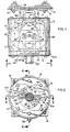
- an air compressor is mounted in cantilever fashion by a vertical supporting structure of any suitable construction, indicated at 15, to hold it securely during operation.
- mounting brackets 16 extend from securement in any suitable manner to a stationary, cylindrical blade support 17, see especially Figs. 2 and 9, which rotatably carries, in sealing relationship therewith, a rotor 18 internally recessed from one end thereof to receive the cylindrical blade support.
- the opposite end of rotor 18 is shown as being entirely closed by end plate 20a, but this is not a prerequisite.
- Sealing is conveniently effected by mixing oil vapors with intake air in customary manner. However, if rotor 18 is driven at high speed (about twenty thousand RPM), such sealing may not be necessary. In the event more effective sealing is required in certain instances, longitudinal sealing strips, indicated at S, Fig. 9, performing the function of well known piston rings, may be provided over and along opposite sides of each compressed air outlet port 19 and inlet port 29, which extends therethrough.
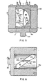
- Rotor 18 has a power input shaft 20 extending from fixed securement thereto at the end thereof opposite the aforesaid one end, as by means of removable closure plate 20a. Shaft 20 is coupled to motive means, such as an electric or other motor (not shown), in any suitable manner. Rotor 18 is provided internally with cavities, here shown as dual cavities 21, opening into its interior cylindrical surface 18a which is interfaced with the cylindrical surface of blade support 17.
- Blade support 17 is recessed internally to provide chambers 22 for respective blades 23, here a pair of same in keeping with the pair of cavities 21 provided by rotor 18.
- the chambers 22 are separated by a partition wall 17a, Figs. 2 and 8.
- Blades 23 and their respective chambers lie one above the other, and the blades are rotatably mounted on respective stub shafts 24 for rotation relative to each other.
- Rotation of the blades in synchronization and synchronized with rotation of the rotor is effected by geared interconnection with rotor 18, as by spur gear 25, Figs. 1. 2 and 3, rigidly held on rotor 18 and meshing with planetary gears 26 on respective countershafts 27 which have bevel gear interconnections 28 with the respective blade stub shafts 24.
- Such synchronizing means is not in accordance with the present invention.
- Blades 23 are of any desired elongate configuration and rotate oppositely in their respective chambers 22. Their terminal ends pass into and through the respective cavities 21, which, being helically oriented with respect to the axis of rotation of the rotor, means that the volumetric capacities of the cavity portions in advance of the moving blades are progressively reduced and the air within such cavity portions is progressively compressed.
- the longitudinal edges of the blades are on the bias, as at 23a. so as to match the helical orientation of the longitudinal walls of the respective cavities.
- the terminal portions of the blades that contact the walls of the cavities are oil sealed as previously explained for low speed operation and require no sealing for high speed operation.
- power input shaft 20 is rotated counterclockwise, thereby rotating rotor 18 counterclockwise and advancing blades 23 in the directions of the appended arrows, providing balanced air-compressing strokes in those directions and compression of air within the portions 21a, Figs. 6 and 7. of lessening volumetric capacity, of respective rotor cavities 21.
- Air inlet ports 29, Figs. 2 and 9, at the cylindrical face of blade support 17 have respective passages 30 leading thereto from a port 31 at the outside-facing end of such blade support, through which atmospheric air is drawn into the compressor mechanism.
- the compressed air is discharged through smaller ports 19 into corresponding smaller passages 32 and through outlet ports and piping 33, Fig. 1, into a pressure tank (not shown) for use.
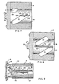
- a combustion chamber 37 is formed in the cylindrical blade support, here designated 38, and, except for diesel mode, a spark plug 39 is provided for igniting a fuel mixture compressed within such chamber.
- a fuel mixture is supplied from a suitable carburetor through an exterior intake port 40, Fig. 12, in the exposed end of cylindrical blade support 38, from where it flows through passage 41 leading to internal intake port 42.
- the spark plug is replaced by the usual fuel injector and the size of the combustion chamber is appropriately reduced.
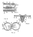
- Blades 43 are each preferably constructed as shown in Figs. 13 and 14 for purposes of convenient sealing as they traverse their respective cavities 44 in rotor 45.
- Each is made of two circular. bias-edged sections 46 arranged flatwise edge-to-edge and joined by an underlying. intermediate. circular section 47 which is securely fastened in place, as by press-fit pins 48, after installation of closely encircling sealing rings 49. that are similar to piston rings but are preferably of spring steel. by fastening opposite ends thereof to the respective sections 46, as by pivot pins 50.
- the opposite ends of such sealing rings are pivotally interconnected by a resilient strip 51, Fig. 13, usually of spring steel, pivoted centrally as indicated at 52.
- the blade as so made, is fixedly mounted on a stub shaft 53 provided with a bevel gear for intermeshing with the corresponding bevel gear of a gearing interconnection 54 with power offtake shaft 55 as previously described for the power input shaft 20 of the air compressor.
- Compression of the fuel mixture takes place at one side of the mechanism (the other side handles exhaust) as in the compressing strokes.of the previously described air compressor.
- the compressed charge is transferred to the combustion chamber 37 near the end of the compression stroke through a port 56.
- Figs. 10 and 11. and passage 57, exhaust port 58 being closed by the internal surface of the rotor.
- combustion chamber intake port 56 is also closed by the internal surface of the rotor.
- exhaust port 58 is opened so that the burning gases expand into the rotor cavity 44 coming from the other side. the mechanism being driven thereby and a compression cycle commencing in such rotor cavity at the other face of the blade.
- the mechanism is as illustrated in Figs. 1-9, except that the air-intake ports 29. Fig. 9, become the liquid intake ports and the discharge ports 19 must be elongated and relocated centrally to conform to ports 29 so the ports of both of these sets of ports will always be in communication with their corresponding rotor cavities during the respective cycles of operation.
- This does not mean that the discharge ports must be the same size as the intake ports, since volumetric discharge equal to volumetric intake can be achieved with unequal sizes by adjusting power input. This is desirable. since it provides the advantages of a positive displacement pump by a rotary mechanism.
- Manifolds (similar to the piping 33, Fig. 1) should be provided interconnecting the intake ports and the discharge ports, respectively, so there will be a single intake and a single output for the pump.
- Hydraulic and air motors are constructed and function similarly to pumps.
- a turbo compressor of conventional type can be provided by adding turbo blades directly to and around the outer periphery of the rotor and sending the air so-pressurized to the carburetor or fuel injector in conventional manner.
- air can also be used to cool the rotor and the sealant oil as will be apparent to those skilled in the art.
- Fig. 15 In instances in which the provision of sealing rings for the rotor is necessary, as when the mechanism is constructed as a motor, the system illustrated in Fig. 15 may be employed.
- longitudinal sealing strips 80 and 81 extending along one side of the rotor from end-to-end thereof and having respective set of arms 80a and 81a extending inwardly of such support from opposite ends thereof, are hinged together at 82 and 83, respectively.
- Springs 84 between the arms at opposite ends, respectively, of the strips urge such strips toward each other so as to press them against the corresponding blade 77.
- Springs 85 at the hinged ends, respectively, of the arms press sealing strips 80 and 81 against the cylindrical interior surface of the rotor as such rotor rotates.
- a set of similar sealing strips 86 and 87, respectively, at the opposite side of blade support 66 are similarly mounted and are similarly pressed by respective springs 88 and by respective springs 89 against the corresponding blade 77 and against the cylindrical interior surface of the rotor, respectively.
- the fluid to be compressed enters the compression chambers in the rotor through opening 78a, and compressed air discharges from such compression chambers through opening 79a.
- the combustion gases enter the expansion chambers in the rotor through opening 78b and the exhaust gases discharge through opening 79b.
- Fig. 16 shows the pump unit 142 of an artificial heart driven by both or by one or the other of respective, side-by-side mounted, direct current motors 143.
- Rotor 144 of pump unit 142 is of generally spherical formation and is fitted within a conveniently heart-shaped housing 145, which is adapted to be suitably anchored in the body of a recipient human or animal.
- Cylindrical blade support 146 is affixed to housing 145 and rotatably carries circular blades 147, respectively, which are driven in synchronism with rotor 144 by geared interconnection. Blood enters pump unit 142 through inlet passages 148 and 149, corresponding, respectively.
- blades 147 is such as to reproduce the natural pumping cycle of the heart which is replaced e.g. the pumping cycle of the human heart wherein, in each cycle, a pause of one fourth of the cycle occurs.
- Electric cable 152 powers both motors by connection to an electrical battery carried externally of the body, and each of the motors drives rotor 144 by a respective pinion 153 meshing with a ring gear formation 154 of rotor 144.
- Each motor 143 is itself capable of driving rotor 144. The two are provided so that there is always a spare if one fails to operate effectively.
- Shaft 155 drives the synchronizing gears.
- the artificial heart is substantially actual size for pumping five liters of blood per minute at approximately thirty-five revolutions of the rotor per minute. If used as an assist for a natural heart. size and pumping capacity will be reduced accordingly.
- the parent application claims a rotary motor constructed as an internal combustion engine.
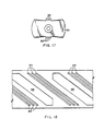
- the gearing is replaced as rotation synchronizing means by providing teeth projecting from opposite longitudinal sides of elongate blades, intermediate the lengths thereof, and with auxiliary rotor cavities corresponding therewith so as to obtain continuity of blade rotary motion.
- sets of teeth 62 are provided at opposite longitudinal sides of blades 63 and, as illustrated by the layout of Fig. 18, sets of auxiliary cavities 64 for receiving such teeth are provided on the inner cylindrical face of the rotor between the blade-receiving cavities 65.
Landscapes
- Engineering & Computer Science (AREA)
- Mechanical Engineering (AREA)
- General Engineering & Computer Science (AREA)
- Structures Of Non-Positive Displacement Pumps (AREA)
- Details And Applications Of Rotary Liquid Pumps (AREA)
Priority Applications (1)
| Application Number | Priority Date | Filing Date | Title |
|---|---|---|---|
| AT87108308T ATE59430T1 (de) | 1984-07-06 | 1985-04-19 | Rotationsmaschine fuer fluide. |
Applications Claiming Priority (4)
| Application Number | Priority Date | Filing Date | Title |
|---|---|---|---|
| US62840684A | 1984-07-06 | 1984-07-06 | |
| US628406 | 1984-07-06 | ||
| US06/680,935 US4620515A (en) | 1984-07-06 | 1984-12-12 | Rotary fluid-handling mechanism constructed as an internal combustion engine |
| US680935 | 1984-12-12 |
Related Parent Applications (1)
| Application Number | Title | Priority Date | Filing Date |
|---|---|---|---|
| EP85302773.8 Division | 1985-04-19 |
Publications (3)
| Publication Number | Publication Date |
|---|---|
| EP0241951A2 true EP0241951A2 (de) | 1987-10-21 |
| EP0241951A3 EP0241951A3 (en) | 1988-04-20 |
| EP0241951B1 EP0241951B1 (de) | 1990-12-27 |
Family
ID=27090702
Family Applications (3)
| Application Number | Title | Priority Date | Filing Date |
|---|---|---|---|
| EP85302773A Expired EP0171135B1 (de) | 1984-07-06 | 1985-04-19 | Rotierende Anlage zur Fluidhandhabung |
| EP87108307A Expired EP0241950B1 (de) | 1984-07-06 | 1985-04-19 | Rotationsmaschine für Fluide |
| EP87108308A Expired EP0241951B1 (de) | 1984-07-06 | 1985-04-19 | Rotationsmaschine für Fluide |
Family Applications Before (2)
| Application Number | Title | Priority Date | Filing Date |
|---|---|---|---|
| EP85302773A Expired EP0171135B1 (de) | 1984-07-06 | 1985-04-19 | Rotierende Anlage zur Fluidhandhabung |
| EP87108307A Expired EP0241950B1 (de) | 1984-07-06 | 1985-04-19 | Rotationsmaschine für Fluide |
Country Status (4)
| Country | Link |
|---|---|
| US (1) | US4620515A (de) |
| EP (3) | EP0171135B1 (de) |
| DE (2) | DE3581212D1 (de) |
| MX (1) | MX166754B (de) |
Families Citing this family (14)
| Publication number | Priority date | Publication date | Assignee | Title |
|---|---|---|---|---|
| GB9908845D0 (en) * | 1999-04-19 | 1999-06-16 | Seneca Tech Ltd | Inverted engine configuration |
| DE102006044742A1 (de) | 2006-09-20 | 2008-04-03 | Schniewindt Gmbh & Co. Kg | Schiffsantrieb |
| JP7414529B2 (ja) | 2017-06-07 | 2024-01-16 | シファメド・ホールディングス・エルエルシー | 血管内流体移動デバイス、システム、および使用方法 |
| CN111556763B (zh) | 2017-11-13 | 2023-09-01 | 施菲姆德控股有限责任公司 | 血管内流体运动装置、系统 |
| EP3746149B1 (de) | 2018-02-01 | 2025-08-06 | Shifamed Holdings, LLC | Intravaskuläre blutpumpen |
| WO2020028537A1 (en) | 2018-07-31 | 2020-02-06 | Shifamed Holdings, Llc | Intravascaular blood pumps and methods of use |
| WO2020073047A1 (en) | 2018-10-05 | 2020-04-09 | Shifamed Holdings, Llc | Intravascular blood pumps and methods of use |
| WO2021011473A1 (en) | 2019-07-12 | 2021-01-21 | Shifamed Holdings, Llc | Intravascular blood pumps and methods of manufacture and use |
| WO2021016372A1 (en) | 2019-07-22 | 2021-01-28 | Shifamed Holdings, Llc | Intravascular blood pumps with struts and methods of use and manufacture |
| US12465748B2 (en) | 2019-08-07 | 2025-11-11 | Supira Medical, Inc. | Catheter blood pumps and collapsible pump housings |
| WO2021062265A1 (en) | 2019-09-25 | 2021-04-01 | Shifamed Holdings, Llc | Intravascular blood pump systems and methods of use and control thereof |
| US12121713B2 (en) | 2019-09-25 | 2024-10-22 | Shifamed Holdings, Llc | Catheter blood pumps and collapsible blood conduits |
| EP4501393A3 (de) | 2019-09-25 | 2025-04-09 | Shifamed Holdings, LLC | Katheterblutpumpen und zusammenklappbare pumpengehäuse |
| EP4072650A4 (de) | 2019-12-11 | 2024-01-10 | Shifamed Holdings, LLC | Absteigende aorten- und hohlvenenblutpumpen |
Family Cites Families (11)
| Publication number | Priority date | Publication date | Assignee | Title |
|---|---|---|---|---|
| US2141982A (en) * | 1935-04-16 | 1938-12-27 | Paul E Good | Rotary motor |
| US2154328A (en) * | 1937-07-26 | 1939-04-11 | Paul E Good | Tube cleaner motor |
| GB509372A (en) * | 1937-07-27 | 1939-07-14 | Fritz Gfeller | Rotary piston engine |
| US2250368A (en) * | 1938-08-11 | 1941-07-22 | Paul E Good | Tube cleaner motor |
| US2243005A (en) * | 1938-11-22 | 1941-05-20 | Paul E Good | Tube cleaner motor |
| GB639344A (en) * | 1946-05-16 | 1950-06-28 | Jean Joosten | A rotary machine usable as an engine, a compressor, or a pump |
| US2500143A (en) * | 1946-09-26 | 1950-03-07 | Arnold E Biermann | Rotary abutment compressor |
| US3477414A (en) * | 1967-12-15 | 1969-11-11 | Marin A Alvaro | Rotary fluid-handling mechanism |
| US3739754A (en) * | 1970-12-03 | 1973-06-19 | A Nutku | Rotating-piston toroidal machine with rotating-disc abutment |
| FR2139751B1 (de) * | 1971-06-03 | 1975-02-21 | Rylewski Eugeniusz | |
| JPS6120314Y2 (de) * | 1979-03-13 | 1986-06-18 |
-
1984
- 1984-12-12 US US06/680,935 patent/US4620515A/en not_active Expired - Lifetime
-
1985
- 1985-04-19 EP EP85302773A patent/EP0171135B1/de not_active Expired
- 1985-04-19 DE DE8787108307T patent/DE3581212D1/de not_active Expired - Lifetime
- 1985-04-19 EP EP87108307A patent/EP0241950B1/de not_active Expired
- 1985-04-19 EP EP87108308A patent/EP0241951B1/de not_active Expired
- 1985-04-19 DE DE8787108308T patent/DE3581213D1/de not_active Expired - Lifetime
- 1985-07-05 MX MX205903A patent/MX166754B/es unknown
Also Published As
| Publication number | Publication date |
|---|---|
| EP0241950A3 (en) | 1988-04-20 |
| EP0171135A1 (de) | 1986-02-12 |
| EP0241950A2 (de) | 1987-10-21 |
| DE3581212D1 (en) | 1991-02-07 |
| DE3581213D1 (en) | 1991-02-07 |
| EP0241951B1 (de) | 1990-12-27 |
| US4620515A (en) | 1986-11-04 |
| EP0241950B1 (de) | 1990-12-27 |
| EP0171135B1 (de) | 1989-10-25 |
| MX166754B (es) | 1993-02-01 |
| EP0241951A3 (en) | 1988-04-20 |
Similar Documents
| Publication | Publication Date | Title |
|---|---|---|
| EP0241951B1 (de) | Rotationsmaschine für Fluide | |
| EP0510125B1 (de) | Rotierende brennkraftmaschine | |
| US3075506A (en) | Spherical trajectory rotary power device | |
| US4909208A (en) | Rotary internal combustion motor | |
| US2058817A (en) | Rotary internal combustion engine | |
| JPS60209631A (ja) | 動力伝達方法およびその装置 | |
| CN101228335A (zh) | 辐射状轴线且基于球形的旋转机器 | |
| US6886528B2 (en) | Rotary machine | |
| US2845909A (en) | Rotary piston engine | |
| US5125379A (en) | Rotary engine | |
| US3876348A (en) | Rotary engine converter | |
| US3511584A (en) | Rotary fluid power devices | |
| CA1261762A (en) | Rotary fluid-handling mechanism | |
| US4634356A (en) | Rotary fluid-handling mechanism | |
| US4634355A (en) | Rotary fluid-handling mechanism | |
| US4733534A (en) | Internal combustion engine and output motion transducer | |
| US3693600A (en) | Rotary machine with ducted eccentric rotor and sliding stator vane | |
| US20090148323A1 (en) | Rotary Machine and Combustion Engine | |
| US1922477A (en) | Construction of motive power engines and pumps | |
| US4403928A (en) | Multi-unit rotary mechanism | |
| US3890941A (en) | Rotary energy converter | |
| DE4439063A1 (de) | Rotationskolbenmotor mit besonders angeordneten Abgasöffnungen, Abgasnutzung, Absaugen der Restabgase, Antrieb durch Explosionsgase, Wasserdampf oder comprimierte Luft | |
| US2818839A (en) | Rotary power machine | |
| US3552363A (en) | Rotary engine | |
| RU2377414C2 (ru) | Роторный конусно-винтовой двигатель |
Legal Events
| Date | Code | Title | Description |
|---|---|---|---|
| PUAI | Public reference made under article 153(3) epc to a published international application that has entered the european phase |
Free format text: ORIGINAL CODE: 0009012 |
|
| 17P | Request for examination filed |
Effective date: 19870702 |
|
| AC | Divisional application: reference to earlier application |
Ref document number: 171135 Country of ref document: EP |
|
| AK | Designated contracting states |
Kind code of ref document: A2 Designated state(s): AT BE CH DE FR GB IT LI LU NL SE |
|
| PUAL | Search report despatched |
Free format text: ORIGINAL CODE: 0009013 |
|
| AK | Designated contracting states |
Kind code of ref document: A3 Designated state(s): AT BE CH DE FR GB IT LI LU NL SE |
|
| 17Q | First examination report despatched |
Effective date: 19900129 |
|
| GRAA | (expected) grant |
Free format text: ORIGINAL CODE: 0009210 |
|
| AC | Divisional application: reference to earlier application |
Ref document number: 171135 Country of ref document: EP |
|
| AK | Designated contracting states |
Kind code of ref document: B1 Designated state(s): AT BE CH DE FR GB IT LI LU NL SE |
|
| PG25 | Lapsed in a contracting state [announced via postgrant information from national office to epo] |
Ref country code: SE Free format text: THE PATENT HAS BEEN ANNULLED BY A DECISION OF A NATIONAL AUTHORITY Effective date: 19901227 Ref country code: NL Effective date: 19901227 Ref country code: LI Effective date: 19901227 Ref country code: CH Effective date: 19901227 Ref country code: BE Effective date: 19901227 Ref country code: AT Effective date: 19901227 |
|
| REF | Corresponds to: |
Ref document number: 59430 Country of ref document: AT Date of ref document: 19910115 Kind code of ref document: T |
|
| REF | Corresponds to: |
Ref document number: 3581213 Country of ref document: DE Date of ref document: 19910207 |
|
| ET | Fr: translation filed | ||
| ITF | It: translation for a ep patent filed | ||
| REG | Reference to a national code |
Ref country code: CH Ref legal event code: PL |
|
| ITTA | It: last paid annual fee | ||
| PG25 | Lapsed in a contracting state [announced via postgrant information from national office to epo] |
Ref country code: LU Free format text: LAPSE BECAUSE OF NON-PAYMENT OF DUE FEES Effective date: 19910430 |
|
| NLV1 | Nl: lapsed or annulled due to failure to fulfill the requirements of art. 29p and 29m of the patents act | ||
| PLBE | No opposition filed within time limit |
Free format text: ORIGINAL CODE: 0009261 |
|
| STAA | Information on the status of an ep patent application or granted ep patent |
Free format text: STATUS: NO OPPOSITION FILED WITHIN TIME LIMIT |
|
| 26N | No opposition filed | ||
| PGFP | Annual fee paid to national office [announced via postgrant information from national office to epo] |
Ref country code: GB Payment date: 19940411 Year of fee payment: 10 Ref country code: FR Payment date: 19940411 Year of fee payment: 10 |
|
| PGFP | Annual fee paid to national office [announced via postgrant information from national office to epo] |
Ref country code: DE Payment date: 19940426 Year of fee payment: 10 |
|
| PG25 | Lapsed in a contracting state [announced via postgrant information from national office to epo] |
Ref country code: GB Effective date: 19950419 |
|
| GBPC | Gb: european patent ceased through non-payment of renewal fee |
Effective date: 19950419 |
|
| PG25 | Lapsed in a contracting state [announced via postgrant information from national office to epo] |
Ref country code: FR Effective date: 19951229 |
|
| PG25 | Lapsed in a contracting state [announced via postgrant information from national office to epo] |
Ref country code: DE Effective date: 19960103 |
|
| REG | Reference to a national code |
Ref country code: FR Ref legal event code: ST |