EP0241833A1 - Procédé et installation pour la préparation de tubes en poudre métallique - Google Patents
Procédé et installation pour la préparation de tubes en poudre métallique Download PDFInfo
- Publication number
- EP0241833A1 EP0241833A1 EP87105052A EP87105052A EP0241833A1 EP 0241833 A1 EP0241833 A1 EP 0241833A1 EP 87105052 A EP87105052 A EP 87105052A EP 87105052 A EP87105052 A EP 87105052A EP 0241833 A1 EP0241833 A1 EP 0241833A1
- Authority
- EP
- European Patent Office
- Prior art keywords
- tube
- mandrel
- disposed
- passageway
- dies
- Prior art date
- Legal status (The legal status is an assumption and is not a legal conclusion. Google has not performed a legal analysis and makes no representation as to the accuracy of the status listed.)
- Ceased
Links
Images

Classifications
-
- B—PERFORMING OPERATIONS; TRANSPORTING
- B22—CASTING; POWDER METALLURGY
- B22F—WORKING METALLIC POWDER; MANUFACTURE OF ARTICLES FROM METALLIC POWDER; MAKING METALLIC POWDER; APPARATUS OR DEVICES SPECIALLY ADAPTED FOR METALLIC POWDER
- B22F5/00—Manufacture of workpieces or articles from metallic powder characterised by the special shape of the product
- B22F5/10—Manufacture of workpieces or articles from metallic powder characterised by the special shape of the product of articles with cavities or holes, not otherwise provided for in the preceding subgroups
- B22F5/106—Tube or ring forms
-
- B—PERFORMING OPERATIONS; TRANSPORTING
- B22—CASTING; POWDER METALLURGY
- B22F—WORKING METALLIC POWDER; MANUFACTURE OF ARTICLES FROM METALLIC POWDER; MAKING METALLIC POWDER; APPARATUS OR DEVICES SPECIALLY ADAPTED FOR METALLIC POWDER
- B22F3/00—Manufacture of workpieces or articles from metallic powder characterised by the manner of compacting or sintering; Apparatus specially adapted therefor ; Presses and furnaces
- B22F3/12—Both compacting and sintering
- B22F3/16—Both compacting and sintering in successive or repeated steps
-
- B—PERFORMING OPERATIONS; TRANSPORTING
- B22—CASTING; POWDER METALLURGY
- B22F—WORKING METALLIC POWDER; MANUFACTURE OF ARTICLES FROM METALLIC POWDER; MAKING METALLIC POWDER; APPARATUS OR DEVICES SPECIALLY ADAPTED FOR METALLIC POWDER
- B22F3/00—Manufacture of workpieces or articles from metallic powder characterised by the manner of compacting or sintering; Apparatus specially adapted therefor ; Presses and furnaces
- B22F3/17—Manufacture of workpieces or articles from metallic powder characterised by the manner of compacting or sintering; Apparatus specially adapted therefor ; Presses and furnaces by forging
- B22F3/172—Continuous compaction, e.g. rotary hammering
-
- B—PERFORMING OPERATIONS; TRANSPORTING
- B22—CASTING; POWDER METALLURGY
- B22F—WORKING METALLIC POWDER; MANUFACTURE OF ARTICLES FROM METALLIC POWDER; MAKING METALLIC POWDER; APPARATUS OR DEVICES SPECIALLY ADAPTED FOR METALLIC POWDER
- B22F5/00—Manufacture of workpieces or articles from metallic powder characterised by the special shape of the product
- B22F5/10—Manufacture of workpieces or articles from metallic powder characterised by the special shape of the product of articles with cavities or holes, not otherwise provided for in the preceding subgroups
-
- C—CHEMISTRY; METALLURGY
- C23—COATING METALLIC MATERIAL; COATING MATERIAL WITH METALLIC MATERIAL; CHEMICAL SURFACE TREATMENT; DIFFUSION TREATMENT OF METALLIC MATERIAL; COATING BY VACUUM EVAPORATION, BY SPUTTERING, BY ION IMPLANTATION OR BY CHEMICAL VAPOUR DEPOSITION, IN GENERAL; INHIBITING CORROSION OF METALLIC MATERIAL OR INCRUSTATION IN GENERAL
- C23C—COATING METALLIC MATERIAL; COATING MATERIAL WITH METALLIC MATERIAL; SURFACE TREATMENT OF METALLIC MATERIAL BY DIFFUSION INTO THE SURFACE, BY CHEMICAL CONVERSION OR SUBSTITUTION; COATING BY VACUUM EVAPORATION, BY SPUTTERING, BY ION IMPLANTATION OR BY CHEMICAL VAPOUR DEPOSITION, IN GENERAL
- C23C14/00—Coating by vacuum evaporation, by sputtering or by ion implantation of the coating forming material
- C23C14/02—Pretreatment of the material to be coated
-
- B—PERFORMING OPERATIONS; TRANSPORTING
- B22—CASTING; POWDER METALLURGY
- B22F—WORKING METALLIC POWDER; MANUFACTURE OF ARTICLES FROM METALLIC POWDER; MAKING METALLIC POWDER; APPARATUS OR DEVICES SPECIALLY ADAPTED FOR METALLIC POWDER
- B22F2998/00—Supplementary information concerning processes or compositions relating to powder metallurgy
-
- B—PERFORMING OPERATIONS; TRANSPORTING
- B22—CASTING; POWDER METALLURGY
- B22F—WORKING METALLIC POWDER; MANUFACTURE OF ARTICLES FROM METALLIC POWDER; MAKING METALLIC POWDER; APPARATUS OR DEVICES SPECIALLY ADAPTED FOR METALLIC POWDER
- B22F2999/00—Aspects linked to processes or compositions used in powder metallurgy
Definitions
- the present invention relates to powder metallurgy in general and more particularly to a powder metallurgical process and apparatus for consolidating preform tubes under a protective atmosphere.
- tubular product In order to subsequently handle partially consolidated extruded tubes previously made by powder metallurgical processes, it has been determined that the tubular product (or preform) must be further consolidated to near theoretical density before the tube may be conventionally worked (drawn, extruded, forged, swaged, etc.). Any subsequent thermomechanical processing, such as sintering and final consolidation to higher final density, of the preform tube must be accomplished in a protective atmosphere.
- the instant invention relates to an apparatus and method for sintering and hot working tubular preforms under a protective atmosphere.
- the apparatus includes a protective enclosure that encompasses a centrally disposed reciprocating mandrel oriented between forming dies.
- a tube passageway is formed between the mandrel and the swaging dies.
- One-way tube gripping means such as pawls, are adjacently disposed about the tube passageway.
- a plurality of heat sources, such as induction coils, circumscribe the tube passageway.
- Means are provided to reciprocate the mandrel and, as a consequence, draw the tube through the apparatus. Control means may be utilized to modulate the temperature, the rate of tube travel and the displacement of the forming dies.
- a tube treating apparatus 10 is designed to sinter, hot work and transport a tube 12 previously fabricated by powder metallurgical ("P/M") processes.
- these tubes 12 may be, in reality, partially consolidated preforms (less than about 70% theoretical density) and must be further processed before conventional operations can be undertaken. See, for example, U.S. patent 4,435,359 for an example of one procedure for fabricating tubes from powder.
- the ultimate goal of the apparatus 10 is to sinter and hot work the tube 12 to densities greater than about 90% theoretical density under a protective atmosphere. In this fashion, undesirable oxidation of the tube is reduced while processing occurs.
- the apparatus 10 consists of a gas tight protective housing 16.
- numeral 14 depicts the axis of symmetry of the apparatus 10.
- a series of heating coils 18A, 18B and 18C circumscribe the tube 12. It is preferred to use radio frequency controlled induction heating coils in order to closely control the temperature of the tube 12 as it progresses through the apparatus 10 within tube passageway 62. Controllers 20A, 20B and 20C modulate their associated coils.
- a plurality of forming die sets 22 and 24 of appropriate shape are radially disposed about the tube 12.
- the dies 22 and 24 are movable (designated by arrows 26) in a plane substantially normal to the axis of symmetry 14. Although only a pair of dies 22 and 24 are depicted, it should be understood that a plurality of dies 22 and 24 may be radially oriented about the tube 12. Moreover, the number of die sets 22 and 24 may be increased or decreased as necessary.
- the illustrated dies 22 and 24 are swaging dies. However, forges, rotary forges and other compressive tools and equipment may be utilized as well.
- a rod 28 is centrally located between the dies 22 and 24 within the passageway 62.
- the tube 12 is fitted over the rod 28.
- a plurality of mandrels 30 and 32, the number corresponding to the number of die sets 22 and 24, are mounted to the rod 28.
- the rod 28 may be affixed to member 34, by any conventional junction 36, which in turn is associated with reciprocating mechanism 38.
- the reciprocater 38 includes an affixing mechanism (not shown) to grasp the member 34 and cause it to be reciprocated 40 in a predetermined stroke distance substantially parallel with the axis of symmetry 14.
- one-way gripping means 42 Disposed downstream of the die sets 22 and 24 are one-way gripping means 42. It is preferred to use pawls but other equivalent means, such as releasable collars, clamps, etc., may be employed before and after the die sets.
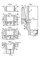
- Figure 2 provides a detailed view of the pawls 42 located just aft of the die set 22. As above, the number of pawls 42 may be increased or decreased depending on the service conditions.
- springs 44 are employed to bias the pawl 42 in a closed position 46.
- Arrow 48 depicts the pawl 42 towards the open position.
- sensing means 50 such as a limit switch, is connected to cutting means 52, such as a blade 54 or a torch.
- Control means 56 such as a microprocessor, may be employed to control the overall operation of the apparatus 10.
- the various sensors (not shown) provide information to the microprocessor 56 to enable it to simultaneously control the movement of the forming dies 22 and 24 via die control 64, the temperature of the coils 18A, 18B and 18C, the stroke of the central rod 28 and the operation of the cutting means 52.
- the apparatus and method disclosed herein further consolidates and sinters seamless tubes on a continuous basis formed from metallic powders.
- the invention is satisfactory for handling most metallic powder mixtures that are compactible by other methods.
- the invention is particularly useful for treating tubes made from ductile metal powders, such as nickel powder, cobalt powder, iron powder, copper powder, aluminum powder, magnesium powder, powders of nickel-copper alloys and powders of ductile nickel-chromium alloys, and also powders and powder mixtures of metals and alloys having suitable ductility characteristics.
- the metallic powder can comprise metal oxides and other metallic compounds including thorium oxide, aluminum oxide, magnesium oxide, silicon carbide, tungsten carbide, and yttrium oxide and other metallic dispersoids.
- the invention is particularly useful in providing accurately dimensioned and uniformly dense tubular forms.
- the range of wall thicknesses which can be further consolidated satisfactorily depends somewhat on the characteristics of the powder, the preform's history, as well as the physical displacement and positioning of the dies.
- the invention can be employed for production of tubes with other cross-sectional shapes, e.g., elliptical, rectangular, hexagonal and square configurations. It is to be especially noted that the invention provides for consolidation between rigid surfaces and thus enables close control over dimensional tolerances.
- a protective, non-oxidizing atmosphere (inert gases, reducing gases or vacuum) is maintained within the apparatus 10 via the enclosure 16.
- the front end of the tube 12 is inserted into the tube passageway 62 and into a first tube consolidation zone 58, formed between the die set 22 and the advanced mandrel 30, it is heated by the first coils 18A to the appropriate hot working or sintering temperature of the powdered alloy. See Figure 3. (Simply for discussion purposes, "advanced” means in the direction toward the inlet end or left side of Figure 1 whereas “retracted” means in the direction toward the outlet end or right side of Figure 1).
- the forming dies 22 compress the heated tube 12 about the mandrel 30 in the first tube consolidation zone 58, permitting the desired reduction in diameter and wall thickness. See Figure 4.
- the dies 22 then release and the mandrel 30 is retracted by a predetermined stroke distance via the reciprocating mechanism 38. See Figure 5.
- the mandrel 30 As the mandrel 30 is retracted, it will pull the tube 12 in the same distance as its stroke. Simultaneously, the pawls 42 will open in direction 48 allowing the just consolidated section of the tube 12 to travel with the mandrel 30.
- the second set of coils 18B heat the upsetted section of the tube 12 to cause it to radially expand and free itself from the mandrel 30.
- the mandrel 30 is then advanced back into the first tube consolidation zone 58. See Figure 6.
- the pawls 42 will close down on the tube 12 in the direction 46, thereby preventing the tube 12 from travelling backwardly with the advancing mandrel 30.
- the apparatus 10 is cocked to consolidate the next section of tube 12 adjacent to the just formed tube section 12.
- Figure 1 depicts, as a non-limiting example, two swaging stations (located around the first and second tube consolidation zones 58 and 60) comprised of the swaging dies 22 and 24 and the associated mandrels 30 and 32 and coils 18A, 18B and 18C.
- the number of components and their orientation are a function of the tubes employed, the degree of consolidation desired, and their ultimate shape.
- the consolidated tube 12 may be cut by the blade 54, if necessary.
- the member 34 is uncoupled from the junction 36 so that the blade 54 can pass through the tube 12.
- other cutting means 52 such as a torch, it may not be necessary to uncouple the member 34 from the central rod 28.
- Embodiments of the invention thus comprise an apparatus and method for consolidating and sintering a tube preform previously fabricated by powder metallurgical techniques, wherein a plurality of forming dies and movable mandrels cooperate to form a tube consolidation zone.
- One-way tube gripping means permit the tube to progress through the apparatus by the retraction of the mandrels while preventing the tube from retreating back into the consolidation zone when the mandrel is advanced. Heating coils heat the tube to sinter it and cause it to expand clear of the mandrels.
- the tube may thereby be reduced in diameter and consolidated to greater than 90% theoretical density.
Landscapes
- Engineering & Computer Science (AREA)
- Mechanical Engineering (AREA)
- Manufacturing & Machinery (AREA)
- Chemical & Material Sciences (AREA)
- Chemical Kinetics & Catalysis (AREA)
- Materials Engineering (AREA)
- Metallurgy (AREA)
- Organic Chemistry (AREA)
- Powder Metallurgy (AREA)
- Forging (AREA)
Applications Claiming Priority (2)
| Application Number | Priority Date | Filing Date | Title |
|---|---|---|---|
| US06/850,772 US4722209A (en) | 1986-04-11 | 1986-04-11 | Apparatus and method for processing powder metallurgy tubing |
| US850772 | 1986-04-11 |
Publications (1)
| Publication Number | Publication Date |
|---|---|
| EP0241833A1 true EP0241833A1 (fr) | 1987-10-21 |
Family
ID=25309076
Family Applications (1)
| Application Number | Title | Priority Date | Filing Date |
|---|---|---|---|
| EP87105052A Ceased EP0241833A1 (fr) | 1986-04-11 | 1987-04-06 | Procédé et installation pour la préparation de tubes en poudre métallique |
Country Status (3)
| Country | Link |
|---|---|
| US (1) | US4722209A (fr) |
| EP (1) | EP0241833A1 (fr) |
| JP (1) | JPS62290804A (fr) |
Cited By (4)
| Publication number | Priority date | Publication date | Assignee | Title |
|---|---|---|---|---|
| WO2015061815A1 (fr) * | 2013-10-31 | 2015-05-07 | Ceratizit Austria Gesellschaft M.B.H. | Agencement de presse avec module de retouche |
| CN107321987A (zh) * | 2017-07-21 | 2017-11-07 | 四川大学 | 多物理场耦合超快速烧结集成设备 |
| CN109648085A (zh) * | 2019-01-11 | 2019-04-19 | 武汉科技大学 | 一种高频感应辅助自蔓延NiAl系金属间化合物涂层的制备方法 |
| CN116336116A (zh) * | 2023-03-09 | 2023-06-27 | 湖南湘投轻材科技股份有限公司 | 制动盘的制备方法 |
Families Citing this family (7)
| Publication number | Priority date | Publication date | Assignee | Title |
|---|---|---|---|---|
| JPH0763798B2 (ja) * | 1987-03-18 | 1995-07-12 | 石川島播磨重工業株式会社 | 中空管の鍛造装置 |
| JPH0832351B2 (ja) * | 1989-12-29 | 1996-03-29 | アイダエンジニアリング株式会社 | フランジ部材の製造方法 |
| FI114900B (fi) * | 2000-12-20 | 2005-01-31 | Outokumpu Oy | Menetelmä ja laitteisto putkien valmistamiseksi |
| FI114901B (fi) * | 2000-12-20 | 2005-01-31 | Outokumpu Oy | Menetelmä ja laitteisto putkien valmistamiseksi valssaamalla |
| US7762114B2 (en) * | 2005-09-09 | 2010-07-27 | Applied Materials, Inc. | Flow-formed chamber component having a textured surface |
| US8935852B2 (en) * | 2008-01-04 | 2015-01-20 | Gkn Sinter Metals, Llc | Prealloyed copper powder forged connecting rod |
| DE102012106423A1 (de) * | 2012-07-17 | 2014-01-23 | Benteler Automobiltechnik Gmbh | Verfahren zur Herstellung eines Rohrstabilisators für ein Kraftfahrzeug |
Citations (4)
| Publication number | Priority date | Publication date | Assignee | Title |
|---|---|---|---|---|
| DE959998C (de) * | 1954-12-16 | 1957-03-14 | Karl Burgsmueller | Vorrichtung zur spanlosen Herstellung von Drallnuten in Laeufen von innen her |
| DE1049196B (de) * | 1941-12-05 | 1959-01-22 | Gustav Appel Maschinenfabrik | Verfahren zur Herstellung von Rohren, insbesondere von mit Zuegen versehenen Schusswaffenlaeufen, mittels einer Haemmermaschine |
| US2902714A (en) * | 1955-08-23 | 1959-09-08 | Herbert G Johnson | Rod extrusion press |
| EP0097497A2 (fr) * | 1982-06-21 | 1984-01-04 | Inco Alloys International, Inc. | Procédé et installation pour la fabrication de tubes à partir de poudre |
Family Cites Families (3)
| Publication number | Priority date | Publication date | Assignee | Title |
|---|---|---|---|---|
| FR971277A (fr) * | 1940-03-23 | 1951-01-15 | Cie Des Surchauffeurs | Procédé de façonnage de tubes par rétreint |
| US2780118A (en) * | 1953-02-05 | 1957-02-05 | United States Steel Corp | Apparatus for rolling tubes |
| US3447230A (en) * | 1967-01-05 | 1969-06-03 | Sylvania Electric Prod | Art of making seamless hollow bodies from sinterable powders |
-
1986
- 1986-04-11 US US06/850,772 patent/US4722209A/en not_active Expired - Fee Related
-
1987
- 1987-04-06 JP JP62084496A patent/JPS62290804A/ja active Granted
- 1987-04-06 EP EP87105052A patent/EP0241833A1/fr not_active Ceased
Patent Citations (4)
| Publication number | Priority date | Publication date | Assignee | Title |
|---|---|---|---|---|
| DE1049196B (de) * | 1941-12-05 | 1959-01-22 | Gustav Appel Maschinenfabrik | Verfahren zur Herstellung von Rohren, insbesondere von mit Zuegen versehenen Schusswaffenlaeufen, mittels einer Haemmermaschine |
| DE959998C (de) * | 1954-12-16 | 1957-03-14 | Karl Burgsmueller | Vorrichtung zur spanlosen Herstellung von Drallnuten in Laeufen von innen her |
| US2902714A (en) * | 1955-08-23 | 1959-09-08 | Herbert G Johnson | Rod extrusion press |
| EP0097497A2 (fr) * | 1982-06-21 | 1984-01-04 | Inco Alloys International, Inc. | Procédé et installation pour la fabrication de tubes à partir de poudre |
Cited By (6)
| Publication number | Priority date | Publication date | Assignee | Title |
|---|---|---|---|---|
| WO2015061815A1 (fr) * | 2013-10-31 | 2015-05-07 | Ceratizit Austria Gesellschaft M.B.H. | Agencement de presse avec module de retouche |
| US10695833B2 (en) | 2013-10-31 | 2020-06-30 | Ceratizit Austria Gmbh | Press arrangement with a further processing module |
| CN107321987A (zh) * | 2017-07-21 | 2017-11-07 | 四川大学 | 多物理场耦合超快速烧结集成设备 |
| CN107321987B (zh) * | 2017-07-21 | 2021-07-13 | 四川大学 | 多物理场耦合超快速烧结集成设备 |
| CN109648085A (zh) * | 2019-01-11 | 2019-04-19 | 武汉科技大学 | 一种高频感应辅助自蔓延NiAl系金属间化合物涂层的制备方法 |
| CN116336116A (zh) * | 2023-03-09 | 2023-06-27 | 湖南湘投轻材科技股份有限公司 | 制动盘的制备方法 |
Also Published As
| Publication number | Publication date |
|---|---|
| JPH0242881B2 (fr) | 1990-09-26 |
| JPS62290804A (ja) | 1987-12-17 |
| US4722209A (en) | 1988-02-02 |
Similar Documents
| Publication | Publication Date | Title |
|---|---|---|
| US4722209A (en) | Apparatus and method for processing powder metallurgy tubing | |
| RU2191652C1 (ru) | Способ получения заготовок с мелкозернистой структурой | |
| US20170081751A1 (en) | Method for producing a preform from an alpha+gamma titanium aluminide alloy for producing a component with high load-bearing capacity for piston engines and gas turbines, in particular aircraft engines | |
| US6955532B2 (en) | Method and apparatus for the manufacture of high temperature materials by combustion synthesis and semi-solid forming | |
| EP0271095A2 (fr) | Procédé pour la fabrication d'articles à partir de poudres, feuilles ou fils fins | |
| JPH0773798B2 (ja) | 永久磁石体の形成方法 | |
| EP0097497B1 (fr) | Procédé et installation pour la fabrication de tubes à partir de poudre | |
| EP0250322B1 (fr) | Procédé de fabrication d'un produit allongé fritté | |
| US3615382A (en) | Production of tubular products from metallic powders | |
| US1082933A (en) | Tungsten and method of making the same for use as filaments of incandescent electric lamps and for other purposes. | |
| WO1980001260A1 (fr) | Fabrication d'alliages a hautes performances sous forme allongee | |
| CN115780805B (zh) | 一种合金型材的立式连续增材挤压装备及制备方法 | |
| EP3205441B1 (fr) | Électrodes de soudage et procédés de fabrication de celui-ci | |
| DE3919107A1 (de) | Verfahren zur formgebung und verbesserung der mechanischen eigenschaften von pulvermetallurgisch hergestellten rohlingen aus einer legierung mit erhoehter warmfestigkeit durch strangpressen | |
| US3987658A (en) | Graphite forging die | |
| US3919875A (en) | Method of and apparatus for making high pressure tube bends, especially for the chemical industry | |
| CN101612638A (zh) | 半固态金属坯料二次加热用卧式装置 | |
| US10300531B2 (en) | Methods of manufacturing composite materials, composite wires, and welding electrodes | |
| JPS6137341A (ja) | 異形断面形状を有する閉塞鍛造用荒地素材の製造装置 | |
| US3231373A (en) | Production of high density compacts | |
| US3180024A (en) | Metal working process and apparatus | |
| EP0570801A1 (fr) | Procédé de fabrication d'un tube métallique sans cordon | |
| Rozner et al. | Powder Metallurgy for Fabrication of Wire-Reinforced Advanced Gas Turbine Components | |
| US3199331A (en) | Process for the extrusion of ultra-fine wires | |
| JPH10225759A (ja) | 金属地複合体を製造する装置および方法 |
Legal Events
| Date | Code | Title | Description |
|---|---|---|---|
| PUAI | Public reference made under article 153(3) epc to a published international application that has entered the european phase |
Free format text: ORIGINAL CODE: 0009012 |
|
| AK | Designated contracting states |
Kind code of ref document: A1 Designated state(s): DE FR GB IT SE |
|
| 17P | Request for examination filed |
Effective date: 19880212 |
|
| 17Q | First examination report despatched |
Effective date: 19890720 |
|
| STAA | Information on the status of an ep patent application or granted ep patent |
Free format text: STATUS: THE APPLICATION HAS BEEN REFUSED |
|
| 18R | Application refused |
Effective date: 19900906 |
|
| RIN1 | Information on inventor provided before grant (corrected) |
Inventor name: MANKINS, WILLIAM LAWRENCE |