EP0241402A2 - Installation d'éclairage avec plusieurs éléments d'éclairage - Google Patents
Installation d'éclairage avec plusieurs éléments d'éclairage Download PDFInfo
- Publication number
- EP0241402A2 EP0241402A2 EP87500014A EP87500014A EP0241402A2 EP 0241402 A2 EP0241402 A2 EP 0241402A2 EP 87500014 A EP87500014 A EP 87500014A EP 87500014 A EP87500014 A EP 87500014A EP 0241402 A2 EP0241402 A2 EP 0241402A2
- Authority
- EP
- European Patent Office
- Prior art keywords
- lids
- lid
- components
- lighting installations
- bodies
- Prior art date
- Legal status (The legal status is an assumption and is not a legal conclusion. Google has not performed a legal analysis and makes no representation as to the accuracy of the status listed.)
- Granted
Links
- 238000009434 installation Methods 0.000 title claims description 19
- 230000000295 complement effect Effects 0.000 claims abstract description 11
- 239000000725 suspension Substances 0.000 claims abstract 3
- 230000013011 mating Effects 0.000 claims description 3
- 238000010276 construction Methods 0.000 claims 1
- 239000000306 component Substances 0.000 description 17
- 230000008878 coupling Effects 0.000 description 3
- 238000010168 coupling process Methods 0.000 description 3
- 238000005859 coupling reaction Methods 0.000 description 3
- -1 ballasts Substances 0.000 description 2
- 239000000969 carrier Substances 0.000 description 2
- 210000002105 tongue Anatomy 0.000 description 2
- 238000004873 anchoring Methods 0.000 description 1
- 238000005286 illumination Methods 0.000 description 1
- 230000037431 insertion Effects 0.000 description 1
- 238000003780 insertion Methods 0.000 description 1
- 230000003287 optical effect Effects 0.000 description 1
- 229920000136 polysorbate Polymers 0.000 description 1
Images


Classifications
-
- F—MECHANICAL ENGINEERING; LIGHTING; HEATING; WEAPONS; BLASTING
- F21—LIGHTING
- F21S—NON-PORTABLE LIGHTING DEVICES; SYSTEMS THEREOF; VEHICLE LIGHTING DEVICES SPECIALLY ADAPTED FOR VEHICLE EXTERIORS
- F21S2/00—Systems of lighting devices, not provided for in main groups F21S4/00 - F21S10/00 or F21S19/00, e.g. of modular construction
- F21S2/005—Systems of lighting devices, not provided for in main groups F21S4/00 - F21S10/00 or F21S19/00, e.g. of modular construction of modular construction
-
- F—MECHANICAL ENGINEERING; LIGHTING; HEATING; WEAPONS; BLASTING
- F21—LIGHTING
- F21S—NON-PORTABLE LIGHTING DEVICES; SYSTEMS THEREOF; VEHICLE LIGHTING DEVICES SPECIALLY ADAPTED FOR VEHICLE EXTERIORS
- F21S8/00—Lighting devices intended for fixed installation
- F21S8/04—Lighting devices intended for fixed installation intended only for mounting on a ceiling or the like overhead structures
- F21S8/06—Lighting devices intended for fixed installation intended only for mounting on a ceiling or the like overhead structures by suspension
-
- F—MECHANICAL ENGINEERING; LIGHTING; HEATING; WEAPONS; BLASTING
- F21—LIGHTING
- F21V—FUNCTIONAL FEATURES OR DETAILS OF LIGHTING DEVICES OR SYSTEMS THEREOF; STRUCTURAL COMBINATIONS OF LIGHTING DEVICES WITH OTHER ARTICLES, NOT OTHERWISE PROVIDED FOR
- F21V15/00—Protecting lighting devices from damage
- F21V15/01—Housings, e.g. material or assembling of housing parts
- F21V15/013—Housings, e.g. material or assembling of housing parts the housing being an extrusion
-
- F—MECHANICAL ENGINEERING; LIGHTING; HEATING; WEAPONS; BLASTING
- F21—LIGHTING
- F21V—FUNCTIONAL FEATURES OR DETAILS OF LIGHTING DEVICES OR SYSTEMS THEREOF; STRUCTURAL COMBINATIONS OF LIGHTING DEVICES WITH OTHER ARTICLES, NOT OTHERWISE PROVIDED FOR
- F21V15/00—Protecting lighting devices from damage
- F21V15/01—Housings, e.g. material or assembling of housing parts
- F21V15/015—Devices for covering joints between adjacent lighting devices; End coverings
-
- F—MECHANICAL ENGINEERING; LIGHTING; HEATING; WEAPONS; BLASTING
- F21—LIGHTING
- F21V—FUNCTIONAL FEATURES OR DETAILS OF LIGHTING DEVICES OR SYSTEMS THEREOF; STRUCTURAL COMBINATIONS OF LIGHTING DEVICES WITH OTHER ARTICLES, NOT OTHERWISE PROVIDED FOR
- F21V21/00—Supporting, suspending, or attaching arrangements for lighting devices; Hand grips
- F21V21/005—Supporting, suspending, or attaching arrangements for lighting devices; Hand grips for several lighting devices in an end-to-end arrangement, i.e. light tracks
-
- F—MECHANICAL ENGINEERING; LIGHTING; HEATING; WEAPONS; BLASTING
- F21—LIGHTING
- F21V—FUNCTIONAL FEATURES OR DETAILS OF LIGHTING DEVICES OR SYSTEMS THEREOF; STRUCTURAL COMBINATIONS OF LIGHTING DEVICES WITH OTHER ARTICLES, NOT OTHERWISE PROVIDED FOR
- F21V23/00—Arrangement of electric circuit elements in or on lighting devices
- F21V23/06—Arrangement of electric circuit elements in or on lighting devices the elements being coupling devices, e.g. connectors
-
- F—MECHANICAL ENGINEERING; LIGHTING; HEATING; WEAPONS; BLASTING
- F21—LIGHTING
- F21V—FUNCTIONAL FEATURES OR DETAILS OF LIGHTING DEVICES OR SYSTEMS THEREOF; STRUCTURAL COMBINATIONS OF LIGHTING DEVICES WITH OTHER ARTICLES, NOT OTHERWISE PROVIDED FOR
- F21V17/00—Fastening of component parts of lighting devices, e.g. shades, globes, refractors, reflectors, filters, screens, grids or protective cages
- F21V17/10—Fastening of component parts of lighting devices, e.g. shades, globes, refractors, reflectors, filters, screens, grids or protective cages characterised by specific fastening means or way of fastening
- F21V17/16—Fastening of component parts of lighting devices, e.g. shades, globes, refractors, reflectors, filters, screens, grids or protective cages characterised by specific fastening means or way of fastening by deformation of parts; Snap action mounting
- F21V17/164—Fastening of component parts of lighting devices, e.g. shades, globes, refractors, reflectors, filters, screens, grids or protective cages characterised by specific fastening means or way of fastening by deformation of parts; Snap action mounting the parts being subjected to bending, e.g. snap joints
-
- F—MECHANICAL ENGINEERING; LIGHTING; HEATING; WEAPONS; BLASTING
- F21—LIGHTING
- F21V—FUNCTIONAL FEATURES OR DETAILS OF LIGHTING DEVICES OR SYSTEMS THEREOF; STRUCTURAL COMBINATIONS OF LIGHTING DEVICES WITH OTHER ARTICLES, NOT OTHERWISE PROVIDED FOR
- F21V23/00—Arrangement of electric circuit elements in or on lighting devices
- F21V23/02—Arrangement of electric circuit elements in or on lighting devices the elements being transformers, impedances or power supply units, e.g. a transformer with a rectifier
- F21V23/026—Fastening of transformers or ballasts
-
- F—MECHANICAL ENGINEERING; LIGHTING; HEATING; WEAPONS; BLASTING
- F21—LIGHTING
- F21V—FUNCTIONAL FEATURES OR DETAILS OF LIGHTING DEVICES OR SYSTEMS THEREOF; STRUCTURAL COMBINATIONS OF LIGHTING DEVICES WITH OTHER ARTICLES, NOT OTHERWISE PROVIDED FOR
- F21V27/00—Cable-stowing arrangements structurally associated with lighting devices, e.g. reels
-
- F—MECHANICAL ENGINEERING; LIGHTING; HEATING; WEAPONS; BLASTING
- F21—LIGHTING
- F21Y—INDEXING SCHEME ASSOCIATED WITH SUBCLASSES F21K, F21L, F21S and F21V, RELATING TO THE FORM OR THE KIND OF THE LIGHT SOURCES OR OF THE COLOUR OF THE LIGHT EMITTED
- F21Y2103/00—Elongate light sources, e.g. fluorescent tubes
-
- F—MECHANICAL ENGINEERING; LIGHTING; HEATING; WEAPONS; BLASTING
- F21—LIGHTING
- F21Y—INDEXING SCHEME ASSOCIATED WITH SUBCLASSES F21K, F21L, F21S and F21V, RELATING TO THE FORM OR THE KIND OF THE LIGHT SOURCES OR OF THE COLOUR OF THE LIGHT EMITTED
- F21Y2113/00—Combination of light sources
Definitions
- the present invention relates to a set of assemblable components for making up lighting apparatus or installations, with the use of which it is possible to implement installations that can be suited to the specific requirements of every case of application, starting from some components allowing several combinations to be performed.
- the equipment according to the invention is essentially comprised of boxes formed starting from channel profiled members having means for pressure fitting with one another in order to conform the box, at least one of these profiles being translucent.
- These profiled members show internal housings for conduction leads, as well as longitudinal grooves for anchoring of screw threaded bolts for affixing several components (lamp carriers, ballasts, primers, etc.).
- the ends of these boxes receive respective lids formed with means for engagement and electrical connection with other means provided on lids of complementary boxes.
- Terminal boxes, with no electrical connections, have been provided for the terminal ends of bodies placed at the ends of the ensemble of components fitted together.
- the set of components comprises junction-like bodies for connection and bifurcation of other boxes or bodies, the junctions being provided with an optional number of adjustable couplings and connections mating with the couplings and connections of the above boxes.
- the coupling means of the lids of the hollow bodies containing the lighting devices are formed with coaxial half-sleeves of different radius and protruding from their outer surfaces, which are complementary of those of an adjacent lid to form a cavity which surrounds a plurality of tubular housings wherein electric connection sockets and pins are placed, the connection sockets and pins of one lid being adapted for fitting with those of the lid of an adjacent body to be joined, the said electric connection sockets and pins being provided with connection tongues protruding towards the center of an opening formed on the lid, to receive the feeding electric cables.
- one of the half-sleeves of the lids has mating semicircular cutouts at diametrically opposite points, so that, when the lid of a box is coupled with the lid of an adjacent one with all of the half-sleeves coaxial, the cutouts of one lid match with those of the other lid and define openings through which removable locking pins are threaded to ensure the lid engagement.
- the locking pins are of a tubular structure to form a passageway for supporting struts.
- the terminal lid itself shows a protruding, closed extension having an outline similar to that of the half-sleeves of the connection and assembling lids, with opposite circular holes for engagement of a tubular locking pin intended to receive a supporting strut.
- connection and engagement lids as well as the terminal lids have projections on their internal face in order to facilitate centering of the lid as regards the end of the box where they are fixed to, as well as holes for securing screws, the said holes being faced to housings formed in the profiled members making up the box and arranged for threaded engagement of the above screws.
- lids for assembling between two boxes have the sets of pins and sockets offset 90° as regards the sets of the other boxes, in order to locate said boxes in a position offset to an angle as well.
- the boxes may, likewise, be rotationally movable for directing the light as desired.
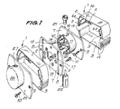
- figure 1 is a perspective view of the channeled profiled members making up the luminous boxes or container boxes for the electrical components of the equipment, the lids for assembly or engagement of the boxes and a terminal lid, in dismantled showing;
- figure 2 is a perspective view of one of the boxes with neither lids nor electrical components inside them;
- figure 3 is an elevation view of the outer face of one of the assembly and connection lids, the figure showing as well, in dotted lines, the position of one lid with the same half-sleeves and connection, though in a position which is offset 90° as regards the position shown in solid lines;
- figure 4 is a view in longitudinal section of two assembly and connection lids shown in separated relation;
- figure 5 is a similar view of the two lids assembled with one another;
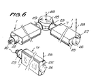
- figure 6 is a perspective view showing a mounted set of equipment components;
- figure 7 is an elevation view of several components in assembled condition, and
- figure 8 is a diagrammatic plan view of the equipment as installed according to an
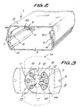
- the equipment of assemblable components for lighting installations shown in the drawings is made up of boxes generally referred to with 1 and formed of two profiled members 2 and 3, of generally channeled shape and mutually complementary, the edges of the said members having sets of ribs and grooves 4 for their mutual pressure fitting (Fig. 2).
- the profiled member 3 may be translucent in the case that a luminous tube is housed therein.
- the inside of the profiled members 2 and 3 is formed with longitudinal grooves 5 in ribs or wings 6 where the screws for securing the electrical components such as lamp carriers, ballasts, primers and other, are fastened to.
- the profiled members have, as well, lips 6a for housing the electrical cables.
- a lid 7 is engaged at each end of the boxes 1 and is formed with ribs 8 for guiding their position, as well as holes 9 through which screws 10 are passed for screw threaded engagement with the ends 5a of the grooves 5, in order to secure the lids.
- the outer face of the lids 7 has two mutually complementary, diametrically opposite half-sleeves 11 and 12 of different radius, which surround sets of mutually complementary sleeves or tubular housings 13 and 14 which receive, respectively, connection sockets 15 and pins 16 provided with tongues 17 directed towards the center of a central opening 18 of the respective lid for connection to the electric installation cables.
- the half-sleeves 11 have pairs of semicircular. complementary and opposite cutouts 19 and 20 which mate with one another when the half-sleeves of one lid are fitted or assembled with those of a like lid (Fig. 5).
- the openings formed by the mated cutouts 19 and 20 serve to form a passageway for locking pins 21 and 22 having axial holes 23 through which supporting cables or struts 24 can be inserted.
- the locking pins 21,22 play the role of a linkage between two contiguous lids and ensure the stillness of these later.
- the equipment comprises as well terminal lids 25 having an outline which is analogous to that of the lids 7, and a small closed outer box 26 of a shape similar to that of the half-sleeves 11 and 12, and formed with openings 27 which are similar to the openings 19 and 20 to provide for the insertion of locking pins 21 and 22 in order to secure the ends of suspending struts 23.
- the half-sleeves 11 and 12 are located offset 90° as regards their usual position, for example as indicated with doted lines in figure 3, to place a box 1a in a position which is offset 90° as regards the other boxes (Fig. 6 and 7).
- the equipment comprises as well distribution or junction bodies 28 provided with connection sleeves 29 having a shape which is complementary to that of the half-sleeves 11 and 12 of the assembly lids 7, and provided with electric connection sockets and pins.
- the connection sleeves 29 have a tail 30 shaped so that it can be removably trapped in the junction body 28 and allow the body 29 to be placed in the suitable position.
- the body 28 can trap two or more tails 30 or respective sleeves 29, according to the needs of the installation (Fig. 8).
- the above junction body 28 comprises means for securing a suspending strut 23, as well as for mounting a swinging spotlight 31 of a conventional shape (Fig. 6).
- the equipment of assemblable components allows multiple combinations to be effected in or der to attain an illumination layout which is distributed in a manner suitable to the features of the site to be lighted, starting from a small series of invariable components featuring an ability for being assembled in different ways.
- This equipment can be completed with an articultion device joined to the profiled members so that these latter can be directed in whatever direction. It is foreseen as well a flexible articulation that can be assembled to the profiled members in order to place the luminous tubes in a vertical plane.
Landscapes
- Engineering & Computer Science (AREA)
- General Engineering & Computer Science (AREA)
- Circuit Arrangement For Electric Light Sources In General (AREA)
- Non-Portable Lighting Devices Or Systems Thereof (AREA)
- Fastening Of Light Sources Or Lamp Holders (AREA)
Priority Applications (1)
| Application Number | Priority Date | Filing Date | Title |
|---|---|---|---|
| AT87500014T ATE85680T1 (de) | 1986-04-09 | 1987-04-07 | Beleuchtungssystem mit mehreren beleuchtungseinheiten. |
Applications Claiming Priority (2)
| Application Number | Priority Date | Filing Date | Title |
|---|---|---|---|
| ES1986293470U ES293470Y (es) | 1986-04-09 | 1986-04-09 | Equipo de componentes ensamblables para iluminacion |
| ES293470 | 1986-04-09 |
Publications (3)
| Publication Number | Publication Date |
|---|---|
| EP0241402A2 true EP0241402A2 (fr) | 1987-10-14 |
| EP0241402A3 EP0241402A3 (en) | 1989-04-05 |
| EP0241402B1 EP0241402B1 (fr) | 1993-02-10 |
Family
ID=8440584
Family Applications (1)
| Application Number | Title | Priority Date | Filing Date |
|---|---|---|---|
| EP87500014A Expired - Lifetime EP0241402B1 (fr) | 1986-04-09 | 1987-04-07 | Installation d'éclairage avec plusieurs éléments d'éclairage |
Country Status (4)
| Country | Link |
|---|---|
| EP (1) | EP0241402B1 (fr) |
| AT (1) | ATE85680T1 (fr) |
| DE (1) | DE3784089T2 (fr) |
| ES (1) | ES293470Y (fr) |
Cited By (3)
| Publication number | Priority date | Publication date | Assignee | Title |
|---|---|---|---|---|
| DE3912299A1 (de) * | 1989-04-14 | 1990-11-29 | Joerg Michael Uhl | Leuchtroehrenanordnungs- und betriebssystem |
| EP0877198A3 (fr) * | 1997-05-06 | 2000-12-20 | Keller Lichtsysteme GmbH | Dispositif d'éclairage |
| DE10139336B4 (de) * | 2001-08-10 | 2012-04-26 | Hartmut S. Engel | Modulares Leuchtensystem |
Family Cites Families (5)
| Publication number | Priority date | Publication date | Assignee | Title |
|---|---|---|---|---|
| GB561090A (en) * | 1942-01-07 | 1944-05-04 | Darwin Curtis | Improvements in electric lighting fixtures |
| AT308239B (de) * | 1970-07-08 | 1973-06-25 | Anton Brenner Ing | Leuchtkörper |
| DE2556813B2 (de) * | 1975-12-17 | 1979-12-13 | Wolfgang 6204 Taunusstein Fenner | Raumfachwerk |
| US4096379A (en) * | 1976-08-24 | 1978-06-20 | Albert Taylor | Modular illumination device |
| DE3014241A1 (de) * | 1980-04-14 | 1981-11-12 | Trilux-Lenze Gmbh + Co Kg, 5760 Arnsberg | Vorrichtung zum verbinden von leuchten zu lichtbaendern bzw. lichtbandfiguren |
-
1986
- 1986-04-09 ES ES1986293470U patent/ES293470Y/es not_active Expired
-
1987
- 1987-04-07 DE DE8787500014T patent/DE3784089T2/de not_active Expired - Fee Related
- 1987-04-07 EP EP87500014A patent/EP0241402B1/fr not_active Expired - Lifetime
- 1987-04-07 AT AT87500014T patent/ATE85680T1/de not_active IP Right Cessation
Cited By (3)
| Publication number | Priority date | Publication date | Assignee | Title |
|---|---|---|---|---|
| DE3912299A1 (de) * | 1989-04-14 | 1990-11-29 | Joerg Michael Uhl | Leuchtroehrenanordnungs- und betriebssystem |
| EP0877198A3 (fr) * | 1997-05-06 | 2000-12-20 | Keller Lichtsysteme GmbH | Dispositif d'éclairage |
| DE10139336B4 (de) * | 2001-08-10 | 2012-04-26 | Hartmut S. Engel | Modulares Leuchtensystem |
Also Published As
| Publication number | Publication date |
|---|---|
| EP0241402B1 (fr) | 1993-02-10 |
| ES293470U (es) | 1986-08-01 |
| DE3784089T2 (de) | 1993-08-05 |
| EP0241402A3 (en) | 1989-04-05 |
| ES293470Y (es) | 1987-04-16 |
| DE3784089D1 (de) | 1993-03-25 |
| ATE85680T1 (de) | 1993-02-15 |
Similar Documents
| Publication | Publication Date | Title |
|---|---|---|
| US5073845A (en) | Fluorescent retrofit light fixture | |
| US7401942B1 (en) | Female electric connector plug apparatus for and method of attachment to flourescent tube luminaire fixture assembly | |
| CN101160541B (zh) | 光纤/铜混合连接器的系统和方法 | |
| US2988633A (en) | Fluorescent ceiling light fixture assembly | |
| US20070091596A1 (en) | Modular lighting system and method of installation | |
| EP0240054A1 (fr) | Armature lumineuse avec anneau de fixation divisible | |
| US20060152933A1 (en) | Illumination device | |
| EP0241402A2 (fr) | Installation d'éclairage avec plusieurs éléments d'éclairage | |
| CA2212156A1 (fr) | Appareil d'eclairage allonge | |
| CA2089444A1 (fr) | Dispositif de retenue d'ampoule | |
| AU2001248323B2 (en) | Built-in lamp with a dome-shaped reflector | |
| US5221138A (en) | Serial light fixture | |
| US4841418A (en) | Explosion-proof fixture and method | |
| US2964616A (en) | Lighting fixture | |
| EP0396784A1 (fr) | Système d'accrochage rapide pour luminaire complet, pour l'accrochage rapide de lampes, d'abats-jours et de luminaires | |
| EP0469179B1 (fr) | Système d'éclairage modulaire | |
| EP0089713B1 (fr) | Armature lumineuse | |
| EP1016818A3 (fr) | Douille de lampe en matière isolante pour lampes H7 | |
| EP0664584B1 (fr) | Douille pour lampe à incandescence | |
| US6413107B1 (en) | Lamp | |
| US3465282A (en) | Light fitting | |
| US3018363A (en) | Lighting fixture | |
| US20050277321A1 (en) | Adapter apparatus for fluorescent lamp fixtures | |
| GB2064089A (en) | Improvements in or relating to lighting apparatus | |
| EP0614042A1 (fr) | Segment pour chemin d'éclairage et chemin d'éclairage équipé d'un tel segment |
Legal Events
| Date | Code | Title | Description |
|---|---|---|---|
| PUAI | Public reference made under article 153(3) epc to a published international application that has entered the european phase |
Free format text: ORIGINAL CODE: 0009012 |
|
| AK | Designated contracting states |
Kind code of ref document: A2 Designated state(s): AT BE CH DE FR GB GR IT LI LU NL SE |
|
| PUAL | Search report despatched |
Free format text: ORIGINAL CODE: 0009013 |
|
| AK | Designated contracting states |
Kind code of ref document: A3 Designated state(s): AT BE CH DE FR GB GR IT LI LU NL SE |
|
| 17P | Request for examination filed |
Effective date: 19891006 |
|
| 17Q | First examination report despatched |
Effective date: 19910822 |
|
| RTI1 | Title (correction) | ||
| GRAA | (expected) grant |
Free format text: ORIGINAL CODE: 0009210 |
|
| AK | Designated contracting states |
Kind code of ref document: B1 Designated state(s): AT BE CH DE FR GB GR IT LI LU NL SE |
|
| REF | Corresponds to: |
Ref document number: 85680 Country of ref document: AT Date of ref document: 19930215 Kind code of ref document: T |
|
| REF | Corresponds to: |
Ref document number: 3784089 Country of ref document: DE Date of ref document: 19930325 |
|
| PGFP | Annual fee paid to national office [announced via postgrant information from national office to epo] |
Ref country code: SE Payment date: 19930413 Year of fee payment: 7 |
|
| PGFP | Annual fee paid to national office [announced via postgrant information from national office to epo] |
Ref country code: DE Payment date: 19930419 Year of fee payment: 7 Ref country code: AT Payment date: 19930419 Year of fee payment: 7 |
|
| PGFP | Annual fee paid to national office [announced via postgrant information from national office to epo] |
Ref country code: LU Payment date: 19930421 Year of fee payment: 7 |
|
| PGFP | Annual fee paid to national office [announced via postgrant information from national office to epo] |
Ref country code: FR Payment date: 19930429 Year of fee payment: 7 |
|
| PGFP | Annual fee paid to national office [announced via postgrant information from national office to epo] |
Ref country code: NL Payment date: 19930430 Year of fee payment: 7 Ref country code: GB Payment date: 19930430 Year of fee payment: 7 |
|
| ITF | It: translation for a ep patent filed | ||
| PGFP | Annual fee paid to national office [announced via postgrant information from national office to epo] |
Ref country code: BE Payment date: 19930504 Year of fee payment: 7 |
|
| PGFP | Annual fee paid to national office [announced via postgrant information from national office to epo] |
Ref country code: GR Payment date: 19930510 Year of fee payment: 7 |
|
| PGFP | Annual fee paid to national office [announced via postgrant information from national office to epo] |
Ref country code: CH Payment date: 19930527 Year of fee payment: 7 |
|
| ET | Fr: translation filed | ||
| REG | Reference to a national code |
Ref country code: GR Ref legal event code: FG4A Free format text: 3007786 |
|
| EPTA | Lu: last paid annual fee | ||
| PLBE | No opposition filed within time limit |
Free format text: ORIGINAL CODE: 0009261 |
|
| STAA | Information on the status of an ep patent application or granted ep patent |
Free format text: STATUS: NO OPPOSITION FILED WITHIN TIME LIMIT |
|
| 26N | No opposition filed | ||
| PG25 | Lapsed in a contracting state [announced via postgrant information from national office to epo] |
Ref country code: LU Free format text: LAPSE BECAUSE OF NON-PAYMENT OF DUE FEES Effective date: 19940407 Ref country code: GB Effective date: 19940407 Ref country code: AT Effective date: 19940407 |
|
| PG25 | Lapsed in a contracting state [announced via postgrant information from national office to epo] |
Ref country code: SE Effective date: 19940408 |
|
| PG25 | Lapsed in a contracting state [announced via postgrant information from national office to epo] |
Ref country code: LI Effective date: 19940430 Ref country code: CH Effective date: 19940430 Ref country code: BE Effective date: 19940430 |
|
| BERE | Be: lapsed |
Owner name: S.A. J. FELIU DE LA PENA Effective date: 19940430 |
|
| PG25 | Lapsed in a contracting state [announced via postgrant information from national office to epo] |
Ref country code: GR Free format text: THE PATENT HAS BEEN ANNULLED BY A DECISION OF A NATIONAL AUTHORITY Effective date: 19941031 |
|
| PG25 | Lapsed in a contracting state [announced via postgrant information from national office to epo] |
Ref country code: NL Effective date: 19941101 |
|
| GBPC | Gb: european patent ceased through non-payment of renewal fee |
Effective date: 19940407 |
|
| NLV4 | Nl: lapsed or anulled due to non-payment of the annual fee | ||
| PG25 | Lapsed in a contracting state [announced via postgrant information from national office to epo] |
Ref country code: FR Effective date: 19941229 |
|
| REG | Reference to a national code |
Ref country code: CH Ref legal event code: PL |
|
| PG25 | Lapsed in a contracting state [announced via postgrant information from national office to epo] |
Ref country code: DE Effective date: 19950103 |
|
| EUG | Se: european patent has lapsed |
Ref document number: 87500014.3 Effective date: 19941110 |
|
| REG | Reference to a national code |
Ref country code: FR Ref legal event code: ST |
|
| REG | Reference to a national code |
Ref country code: GR Ref legal event code: MM2A Free format text: 3007786 |
|
| PG25 | Lapsed in a contracting state [announced via postgrant information from national office to epo] |
Ref country code: IT Free format text: LAPSE BECAUSE OF NON-PAYMENT OF DUE FEES;WARNING: LAPSES OF ITALIAN PATENTS WITH EFFECTIVE DATE BEFORE 2007 MAY HAVE OCCURRED AT ANY TIME BEFORE 2007. THE CORRECT EFFECTIVE DATE MAY BE DIFFERENT FROM THE ONE RECORDED. Effective date: 20050407 |