EP0241360B1 - Fixation de sécurité pour ski - Google Patents
Fixation de sécurité pour ski Download PDFInfo
- Publication number
- EP0241360B1 EP0241360B1 EP87400734A EP87400734A EP0241360B1 EP 0241360 B1 EP0241360 B1 EP 0241360B1 EP 87400734 A EP87400734 A EP 87400734A EP 87400734 A EP87400734 A EP 87400734A EP 0241360 B1 EP0241360 B1 EP 0241360B1
- Authority
- EP
- European Patent Office
- Prior art keywords
- jaw
- rod
- unit
- support
- plate
- Prior art date
- Legal status (The legal status is an assumption and is not a legal conclusion. Google has not performed a legal analysis and makes no representation as to the accuracy of the status listed.)
- Expired
Links
Images

Classifications
-
- A—HUMAN NECESSITIES
- A63—SPORTS; GAMES; AMUSEMENTS
- A63C—SKATES; SKIS; ROLLER SKATES; DESIGN OR LAYOUT OF COURTS, RINKS OR THE LIKE
- A63C9/00—Ski bindings
- A63C9/08—Ski bindings yieldable or self-releasing in the event of an accident, i.e. safety bindings
- A63C9/085—Ski bindings yieldable or self-releasing in the event of an accident, i.e. safety bindings with sole hold-downs, e.g. swingable
- A63C9/08535—Ski bindings yieldable or self-releasing in the event of an accident, i.e. safety bindings with sole hold-downs, e.g. swingable with a mobile body or base or single jaw
- A63C9/08542—Ski bindings yieldable or self-releasing in the event of an accident, i.e. safety bindings with sole hold-downs, e.g. swingable with a mobile body or base or single jaw pivoting about a transversal axis
-
- A—HUMAN NECESSITIES
- A63—SPORTS; GAMES; AMUSEMENTS
- A63C—SKATES; SKIS; ROLLER SKATES; DESIGN OR LAYOUT OF COURTS, RINKS OR THE LIKE
- A63C9/00—Ski bindings
- A63C9/08—Ski bindings yieldable or self-releasing in the event of an accident, i.e. safety bindings
- A63C9/085—Ski bindings yieldable or self-releasing in the event of an accident, i.e. safety bindings with sole hold-downs, e.g. swingable
- A63C9/08535—Ski bindings yieldable or self-releasing in the event of an accident, i.e. safety bindings with sole hold-downs, e.g. swingable with a mobile body or base or single jaw
- A63C9/0855—Ski bindings yieldable or self-releasing in the event of an accident, i.e. safety bindings with sole hold-downs, e.g. swingable with a mobile body or base or single jaw pivoting about a vertical axis
-
- A—HUMAN NECESSITIES
- A63—SPORTS; GAMES; AMUSEMENTS
- A63C—SKATES; SKIS; ROLLER SKATES; DESIGN OR LAYOUT OF COURTS, RINKS OR THE LIKE
- A63C9/00—Ski bindings
- A63C9/08—Ski bindings yieldable or self-releasing in the event of an accident, i.e. safety bindings
- A63C9/085—Ski bindings yieldable or self-releasing in the event of an accident, i.e. safety bindings with sole hold-downs, e.g. swingable
- A63C9/08557—Details of the release mechanism
- A63C9/08564—Details of the release mechanism using cam or slide surface
-
- A—HUMAN NECESSITIES
- A63—SPORTS; GAMES; AMUSEMENTS
- A63C—SKATES; SKIS; ROLLER SKATES; DESIGN OR LAYOUT OF COURTS, RINKS OR THE LIKE
- A63C9/00—Ski bindings
- A63C9/001—Anti-friction devices
-
- A—HUMAN NECESSITIES
- A63—SPORTS; GAMES; AMUSEMENTS
- A63C—SKATES; SKIS; ROLLER SKATES; DESIGN OR LAYOUT OF COURTS, RINKS OR THE LIKE
- A63C9/00—Ski bindings
- A63C9/08—Ski bindings yieldable or self-releasing in the event of an accident, i.e. safety bindings
- A63C9/0805—Adjustment of the toe or heel holders; Indicators therefor
Definitions
- the present invention relates to ski safety bindings which are adapted to immobilize the front of a shoe by constituting a front stop.
- the invention relates to the so-called "multidirectional tripping" front stops which comprise a retaining jaw, mounted movable in different directions, while being held in its normal position by an elastic retaining mechanism.
- the jaw in the event of torsion acting on the foot, the jaw can move laterally in order to allow the shoe to escape. However, this jaw can also move upward to allow the shoe to escape in this direction in the event of the skier falling back. Furthermore, the jaw of certain front stops is mounted so as to be able to move in all directions in order to release the boot in optimum conditions in the event of a complex fall, that is to say in the case of a fall combining a torsional force with an upward extension force, or even in the case of a fall backwards accompanied by a torsional force.
- some front fixation stops are designed so that a thrust of the shoe forward, due for example to the beginning of a fall forward, causes a reduction in the elastic resistance opposing the rotation of the body of the corresponding stop. Indeed, such a thrust increases the friction of the shoe and consequently the hardness in the exhaust.
- the elastic resistance of the retaining mechanism should therefore be reduced so that the magnitude of the retaining force remains substantially the same.
- patent FR-A 2,395,046 describes a front stop whose retaining jaw is slidably mounted in the axial direction on the rotary body thereof so as to ensure a reduction in the elastic torsional resistance in the event that a thrust is exerted on this jaw forward.
- the elastic mechanism provided in this stop consists of a piston housed inside the rotary body and which is applied by a spring against a flat provided on the pivot thereof.
- this piston carries two lateral extensions, arranged on either side of the pivot, and against the ends of which the retaining jaw acts in the event of its movement forward. This then causes the spacing of this piston relative to the flat which it normally serves as a seat, which allows free rotation of the body of the stop.
- patent FR-A 2,439,601 describes a binding which can as well constitute a heel piece as a front stop and whose design allows an escape from the corresponding end of the shoe upwards, which does not The above mentioned front stop is not.
- the binding described in this second patent comprises an endpiece capable of pivoting upward and which is carried by a body itself rotatably mounted around a pivot perpendicular to the ski.
- This pivot has two flats oriented in opposite directions and against which are respectively applied a bearing surface provided in the bottom of the rotary body and a piston mounted inside the latter, a single spring pressing on this piston.
- the corresponding jaw is pivotally mounted directly on the rotary body of the binding and this, around a transverse axis, parallel to the upper surface of the ski.
- this jaw is held in its normal position by a transverse rod interposed between the bottom of the rotary body and the corresponding flat part of the pivot, and the ends of which cooperate with ramps provided on this jaw.
- the aim of the present invention is to produce a front stop with multidirectional triggering, the design of which is such that it can release the front of the shoe under the best possible conditions of safety in the various cases which may occur.
- the design of this stop is such that its arrangement and structure are much simpler than in existing stops with multidirectional release.
- the structure of the present stop is extremely simple and nevertheless it is able to ensure the release of the front of the shoe in all the desired directions and this, under the best possible conditions to ensure very good security.
- the planned arrangement makes it possible to produce cams and support plates having parts of different widths so that the elastic resistance, opposed to the movement of the retaining jaw, is of different value depending on the type of movement it undergoes.
- the resistance to lateral release is reduced by the fact that the thrust exerted by the shoe on the jaw makes it move back while relieving the pressure exerted by it against the corresponding flat part of the support. fixed.
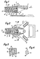
- the stop according to the invention comprises a retaining jaw whose movable body is designated by the general reference 1. At its rear end, it carries two arms 2 intended to frame the front end of the shoe to immobilize. As for the front part of the body of this jaw, it contains the various organs of the elastic mechanism ensuring its immobilization in its normal position.
- This jaw is movably mounted on a fixed support constituted by a plate 3 carried by a mounting plate 4. This last is intended to be fixed on the upper surface of a ski, for example by means of screws.
- the plate 3 extends perpendicular to this plate so that after mounting, it is arranged perpendicular to the surface of the ski. Furthermore, both sides 5 and 6 of this plate are then arranged in planes transverse to the X-Y axis of the assembly, therefore, after assembly, to the longitudinal axis of the ski.
- the two faces of the plate 3 constitute two flats forming part of the elastic mechanism ensuring the maintenance of the body 1 of the jaw in its normal position.
- This mechanism also comprises two flat cams which are applied against these flats by a single coil spring 7.
- One of these cams is constituted by a bearing surface 8 formed on the body 1 of the retaining jaw and which is oriented rearward, that is to say towards the location of the shoe, so as to be applied against the flat 5 which is itself oriented forward.
- the other flat cam it consists of a plate 9 placed in abutment against the flat 6 which is oriented towards the rear. This plate is carried by the rear end of a rod 10, itself carried by the body 1 of the retaining jaw. This rod is engaged through a hole 11 of much wider section which is formed in the fixed plate 3. At this point, this rod carries a ball 12 disposed inside this hole so as to allow the articulation of this rod in all directions. Consequently, the rod 10 ensures the retention of the body 1 of the jaw on the fixed plate 3 while allowing it to articulate in all directions.
- the body of this jaw can slide on the rod 10 which is engaged inside a bore 13 formed in this body.
- this rod is engaged inside a sleeve 14 carried by a plug 15 closing the front end of a cavity 16 formed in the body 1 to serve as a housing for the rod 10 thus that the coil spring 7 disposed around it.
- This spring is thus interposed between the bottom of the cavity 16 and the plug 15. However, the sleeve 14 carried by the latter is screwed onto the corresponding end of the rod 10. Under these conditions this coil spring simultaneously ensures the application of the support surface 8 against the front flat 5 and that of the support plate 9 against the rear flat 6.
- the pressure thus exerted can be adjusted by more or less strongly compressing the spring 7 by screwing the plug 15 and its sleeve 14 onto the corresponding end of the rod 10.
- the plug 15 carries an index 26 adjustment indicator which appears behind a window 17 of the body 1.
- the support plate 9 has, on its upper edge 18, a length markedly less than the length of its lower edge 19, that is to say its edge which is turned towards the side of the lower fixing plate 4. A this effect, in the example shown in FIG. 4, the upper part of the plate 9 has a trapezoidal shape, the small base of which faces upwards.
- the bearing surface 8 provided on the body 1 of the retaining jaw has a shorter length on its lower edge 20 than on its upper edge 21.
- the lower part of the bearing surface 8 has a trapezoidal contour, the small base of which is oriented downwards (see FIG. 3).
- this bearing surface 8 takes the form of a flat protuberance provided slightly in relief on the bottom 22 of a cavity 23 formed in the corresponding part of the body 1 and inside of which are housed the vertical plate 3 as well as the support plate 9.
- this support surface is arranged in a plane perpendicular to the axis of the bore 13 and it is intended to be normally placed in a plane transverse to ski and perpendicular to the upper surface thereof.
- the jaw 1 can move to the side by articulation of the rod 10 inside the hole 11 of the fixed plate 3, by means of the ball joint 12.
- the body of this jaw then performs a pivoting movement in a horizontal plane, as if this body were mounted to rotate about a vertical axis.
- This causes the two support cams 8 and 9 to take oblique positions relative to the corresponding flats 5 and 6 and to then apply against these flats along one and the other of their lateral edges delimiting their parts. of greater width.
- the mode of articulation in all directions of the body 1 of the retaining jaw on its fixed support constituted by the plate 3 allows this body to move in any desired orientation to release the shoe in optimum conditions, whatever the orientation of the force undergone by the foot.
- the body 1 of the retaining jaw is caused to tilt upwards in the same way as if it were pivotally mounted about a horizontal axis.
- this movement takes the form of an articulation of the rod 10 inside the hole 11 of the plate 3 by means of the ball joint 12.
- the two support cams 8 and 9 are then brought to assume oblique positions relative to the corresponding flats 5 and 6.
- the cam 9 is applied against the flat 6, along its upper edge 18, then that the cam 8 is applied against the flat 5 along its lower edge 20.
- the raising of the body 1 of the retaining jaw has the effect that the cam 9 is pressed against the corresponding flat 6 via its upper edge 18, while the cam 8 is applied against the flat 5 along its lower edge 20.
- this is the edge of lesser length of one and the other of these two plates.
- the present stop makes it possible to ensure the release of the corresponding boot in the best possible conditions of safety.
- this advantageous result is obtained thanks to a very simple structure of the corresponding front stop. This therefore makes it possible to produce, for a low cost price, a front stop offering the best possible safety conditions.
- the present stop is of the type in which the retaining jaw is articulated in all directions around a ball joint
- the particular design of the present system allows the production of cams and bearing plates opposing an elastic resistance of different value to the displacement of the retaining jaw according to the nature of the movement it undergoes. This is due to the fact that instead of providing a fixed ball joint and providing directly thereon the bearing flats of the cams of the elastic system, as in current fasteners of the type in question, a ball joint is provided, independent of the fixed support of the assembly, and slidingly mounted on the rod 10, on which also slides the retaining jaw.
- the sliding mounting of this ball joint on this rod has the advantage that the axial sliding of the rod 10, inside the hole 11, does not risk disturbing the conditions of articulation of the body of the retaining jaw on the fixed support of the assembly.
- the arrangement also has the advantage that the point of articulation of the body of the jaw is located at a suitable intermediate level allowing a satisfactory trajectory of this jaw to release the shoe in good conditions, in particular in the event of a fall backwards.
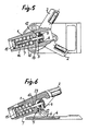
- FIGS. 7 and 8 show a variant of the embodiment described above. Moreover, the general design of this stop is the same as before. Consequently, the members which correspond to those of the previous embodiment are indicated, in FIGS. 7 and 8, by the same reference numbers assigned to the index "a".
- This stop differs from the previous one essentially by the fact that the plug 15 for adjusting the initial compression of the spring being eliminated, this adjustment is carried out by screwing the front end of the corresponding rod 10a into a threaded sleeve 14a carried by the cam 9a which is applied against the front flat 6a of the fixed plate 3a. Consequently, the front end of the rod 10a carries an operating head 24 accessible from the outside and which allows this rod to be screwed into the sleeve 14a to more or less compress the corresponding spring 7a.
- the vertical plate 3a serving as a support for the assembly comprises a base 25 of larger cross section which is riveted on the mounting plate 4a of the assembly.
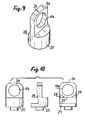
- FIGS. 9 and 10 The particular structure of the corresponding part appears in FIGS. 9 and 10.
- the front face of the vertical plate 3a is arranged to form a cam having a different effect according to the orientation. movement of the movable jaw.
- the upper edge 26 of this face is wider than its lower edge 27, on either side of which inclined facets 28 are provided.
- the present front stop can be the subject of many other modifications and variants.
- the body 1 or 1 a of the retaining jaw being made of metal, it is possible to manufacture it from plastics material by providing, in the bottom of the cavity 22, a metal plate to constitute the cam 8 support against the front flat 5.
Landscapes
- Footwear And Its Accessory, Manufacturing Method And Apparatuses (AREA)
- Organic Low-Molecular-Weight Compounds And Preparation Thereof (AREA)
- Materials Applied To Surfaces To Minimize Adherence Of Mist Or Water (AREA)
- Transition And Organic Metals Composition Catalysts For Addition Polymerization (AREA)
- Graft Or Block Polymers (AREA)
- Compositions Of Macromolecular Compounds (AREA)
- Motorcycle And Bicycle Frame (AREA)
- Chair Legs, Seat Parts, And Backrests (AREA)
Priority Applications (1)
| Application Number | Priority Date | Filing Date | Title |
|---|---|---|---|
| AT87400734T ATE46272T1 (de) | 1986-04-08 | 1987-04-03 | Sicherheitsskibindung. |
Applications Claiming Priority (2)
| Application Number | Priority Date | Filing Date | Title |
|---|---|---|---|
| FR8604970A FR2596664B1 (fr) | 1986-04-08 | 1986-04-08 | Fixation de securite pour ski |
| FR8604970 | 1986-04-08 |
Publications (2)
| Publication Number | Publication Date |
|---|---|
| EP0241360A1 EP0241360A1 (fr) | 1987-10-14 |
| EP0241360B1 true EP0241360B1 (fr) | 1989-09-13 |
Family
ID=9333993
Family Applications (1)
| Application Number | Title | Priority Date | Filing Date |
|---|---|---|---|
| EP87400734A Expired EP0241360B1 (fr) | 1986-04-08 | 1987-04-03 | Fixation de sécurité pour ski |
Country Status (6)
| Country | Link |
|---|---|
| US (1) | US4765641A (ja) |
| EP (1) | EP0241360B1 (ja) |
| JP (1) | JP2761639B2 (ja) |
| AT (1) | ATE46272T1 (ja) |
| DE (1) | DE3760544D1 (ja) |
| FR (1) | FR2596664B1 (ja) |
Families Citing this family (15)
| Publication number | Priority date | Publication date | Assignee | Title |
|---|---|---|---|---|
| FR2652273B2 (fr) * | 1986-04-08 | 1992-07-17 | Look Sa | Fixation de securite pour ski. |
| FR2633191B1 (fr) * | 1988-06-24 | 1992-10-02 | Salomon Sa | Fixation de securite pour ski |
| DE58906238D1 (de) * | 1988-07-28 | 1994-01-05 | Geze Sport | Seitenauslösbarer Vorderbacken einer Sicherheitsskibindung. |
| EP0408855B1 (de) * | 1989-07-21 | 1994-01-19 | HTM Sport- und Freizeitgeräte Aktiengesellschaft | Vorderbacken |
| DE9102427U1 (ja) * | 1991-02-28 | 1992-04-02 | Marker Deutschland Gmbh, 8116 Eschenlohe, De | |
| FR2689774B1 (fr) * | 1992-04-10 | 1994-06-10 | Salomon Sa | Sous-ensemble pour le rappel elastique de l'organe de retenue d'un element de fixation alpine. |
| US5671942A (en) * | 1994-02-23 | 1997-09-30 | Marker Deutschland Gmbh | Front jaw for a ski binding |
| AT403889B (de) * | 1995-10-19 | 1998-06-25 | Weigl Erwin Ing | Halterung für eine skibindung |
| FR2741816B1 (fr) * | 1995-12-04 | 1998-02-13 | Salomon Sa | Element de retenue de l'avant d'une chaussure sur une planche de glisse, notamment un ski |
| DE69815558T2 (de) | 1997-01-29 | 2004-04-29 | Look Fixations S.A. | Sicherheitsbindung an der Oberseite des Skistiefels |
| CH693129A5 (de) | 1998-11-16 | 2003-03-14 | Look Fixations Sa | Sicherheitsskibindung. |
| FR2808453B1 (fr) * | 2000-05-04 | 2002-08-02 | Salomon Sa | Element de retenue de l'avant d'une chaussure sur un ski |
| US8579317B2 (en) | 2011-09-19 | 2013-11-12 | Salomon S.A.S. | Binding for a boot on a gliding board |
| DE102013201727A1 (de) * | 2013-02-01 | 2014-08-07 | Marker Deutschland Gmbh | Fersenhalter mit rollenförmigem Sohlenhalter |
| FR3107652B1 (fr) | 2020-02-27 | 2022-01-28 | Salomon Sas | Butée avant de fixation pour planche de glisse |
Family Cites Families (14)
| Publication number | Priority date | Publication date | Assignee | Title |
|---|---|---|---|---|
| US2062862A (en) * | 1935-02-16 | 1936-12-01 | Micro Westco Inc | Guide for blade frames of slicing machines |
| DE1923038C3 (de) * | 1969-05-06 | 1975-01-16 | Karl Dieter 8000 Muenchen Forcht | Auslöse v.orderbacken |
| DE2448769C2 (de) * | 1974-10-12 | 1982-08-26 | Geze Gmbh, 7250 Leonberg | Haltevorrichtung für Sicherheitsskibindungen |
| FR2314742A1 (fr) * | 1975-06-20 | 1977-01-14 | Salomon & Fils F | Fixation de securite pour ski a compensation automatique des contraintes parasites |
| AT347308B (de) * | 1975-12-12 | 1978-12-27 | Smolka & Co Wiener Metall | Vorderbacken |
| FR2395046A1 (fr) * | 1977-06-22 | 1979-01-19 | Bonfils Juy Patrick | Dispositif de butee avant de securite pour ski |
| GB2004956A (en) * | 1977-09-26 | 1979-04-11 | Spica Spa | Clearance takeup floating bush |
| FR2439601A1 (fr) * | 1978-10-27 | 1980-05-23 | Look Sa | Fixation de securite pour ski |
| FR2458299A1 (fr) * | 1979-06-06 | 1981-01-02 | Salomon & Fils F | Fixation de securite pour ski |
| FR2478476A1 (fr) * | 1980-03-21 | 1981-09-25 | Salomon & Fils F | Fixation de securite pour ski |
| FR2533833A1 (fr) * | 1982-10-04 | 1984-04-06 | Salomon & Fils F | Fixation de securite pour ski |
| AT376895B (de) * | 1982-12-16 | 1985-01-10 | Tyrolia Freizeitgeraete | Ausloeseskibindung |
| FR2540735A1 (fr) * | 1983-02-14 | 1984-08-17 | Salomon & Fils F | Fixation de securite pour ski |
| US4682786A (en) * | 1984-10-04 | 1987-07-28 | Ste Look, French Societe Anonyme | Safety ski binding |
-
1986
- 1986-04-08 FR FR8604970A patent/FR2596664B1/fr not_active Expired
-
1987
- 1987-04-03 DE DE8787400734T patent/DE3760544D1/de not_active Expired
- 1987-04-03 EP EP87400734A patent/EP0241360B1/fr not_active Expired
- 1987-04-03 AT AT87400734T patent/ATE46272T1/de not_active IP Right Cessation
- 1987-04-06 US US07/034,921 patent/US4765641A/en not_active Expired - Lifetime
- 1987-04-08 JP JP62086729A patent/JP2761639B2/ja not_active Expired - Lifetime
Also Published As
| Publication number | Publication date |
|---|---|
| JP2761639B2 (ja) | 1998-06-04 |
| DE3760544D1 (en) | 1989-10-19 |
| EP0241360A1 (fr) | 1987-10-14 |
| JPS62243573A (ja) | 1987-10-24 |
| US4765641A (en) | 1988-08-23 |
| FR2596664A1 (fr) | 1987-10-09 |
| FR2596664B1 (fr) | 1988-12-23 |
| ATE46272T1 (de) | 1989-09-15 |
Similar Documents
| Publication | Publication Date | Title |
|---|---|---|
| EP0241360B1 (fr) | Fixation de sécurité pour ski | |
| EP1440713A1 (fr) | Fixation a energie deportee | |
| EP0025747B1 (fr) | Butée avant de fixation de ski | |
| EP0030175B1 (fr) | Butée avant de fixation de ski | |
| FR2654636A1 (en) | Multipurpose device for mounting a boot on a ski | |
| FR2465498A1 (fr) | Element formant machoire avant ou arriere pour une fixation de ski | |
| CH673229A5 (ja) | ||
| CH662953A5 (fr) | Fixation de securite pour ski. | |
| CH673400A5 (ja) | ||
| FR2511258A1 (fr) | Talonniere pour fixation de ski de securite | |
| FR2467612A1 (fr) | Frein de ski | |
| EP0179692A1 (fr) | Fixation de sécurité pour ski | |
| CH652936A5 (fr) | Fixation de securite pour ski. | |
| FR2499863A1 (fr) | Talonniere pour fixation de ski de securite | |
| CH673776A5 (ja) | ||
| CH642269A5 (fr) | Frein a ski. | |
| FR2725046A1 (fr) | Charniere elastique pour monture de lunettes | |
| FR2643276A1 (fr) | Dispositif d'appui, sur un ski, de la partie anterieure de la semelle d'une chaussure | |
| FR2652273A2 (fr) | Fixation de securite pour ski. | |
| CH619144A5 (ja) | ||
| EP0627947B1 (fr) | Dispositif d'appui d'une chaussure sur un ski, associe a une butee-avant de securite | |
| FR2495479A1 (fr) | Dispositif de reglage de la position longitudinale d'une fixation de securite pour ski | |
| EP0856337B1 (fr) | Fixation de sécurité à prise sur tige | |
| FR2598933A1 (fr) | Fixation de securite d'une chaussure sur un ski | |
| CH658998A5 (fr) | Frein de ski. |
Legal Events
| Date | Code | Title | Description |
|---|---|---|---|
| PUAI | Public reference made under article 153(3) epc to a published international application that has entered the european phase |
Free format text: ORIGINAL CODE: 0009012 |
|
| AK | Designated contracting states |
Kind code of ref document: A1 Designated state(s): AT CH DE LI |
|
| 17P | Request for examination filed |
Effective date: 19880114 |
|
| 17Q | First examination report despatched |
Effective date: 19890222 |
|
| GRAA | (expected) grant |
Free format text: ORIGINAL CODE: 0009210 |
|
| AK | Designated contracting states |
Kind code of ref document: B1 Designated state(s): AT CH DE LI |
|
| REF | Corresponds to: |
Ref document number: 46272 Country of ref document: AT Date of ref document: 19890915 Kind code of ref document: T |
|
| REF | Corresponds to: |
Ref document number: 3760544 Country of ref document: DE Date of ref document: 19891019 |
|
| PLBE | No opposition filed within time limit |
Free format text: ORIGINAL CODE: 0009261 |
|
| STAA | Information on the status of an ep patent application or granted ep patent |
Free format text: STATUS: NO OPPOSITION FILED WITHIN TIME LIMIT |
|
| 26N | No opposition filed | ||
| PGFP | Annual fee paid to national office [announced via postgrant information from national office to epo] |
Ref country code: CH Payment date: 19970501 Year of fee payment: 11 |
|
| PG25 | Lapsed in a contracting state [announced via postgrant information from national office to epo] |
Ref country code: LI Free format text: LAPSE BECAUSE OF NON-PAYMENT OF DUE FEES Effective date: 19980430 Ref country code: CH Free format text: LAPSE BECAUSE OF NON-PAYMENT OF DUE FEES Effective date: 19980430 |
|
| REG | Reference to a national code |
Ref country code: CH Ref legal event code: PL |
|
| PGFP | Annual fee paid to national office [announced via postgrant information from national office to epo] |
Ref country code: AT Payment date: 20020419 Year of fee payment: 16 |
|
| PGFP | Annual fee paid to national office [announced via postgrant information from national office to epo] |
Ref country code: DE Payment date: 20020515 Year of fee payment: 16 |
|
| PG25 | Lapsed in a contracting state [announced via postgrant information from national office to epo] |
Ref country code: AT Free format text: LAPSE BECAUSE OF NON-PAYMENT OF DUE FEES Effective date: 20030403 |
|
| PG25 | Lapsed in a contracting state [announced via postgrant information from national office to epo] |
Ref country code: DE Free format text: LAPSE BECAUSE OF NON-PAYMENT OF DUE FEES Effective date: 20031101 |