EP0241166B1 - Katalytischer Reaktionsapparat - Google Patents
Katalytischer Reaktionsapparat Download PDFInfo
- Publication number
- EP0241166B1 EP0241166B1 EP87302332A EP87302332A EP0241166B1 EP 0241166 B1 EP0241166 B1 EP 0241166B1 EP 87302332 A EP87302332 A EP 87302332A EP 87302332 A EP87302332 A EP 87302332A EP 0241166 B1 EP0241166 B1 EP 0241166B1
- Authority
- EP
- European Patent Office
- Prior art keywords
- burner
- chamber
- radiant
- wall
- skin
- Prior art date
- Legal status (The legal status is an assumption and is not a legal conclusion. Google has not performed a legal analysis and makes no representation as to the accuracy of the status listed.)
- Expired - Lifetime
Links
Images

Classifications
-
- B—PERFORMING OPERATIONS; TRANSPORTING
- B01—PHYSICAL OR CHEMICAL PROCESSES OR APPARATUS IN GENERAL
- B01J—CHEMICAL OR PHYSICAL PROCESSES, e.g. CATALYSIS OR COLLOID CHEMISTRY; THEIR RELEVANT APPARATUS
- B01J8/00—Chemical or physical processes in general, conducted in the presence of fluids and solid particles; Apparatus for such processes
- B01J8/02—Chemical or physical processes in general, conducted in the presence of fluids and solid particles; Apparatus for such processes with stationary particles, e.g. in fixed beds
- B01J8/06—Chemical or physical processes in general, conducted in the presence of fluids and solid particles; Apparatus for such processes with stationary particles, e.g. in fixed beds in tube reactors; the solid particles being arranged in tubes
- B01J8/062—Chemical or physical processes in general, conducted in the presence of fluids and solid particles; Apparatus for such processes with stationary particles, e.g. in fixed beds in tube reactors; the solid particles being arranged in tubes being installed in a furnace
-
- C—CHEMISTRY; METALLURGY
- C01—INORGANIC CHEMISTRY
- C01B—NON-METALLIC ELEMENTS; COMPOUNDS THEREOF; METALLOIDS OR COMPOUNDS THEREOF NOT COVERED BY SUBCLASS C01C
- C01B3/00—Hydrogen; Gaseous mixtures containing hydrogen; Separation of hydrogen from mixtures containing it; Purification of hydrogen; Reversible storage of hydrogen
- C01B3/02—Production of hydrogen; Production of gaseous mixtures containing hydrogen
- C01B3/32—Production of hydrogen; Production of gaseous mixtures containing hydrogen by reaction of gaseous or liquid organic compounds with gasifying agents, e.g. water, carbon dioxide or air
- C01B3/323—Catalytic reaction of gaseous or liquid organic compounds other than hydrocarbons with gasifying agents
-
- C—CHEMISTRY; METALLURGY
- C01—INORGANIC CHEMISTRY
- C01B—NON-METALLIC ELEMENTS; COMPOUNDS THEREOF; METALLOIDS OR COMPOUNDS THEREOF NOT COVERED BY SUBCLASS C01C
- C01B3/00—Hydrogen; Gaseous mixtures containing hydrogen; Separation of hydrogen from mixtures containing it; Purification of hydrogen; Reversible storage of hydrogen
- C01B3/02—Production of hydrogen; Production of gaseous mixtures containing hydrogen
- C01B3/32—Production of hydrogen; Production of gaseous mixtures containing hydrogen by reaction of gaseous or liquid organic compounds with gasifying agents, e.g. water, carbon dioxide or air
- C01B3/34—Production of hydrogen; Production of gaseous mixtures containing hydrogen by reaction of gaseous or liquid organic compounds with gasifying agents, e.g. water, carbon dioxide or air by reaction of hydrocarbons with gasifying agents
- C01B3/38—Production of hydrogen; Production of gaseous mixtures containing hydrogen by reaction of gaseous or liquid organic compounds with gasifying agents, e.g. water, carbon dioxide or air by reaction of hydrocarbons with gasifying agents using catalysts
- C01B3/384—Production of hydrogen; Production of gaseous mixtures containing hydrogen by reaction of gaseous or liquid organic compounds with gasifying agents, e.g. water, carbon dioxide or air by reaction of hydrocarbons with gasifying agents using catalysts with external heating of the catalyst
-
- F—MECHANICAL ENGINEERING; LIGHTING; HEATING; WEAPONS; BLASTING
- F23—COMBUSTION APPARATUS; COMBUSTION PROCESSES
- F23D—BURNERS
- F23D14/00—Burners for combustion of a gas, e.g. of a gas stored under pressure as a liquid
- F23D14/12—Radiant burners
- F23D14/16—Radiant burners using permeable blocks
-
- C—CHEMISTRY; METALLURGY
- C01—INORGANIC CHEMISTRY
- C01B—NON-METALLIC ELEMENTS; COMPOUNDS THEREOF; METALLOIDS OR COMPOUNDS THEREOF NOT COVERED BY SUBCLASS C01C
- C01B2203/00—Integrated processes for the production of hydrogen or synthesis gas
- C01B2203/02—Processes for making hydrogen or synthesis gas
- C01B2203/0205—Processes for making hydrogen or synthesis gas containing a reforming step
- C01B2203/0227—Processes for making hydrogen or synthesis gas containing a reforming step containing a catalytic reforming step
- C01B2203/0233—Processes for making hydrogen or synthesis gas containing a reforming step containing a catalytic reforming step the reforming step being a steam reforming step
-
- C—CHEMISTRY; METALLURGY
- C01—INORGANIC CHEMISTRY
- C01B—NON-METALLIC ELEMENTS; COMPOUNDS THEREOF; METALLOIDS OR COMPOUNDS THEREOF NOT COVERED BY SUBCLASS C01C
- C01B2203/00—Integrated processes for the production of hydrogen or synthesis gas
- C01B2203/08—Methods of heating or cooling
- C01B2203/0805—Methods of heating the process for making hydrogen or synthesis gas
- C01B2203/0811—Methods of heating the process for making hydrogen or synthesis gas by combustion of fuel
-
- C—CHEMISTRY; METALLURGY
- C01—INORGANIC CHEMISTRY
- C01B—NON-METALLIC ELEMENTS; COMPOUNDS THEREOF; METALLOIDS OR COMPOUNDS THEREOF NOT COVERED BY SUBCLASS C01C
- C01B2203/00—Integrated processes for the production of hydrogen or synthesis gas
- C01B2203/10—Catalysts for performing the hydrogen forming reactions
- C01B2203/1005—Arrangement or shape of catalyst
- C01B2203/1011—Packed bed of catalytic structures, e.g. particles, packing elements
- C01B2203/1017—Packed bed of catalytic structures, e.g. particles, packing elements characterised by the form of the structure
-
- C—CHEMISTRY; METALLURGY
- C01—INORGANIC CHEMISTRY
- C01B—NON-METALLIC ELEMENTS; COMPOUNDS THEREOF; METALLOIDS OR COMPOUNDS THEREOF NOT COVERED BY SUBCLASS C01C
- C01B2203/00—Integrated processes for the production of hydrogen or synthesis gas
- C01B2203/12—Feeding the process for making hydrogen or synthesis gas
- C01B2203/1205—Composition of the feed
- C01B2203/1211—Organic compounds or organic mixtures used in the process for making hydrogen or synthesis gas
- C01B2203/1217—Alcohols
- C01B2203/1223—Methanol
-
- Y—GENERAL TAGGING OF NEW TECHNOLOGICAL DEVELOPMENTS; GENERAL TAGGING OF CROSS-SECTIONAL TECHNOLOGIES SPANNING OVER SEVERAL SECTIONS OF THE IPC; TECHNICAL SUBJECTS COVERED BY FORMER USPC CROSS-REFERENCE ART COLLECTIONS [XRACs] AND DIGESTS
- Y02—TECHNOLOGIES OR APPLICATIONS FOR MITIGATION OR ADAPTATION AGAINST CLIMATE CHANGE
- Y02P—CLIMATE CHANGE MITIGATION TECHNOLOGIES IN THE PRODUCTION OR PROCESSING OF GOODS
- Y02P20/00—Technologies relating to chemical industry
- Y02P20/10—Process efficiency
- Y02P20/129—Energy recovery, e.g. by cogeneration, H2recovery or pressure recovery turbines
Definitions
- This invention relates to catalytic reaction apparatus such as for producing product gases from a feedstock.
- Catalytic reaction apparatus such as for converting hydrocarbon feedstocks to useful industrial gases, for example hydrogen
- Catalytic reaction apparatus such as for converting hydrocarbon feedstocks to useful industrial gases, for example hydrogen
- commercial production of hydrogen from hydrocarbon feedstocks is most commonly achieved by passing a mixture of steam and hydrocarbon through catalyst filled reactor tubes vertically supported within a furnace chamber.
- Portions of the reactor tube which are in direct line of sight with the burner flame, which are impinged by the burner flame, or which are too closely spaced to the radiating refractory, will become hotter than the remaining portions.
- U.S. Patent 4,098,587 to Kral et al there is described a compact reformer comprising a plurality of reactor tubes disposed within the combustion volume of a furnace.
- Baffles such as sleeves, are disposed around portions of the reactor tubes to shield the tubes from excessive radiant heat from the walls of the furnace and to more evenly distribute heat among and around all of the reactors. It is therein described that the use of such baffles allows close spacing between reactor tubes while simultaneously avoiding excessive local heating of reactor tube walls.
- uniform radiant heat distribution to the reactor tube walls is achieved through the use of an annular reaction chamber concentrically disposed around an internal burner chamber containing a uniformly radiating infrared burner. This configuration is in contradiction to the prior art U.S. Patent 4, 098,587 which teaches the use of reactor tubes disposed within a furnace volume and surrounded by baffles.
- catalytic reaction apparatus in which a catalyst bed is provided with a plurality of heating tubes.
- An air pipe is arranged concentrically within each heating tube.
- the air pipe is closed off at its upper end and includes a porous wall section spaced from the upper end of the pipe. Combustion takes place under the influence of a catalyst on the surface of the porous wall section.
- the catalyst reaction apparatus as embodied in the present invention achieves the objects of compact design and long life expectancy by application of a novel burner chamber configuration which prevents flame impingement or direct line-of-sight between burner flame and reaction chamber, and which provides a means for uniformly distributing heat along the axial and circumferential dimensions of the reactor. It is the general object of the present invention to provide a novel catalytic reaction apparatus for the production of industrial gases from a hydrocarbon or methanol feedstock which is simultaneously compact, has improved life expectancy, has rapid response, and is highly efficient.
- the subject invention is particularly well suited for small scale generation of industrial gases.
- a compact burner chamber employing an infrared burner assembly is configured to more uniformly distribute radiant energy along the axial and circumferential dimension of the reactionc chamber wall.
- Heat released by the combustion of fuel and oxidant is used to heat a ceramic surface centrally disposed within an annular reaction chamber.
- the heated ceramic surface serves to uniforml;y distribute radiant energy to the reaction chamber wall, thereby minimising local maldistribution of heat within the burner chamber and avoiding the problem of direct flame impingement on the reaction chamber wall.
- the infrared burner assembly comprises a porous ceramic fiber burner which permits the efflux of fuel and oxidant from the burner core to the outer surface of the ceramic fibre.
- the properties of the ceramic fibre serve to stabilise the combustion reaction in a shallow zone proximal to the outer surface of the ceramic fibre.
- the combustion reaction heats the ceramic fibre to incandescence permitting uniform radiation of energy to the reaction chamber.
- the infrared burner assembly comprises an indirectly fired, non-permeable, ceramic conduit.
- Fuel and oxidant are combusted in a diffusion flame disposed within the burner core. Radiation from the flame and hot burner gases heat the ceramic conduit to incandescence, thereby permitting uniform radiation to the reaction chamber.
- the lower portions of the burner chamber are typically configured to form a convective chamber for enhancing heat transfer from the burner gases to the lower portions of the reaction chamber.
- the reaction chamber which is substantially filled with a catalyst, is typically substantially concentrically disposed around the burner chamber, defining an annular passageway for the contact of reactant gases over the catalyst.
- a wall conduit is typically substantially concentrically disposed around the reaction chamber, defining an annular passageway therebetween for the flow of hot product gases exiting the reaction chamber.
- the hot product gases flow counter-currently against reactant gases, thereby releasing sensible heat to the endothermic reaction.
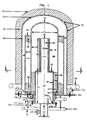
- the catalytic reaction apparatus 10 of Figures 1 and 2 depicts the preferred embodiment of the present invention.
- the apparatus comprises several primary chambers including a burner chamber 12, a reaction chamber 14, and a regeneratove heat transfer chamber 16.
- the burner chamber 12 is defined by the volume within or fully enclosed by the reaction chamber wall 18, the burner chamber upper end wall 19, the reactor base plate 38, and the burner assembly nozzle 36.
- An axially extending infrared burner assembly 20 is centrally disposed within the burner chamber 12.
- the infrared burner assembly may be considered to comprise an upper portion, hereinafter referred to as the radiant burner 22, and a lower portion hereinafter referred to as the burner stock 24.
- the burner chamber may also be considered to comprise an upper portion hereinafter referred to as the radiant chamber (i.e. sub-chamber) 26 and a lower portion hereinafter referred to as the convection chamber (i.e. sub-chamber) 28.
- the radiant chamber 26 comprises an annular passageway or zone defined by the volume enclosed by the reaction chamber upright wall 18 and the radiant burner upright skin or porous shell 30.
- the convection chamber 28 comprises an annular passageway or zone defined by the volume enclosed by the reaction chamber wall and the burner upright stock wall or shell 32.
- the latter typically is of large diameter than shell 30.
- the burner stock 24 may be secured at its base by means of welded attachment 32a to the burner assembly horizontal blind flange 34.
- the latter is secured to the burner chamber nozzle 36 by means of bolted attachment at 34a, permitting fee disengagement of the infrared burner assembly 20 from the burner chamber 12.
- the burner assembly nozzle 36 is typically secured to the reactor base plate 38 means of welded attachment at 36.
- the axially extending, vertically disposed radiant burner 22 is supported at its base by annular top wall 35 of the burner stock 24.
- the radiant burner 22 is comprised of a gas permeable internal structure 29 fully surrounded or enclosed by a layer of porous ceramic fibre hereinafter referred to as the radiant burner skin 30.
- the gas permeable internal structure 29 typically comprises a metallic screen or wire mesh.
- the empty volume enclosed by the gas permeable internal structure 29 is hereinafter referred to as the radiant burner core 40, and which extends the length of the internal structure 29, and fills the space surrounded by the internal structure.
- burner air is introduced to the burner assembly through a burner air inlet nozzle 42 attached to the burner assembly blind flange 34.
- Burner fuel is introduced into the burner assembly through a burner fuel nozzle 44 attached to the burner air nozzle 42, to mix with air in zone 41.
- Premixed burner air and burner fuel upwardly enters the burner stock chamber 46 and thereupon passes into the radiant burner core 40.
- the air and fuel mixture effuses laterally through the radiant burner skin 30, whereupon the combustion reaction occurs in a shallow zone proximal to the outer surface of the skin.
- the combustion reaction heats the radiant burner skin 30 to incandescense, thereby providing a means of uniform or substantially uniform radiant heat transfer laterally to the reaction chamber upright wall 18, and generally throughout the vertical length of the skin.
- the burner upper end plate 45 is constructed from non-gas permeable material to prevent excessive radiation to the burner chamber end cap 19.
- the unit radial pressure drop through the radiant burner skin 30 is considerably greater than the unit axial pressure drop through the burner core 40, thereby ensuring an even distribution of gaseous air and fuel mix supply across the axial dimension of the radiant burner 22, and about the circumferential extent of same.
- the combustion reaction is stabilised within the radiant burner skin 30 due to the back-conduction of heat released on the skin outer surface. Flashback is prevented by the counteracting effect of heat removal from inner surface of the radiant burner skin 30 due to the convective flow of the inflowing air and fuel mixture.
- Burner gases effusing through the radiant burner skin 30 thereupon flow downwardly as exhaust gases via the open radiant chamber 26 to the convection chamber 28.
- the annular passageway of the convection chamber 28 is substantially filled with a heat transfer packing material 48 configured to increase the effectiveness of convective heat transfer from the burner gases to the lower portions of the reactor chamber wall 18.
- the heat transfer packing material 48 is supported at the bottom of the convection chamber 28 by means of an annular screen 47.
- Typical heat transfer packing materials include metallic mesh, and ceramic spheres, rods, or rings as are employed in the industry Burner exhaust gases exiting the lower portion of the convection chamber 28 are collected at the gas exit 49 by means of a circumferential series of burner gas outlet conduits 50 extending through and protruding from the reactor base plate 38.
- the outlet conduits 50 are disposed radially and circumferentially to correspond with the union of the annular passageway of the convection chamber 28 and the reactor base plate 38. A sufficient number of conduits 50 are employed to ensure uniform distribution of the burner gases within the convection chamber 28. Conduits 50 are individually extended from the reactor base plate 38 to connect with manifold 52 circumferentially disposed below the reactor base plate, thereby providing a substantial conduit for the flow of gases from the catalytic reaction apparatus 10.
- the burner chamber provides a means for efficiently supplying endothermic heat reaction to the reaction chamber wall 18.
- the compactly disposed upright radiant burner 22 provides a uniform and substantial source of radiant heat energy for wall 18, while avoiding the problems of flame impingement and local heat maldistribution common among conventional flame burners.
- the convection chamber 28 provides a means for enhanced heat recovery, thereby maximising the thermal efficiency of the catalytic reaction apparatus 10.
- the centrally disposed burner assembly provides a means for substantially isolating the hot burner hases from the environment thereby minimising undesirable system heat losses which become increasingly significant for compact apparatus with large surface to volume ratios.
- reaction chamber outer wall 54 An axially extending wall conduit, hereinafter referred to as the reaction chamber outer wall 54,is concentrically disposed around the reaction chamber inner wall 18, thereby defining an annular volume or zone 14 therebetween referred to as the reaction chamber 14.
- Inner wall 18 and outer wall 54 are individually secured to the reactor base plate 38 by means of welded attachment.
- chamber 14 is substantially filled with steam reforming catalyst pellets 56 which are supported on a screen 58 disposed at the inlet end 60 of the reaction chamber. To prevent fluidisation of the steam reforming catalyst pellets 56 due to the up-flow of reactants, the catalyst is contained at the reaction chamber outlet means of a containment screen 62.
- the reaction chamber outlet is in gas communication with the regenerative heat transfer chamber inlet 63, thereby permitting the up-flow of hot product gases from the reaction chamber 14 to he regenerative heat transfer chamber 16, wherein the product gases flow downwardly.
- the upper portion of the reaction chamber outer wall 54 may be partially extended over the burner chamber end cap 19 thereby directing a flow of product gases over the burner chamber end cap 19 to provide convective cooling and to minimise the formation of quiescent zones thereabove.
- the feed reactant mixture supplied at 100 enters the reactant gas manifold 64, whereupon the reactant mixture is uniformly distributed to the reaction chamber inlet 60 by means of a series of reactant gas inlet conduits 66 terminating at and through the reactor base plate 38, and disposed radially and circumferentially to correspond with the union of the annular passageway of the reactant chamber 14 and the reactor base plate.
- An axially extending wall conduit hereinafter referred to as the regenerative heat transfer chamber outer wall 68, is concentrically disposed around the reaction chamber outer wall 54 thereby defining an annular volume or zone therebetween referred to as the regenerative heat transfer chamber 16.
- the chamber 16 is enclosed at its upper end by a reactor end cap 70 and its lower end by joindure or intersection at 101 with the reactor base plate 38.
- Wall 68 is typically secured to the reactor base plate by means of a bolted attachment.
- the wall 68 and the reactor cap 70 may be considered to form the outer shell 72 of the catalytic reaction apparatus 10. So arranged, the shell 72 may be freely axially disengaged and removed from the remainder of the catalytic reactor apparatus permitting inspection, removal and replacement of the steam reforming catalyst pellets 56 and other reactor internals.
- the regenerative heat transfer chamber 16 being in gas communication with the reaction cahmber 14 receives hot product gases at its upper portion.
- the hot product gases flow downward through the regenerative heat transfer chamber 16 releasing sensible heat to the reaction chamber outer wall 54 thereby providing endothermic reaction heat to the counter current flowing reactant mixture within the reaction chamber 14.
- the product gas outlet conduits 74 extends to the product gas manifold 76 Circumferentially disposed around the regenerative heat transfer chamber outer wall.
- the reactor outer shell 72 is substantially isolated from the ambient environment by means of an insulating layer 78 thereby minimising heat losses from the reactor.
- the reactor base plate 38, the burner gas manifold 52, the product gas manifold 76, the reactant gas manifold 64, and other hot surfaces may be similarly heat insulated.
- a gaseous mixture of steam and a reformable feedstock enters the reactant mixture manifold 64, whereupon the gas is uniformly distributed to the reaction chamber inlet 14 through a series of reactant gas inlet conduits 66.
- the gas mixture flows upward through the annular volume of the reaction chamber, reacting in the presence of the steam reforming catalyst pellets 56 to produce hydrogen, carbon monoxide and other product gases.
- endothermic reaction heat is supplied primarily by means of convective heat transfer from the burner gases flowing countercurrently through the convection chamber 28.
- endothermic heat is supplied primarily by radiative heat transfer from the radiant burner skin 30 to the reaction chamber inner wall 18. Additional heat is supplied to the reactant gas mixture by convective heat transfer from the hot product gases flowing countercurrently through the regenerative heat transfer chamber 16.
- the reactant gas mixture travels upward within the reaction chamber 14, it continues to react and absorb heat, reaching a maximum temperature and conversion level at the reaction chamber outlet.
- the hot product gases enters the regenerative heat transfer chamber inlet 63 and thereupon traverses the length of the annular volume transferring heat therefrom back into the reaction chamber 14.
- the fuel and air mixture flows through the burner stock 46 and into the burner core 40 thereupon effusing through the radiant burner skin 30. Combustion of the fuel and air mixture occurs in a shallow zone proximal to the outer layer of the radiant burner skin 30 thereby heating its surface and providing a uniform, radiant source for transferring heat to the reaction chamber inner wall 18.
- Burner gases entering the radiant chamber 26 from the radiant burner skin 30 flows downward through the convection chamber 28 thereby providing additional reaction heat to the lower portions of the reaction chamber inner wall.
- the present invention permits a particularly compact arrangement for the burner chamber 12, reactor chamber 14, and the regenerative heat transfer chamber 16.
- the burner chamber is configured to provide a uniform distribution of heat to the reaction chamber wall 18.
- the present invention eliminates the problems of flame impingement and local heat maldistribution common among compact flame burner arrangements thereby providing extended life expectancy and improved performance for the catalytic reaction apparatus. Since the heat capacity of the internal burner assembly 20 and burner chamber 12 is substantially less than that of a furnace box lined with thick refractory material, the present invention is adapted to provide an apparatus with a particularly rapid start-up and turndown response.
- the combination of radiant and convective heat transfer in the burner chamber 12 coupled with additional heat recovery in the regenerative heat transfer chamber 16 is also adapted to provide for a high thermal efficiency.
- the catalytic reaction apparatus is designed with easily removably components for ease of maintenance and access to catalyst, burner, etc. Also, the apparatus is designed so that each primary wall means is free standing, self supporting, and fixed only at one end, thereby minimising thermal stress during the thermal expansion.
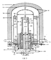
- FIG 3 depicts another embodiment of the present invention. Similar reference numerals represent components which are the same as those in Figure 1.
- the burner assembly 120 may be considered to comprise an upper portion hereinafter referred to as the radiant burner 122 and a lower portion hereinafter referred to as a burner stock 124.
- the radiant burner 122 is disposed in the upper portion of the burner chamber 12 hereinafter referred to as radiant chamber 26.
- the space between the lower portion of the reactor chamber inner wall 18 and the burner stock wall 132 defines an annular passageway hereinafter referred to as the convection chamber 29.
- an axially extending burner tip assembly 141 is centrally disposed within the burner stock chamber 146.
- the burner tip assembly comprises a cylindrical, burner fuel supply conduit 151. Concentrically disposed within a cylindrical burner air conduit 153.
- the burner tip assembly 141 is secured to the burner assembly blind flange 134 and includes inlet means 144 introducing burner fuel to the burner fuel supply conduit 151 and inlet means 142 for introducing burner air to the burner air supply conduit 153.
- the annular volume between the burner stock wall 132 and the burner air supply conduit 153 is substantially filled with insulating material 155. Combustion of burner air and burner fuel at the burner tip forms an attached diffusion flame directed vertically upward within the radiant burner core 140.
- the radiant burner 122 is comprised of an axially extending ceramic conduit, hereinafter referred to as the radiant skin 130, which is substantially non-permeable to gases and which is vertically disposed within the radiant chamber 26 and supported at its base by the burner stock 125.
- the volume enclosed by the radiant skin 130 defines the radiant burner core 140 through which flows hot burner gases.
- the radiant burner 122 includes outlet means 131 for hot burner gases exiting the upper portion of the radiant burner.
- the attached flame at the burner tip 157 and the resulting hot burner gases radiate energy to the radiant skin 130, thereby heating it to high temperatures.
- the heated radiant skin 130 thereupon uniformly re-radiates heat energy to the reaction chamber wall 18 thereby providing endothermic reaction heat to the reaction chamber 14.
- the convection chamber 28 is substantially filled with a packing material 48 for enhancing the effectiveness of convective heat transfer from the burner gases to the lower portion of the reaction chamber wall.
- the burner chamber provides a means for efficiently supplying endothermic heat to the reaction chamber 14.
- the ceramic radiant burner 120 serves to protect the reaction chamber wall 18 from direct view of the burner flame, and to more uniformly distribute the burner gas heat release within the axial and circumferential dimension of the radiant chamber 26, thereby minimising local hot spots on the reaction chamber wall 18 and thus extending life expectancy for the catalytic reaction apparatus 10.
Landscapes
- Chemical & Material Sciences (AREA)
- Chemical Kinetics & Catalysis (AREA)
- Engineering & Computer Science (AREA)
- Organic Chemistry (AREA)
- Combustion & Propulsion (AREA)
- Health & Medical Sciences (AREA)
- General Health & Medical Sciences (AREA)
- Inorganic Chemistry (AREA)
- Mechanical Engineering (AREA)
- General Engineering & Computer Science (AREA)
- Hydrogen, Water And Hydrids (AREA)
Claims (13)
- Katalytischer Reaktionsapparat, umfassend eine aufrechte Brennkammer (12) und darin eine aufrechte Infrarot-Brennereinrichtung (20), eine aufrechte innere Wand (18), die die Brennereinrichtung (20) umgibt und von dieser beabstandet ist, um von der Brennereinrichtung (20) Strahlungswärmeübertragung zu erhalten, und eine Einrichtung, die ein Katalysatorbett (56) einschließt und um die innere Wand (18) herum angeordnet ist, um eine Versorgung mit Einsatzgas aufzunehmen, welches erwärmt werden soll durch Übertragung von der Wand (18) zum Bett (56) zwecks Reaktion des Gases und anschließendem Durchfluß zum Ausgang aus dem Apparat, wobei ein Auslaß (50) für Brennerabgase derart angeordnet ist, daß das Abströmen der Abgase nach unten in den Raum zwischen der aufrechten Wand (18) und der Brennereinrichtung (20) erfolgt, um die innere Wand (18) konvektiv zu erwärmen,
dadurch gekennzeichnet,
daß die Brennerkammer (12) eine obere Teilkammer (26) und eine untere Teilkammer (28) einschließt und die Brennereinrichtung einen oberen Strahlungsbrennerteil (22) in der oberen Teilkammer (26) und in der unteren Teilkammer einen Brennerschaft (24) von anderer Konstruktion als der obere Strahlungsbrennerteil (22) einschließt, wobei der obere Strahlungsbrennerteil (22) eine aufrechte poröse Außenhaut aus Keramikfasern beinhaltet und ein gasdurchlässiger Kern von der Haut umgeben ist, und daß die Brennereinrichtung (20) einen oberen Auslaß aufweist. - Katalytischer Reaktionsapparat nach Anspruch 1, bei dem der gasdurchlässige Kern den von der Haut umgebenen Raum im wesentlichen ausfüllt und eine Höhe des vertikal-axialen Druckverlustes hat, die geringer ist als die Höhe des vertikal-axialen Druckverlustes der Haut, wobei eine gleichmäßige Verteilung der Zufuhr der Luft und des Brennstoffgemisches entlang der axialen Erstreckung der Haut sichergestellt wird und auch eine gleichmäßige Verbrennung nahe der Haut und ein anschließendes abwärtsgerichtetes Abströmen der Abgase in die untere Teilkammer (28) gesichert werden.
- Katalytischer Reaktionsapparat nach Anspruch 1 oder 2, bei dem die untere Teilkammer (28) eine Wärmeübertragungspackung (48) für die Wärmeübertragung zur aufrechten inneren Wand (18) enthält und Abgasauslässe (50) zum Ableiten der Abgase aus der Packung (48) zwecks Abfuhr aus dem Apparat vorhanden sind.
- Katalytischer Reaktionsapparat nach einem der Ansprüche 1 bis 3, bei dem die genannte Einrichtung eine äußere Wand (54), die die aufrechte innere Wand (18) umgibt und eine Zone zur Aufnahme des Katalysatorbetts (56) bildet, wobei die Zone einen unteren Eingang (60) für die Aufnahme des Einlasses des Einsatzgases aufweist, und einen äußeren Mantel (68) einschließt, der mit Abstand außerhalb der äußeren Wand (54) angeordnet ist und sich über die Wände (18, 54) und die Brennereinrichtung (20) erstreckt, wobei der äußere Mantel (68) relativ abnehmbar ist, um Zugang zu der Brennereinrichtung (20) und dem Katalysatorbett (56) zu verschaffen.
- Katalytischer Reaktionsapparat nach Anspruch 4, bei dem der äußere Mantel (68) beabstandet angeordnet ist von der aufrechten äußeren Wand (54), um eine regenerative Wärmeübertragungskammer, durch welche heiße Produktgase abwärts über die äußere Wand (54) strömen, und Auslaßmittel (74) für das heiße Produktgas zu bilden.
- Katalytischer Reaktionsapparat nach einem der Ansprüche 1 bis 5, bei dem das Katalysatorbett (56) aus einem Dampfreformierkatalysator besteht und Einlaßmittel (60) vorgesehen sind, die eine Mischung von Dampf und reformierbarem Kohlenwasserstoff-Einsatzmaterial zum Katalysator (56) führen zur Erzeugung von Wasserstoff und Kohlenmonoxid.
- Katalytischer Reaktionsapparat nach Anspruch 6, beinhaltend eine Basis (38), die die inneren und äußeren Wände (18, 54) trägt, damit diese frei stehen, wodurch eine freie vertikale Wandausdehnung und -schrumpfung möglich ist.
- Katalysatoreinrichtung nach einem der Ansprüche 1 bis 7, bei dem die Brennereinrichtung (20) eine sich axial erstreckende Keramikröhre (30) und Mittel einschließt zur Erzeugung der Flamme, die in die Röhre aufsteigt und diese erhitzt.
- Endothermer katalytischer Reaktionsapparat, umfassend eine sich axial erstreckende Reaktionskammer (14) und eine sich axial erstreckende regenerative Wärmeübertragungskammer (16), eine innen angeordnete, sich axial erstreckende Brennerkammer (12) für die Zufuhr von endothermer Reaktionswärme zur Reaktionskammer (14), welche beabstandet etwa konzentrisch um die Brennerkammer (12) herum angeordnet ist, wobei die Brennerkammer eine Infrarot-Brennereinrichtung (20) und eine dieser zugeordnete Brennerabgasleitungseinrichtung (50) enthält, wobei die Brennerkammer (12) begrenzt wird durch etwa zylindrische innere Wände (18) der Reaktionskammer (14) und wobei die axial sich erstreckende Reaktionskammer (14) durch die inneren Wände (18), die den Brennerabgasen in der Brennerkammer (12) ausgesetzt sind, und auch durch etwa konzentrische zylindrische äußere Wände (54) begrenzt wird, die den heißen Produktgasen in der regenerativen Wärmeübertragungskammer (16) ausgesetzt sind, und wobei ein erster Raum zwischen den inneren und äußeren Wänden (18, 54) der Reaktionskammer besteht, der eine etwa ringförmige Kammer definiert, welche im wesentlichen gefüllt ist mit einem Katalysator und welche auch einen Durchlaß darstellt für das Leiten von Reaktionsgasen über den Katalysator, und wobei die sich axial erstreckende regenerative Wärmeübertragungskammer (16) beabstandet in einer etwa konzentrischen Anordnung um die Reaktionskammer herum angeordnet ist und begrenzt ist durch die äußeren Wände (54) der Reaktionskammer (14) und durch eine etwa konzentrische zylindrische äußere Ummantelung (68, 70) des katalytischen Reaktionsapparates, und wobei ein zweiter Raum zwischen den äußeren Wänden (54) und der äußeren Ummantelung (68, 70) einen etwa ringförmigen Durchlaß für den Durchfluß von heißen Prozeßgasen definiert,
dadurch gekennzeichnet,
daß die Brennerkammer (12) eine obere Strahlungskammer (26) und eine untere Konvektionskammer (28) beinhaltet und die Infrarot-Brennereinrichtung (20) einen oberen Strahlungsbrennerteil (22) und einen unteren Brennerschaftteil (24) von andersartiger Konstruktion als die des oberen Strahlungsbrennerteils (22) umfaßt, wobei der Strahlungsbrennerteil (22) vertikal im Abstand innerhalb der oberen Strahlungskammer (26) der Brennerkammer (12) angeordnet ist und der Brennerschaftteil (24) die innere Wand der unteren Konvektionskammer (28) bildet, und wobei der Strahlungsbrennerteil (22) eine gasdurchlässige Stützstruktur aufweist, die ein inneres Volumen besitzt, das einen Brennerkern definiert, wobei die Stützstruktur ein Keramikfasermaterial einschließt, das eine Strahlungshaut (30) bildet, welche einen wesentlichen Teil der Stützstruktur einschließt. - Katalytischer Reaktionsapparat nach Anspruch 1, bei dem der Strahlungsbrennerteil (122) eine zylindrische undurchlässige keramische Brennergasröhre (130) umfaßt, die eine Strahlungshaut mit einem inneren Volumen bildet, welches einen Brennerkern definiert, wobei der Brennerkern heiße Brennergase aus der Verbrennung an einer Brennerspitze (157) erhält, die mit Abstand innerhalb des Brennerkerns angeordnet ist, und wobei der Strahlungsbrennerteil (122) Auslaßeinrichtungen (131) für Brennergase aufweist, die zur Strahlungskammer austreten.
- Reaktionsapparat nach Anspruch 9, bei dem die Strahlungshaut (30) so gestaltet ist, daß ein Ausströmen von Brennstoff und Oxidationsmittel vom Brennerkern zur Strahlungskammer möglich ist, wodurch eine stabile Verbrennungsreaktion in einer flachen Schicht nahe der äußeren Oberfläche der Strahlungshaut (30) erzielt wird und wobei die Verbrennungsreaktion die Strahlungshaut bis zum Glühen erwärmt, wodurch eine Quelle von gleichmäßiger Strahlungswärme für die innere Wand (18) der Reaktionskammer (14) erhalten wird.
- Reaktionsapparat nach Anspruch 9 oder 10, bei dem die Strahlungshaut (30) im wesentlichen gleichmäßig beabstandet ist von der inneren Wand (18) der Reaktionskammer, um einen ringförmigen Brennergasdurchlaß der Strahlungszone dazwischen zu definieren, wobei die Strahlungszone (26) in Gasverbindung mit der unteren Konvektionskammer (28) steht.
- Reaktionsapparat nach einem der Ansprüche 9 bis 12, beinhaltend eine Brennkammerdüseneinrichtung (36), welche mit der Infrarot-Brennereinrichtung (20) durch Schraubflanschverbindung verbunden ist, wodurch ein Abbau der Infrarot-Brennereinrichtung (20) von der Strahlungskammer (12) möglich ist, wobei die Infrarot-Brennereinrichtung (20) auch Einlaßmittel (44) für die Einleitung von Brennstoff und Oxidationsmittel in einen Kern, welcher innerhalb der Brennereinheit definiert ist, einschließt.
Applications Claiming Priority (2)
| Application Number | Priority Date | Filing Date | Title |
|---|---|---|---|
| US06/842,830 US4692306A (en) | 1986-03-24 | 1986-03-24 | Catalytic reaction apparatus |
| US842830 | 1986-03-24 |
Publications (3)
| Publication Number | Publication Date |
|---|---|
| EP0241166A2 EP0241166A2 (de) | 1987-10-14 |
| EP0241166A3 EP0241166A3 (en) | 1988-07-20 |
| EP0241166B1 true EP0241166B1 (de) | 1992-05-27 |
Family
ID=25288344
Family Applications (1)
| Application Number | Title | Priority Date | Filing Date |
|---|---|---|---|
| EP87302332A Expired - Lifetime EP0241166B1 (de) | 1986-03-24 | 1987-03-18 | Katalytischer Reaktionsapparat |
Country Status (3)
| Country | Link |
|---|---|
| US (1) | US4692306A (de) |
| EP (1) | EP0241166B1 (de) |
| DE (1) | DE3779350D1 (de) |
Families Citing this family (64)
| Publication number | Priority date | Publication date | Assignee | Title |
|---|---|---|---|---|
| US4861348A (en) * | 1986-10-08 | 1989-08-29 | Hitachi, Ltd. | Fuel reforming apparatus |
| JPH0642940B2 (ja) * | 1987-03-31 | 1994-06-08 | 東洋エンジニアリング株式会社 | 気体吸熱反応用装置 |
| US4909808A (en) * | 1987-10-14 | 1990-03-20 | The United States Of America As Represented By The Administrator Of The National Aeronautics And Space Administration | Steam reformer with catalytic combustor |
| US5164163A (en) * | 1988-09-19 | 1992-11-17 | Kabushiki Kaisha Kobe Seiko Sho | Hydrocarbon reforming apparatus |
| JPH03232703A (ja) * | 1989-12-26 | 1991-10-16 | Tokyo Electric Power Co Inc:The | 炭化水素の改質装置 |
| AU661877B2 (en) * | 1990-04-03 | 1995-08-10 | Standard Oil Company, The | Endothermic reaction apparatus |
| US5567398A (en) * | 1990-04-03 | 1996-10-22 | The Standard Oil Company | Endothermic reaction apparatus and method |
| US6153152A (en) * | 1990-04-03 | 2000-11-28 | The Standard Oil Company | Endothermic reaction apparatus and method |
| US6096106A (en) * | 1990-04-03 | 2000-08-01 | The Standard Oil Company | Endothermic reaction apparatus |
| EP0615949B1 (de) * | 1993-03-16 | 1999-09-15 | Tokyo Gas Co., Ltd. | Vorrichtung zur Herstellung von Wasserstoff |
| US7066973B1 (en) | 1996-08-26 | 2006-06-27 | Nuvera Fuel Cells | Integrated reformer and shift reactor |
| EP0849245A1 (de) | 1996-12-20 | 1998-06-24 | Kvaerner Process Technology Limited | Verfahren und Anlage zur Herstellung von Methanol |
| US5993192A (en) * | 1997-09-16 | 1999-11-30 | Regents Of The University Of Minnesota | High heat flux catalytic radiant burner |
| DK1021682T3 (da) * | 1997-10-08 | 2002-06-17 | Shell Int Research | Flammeløs forbrændingsprocesvarmeindretning |
| JP3625770B2 (ja) | 1999-04-20 | 2005-03-02 | 東京瓦斯株式会社 | 単管円筒式改質器およびその運転方法 |
| US6986797B1 (en) | 1999-05-03 | 2006-01-17 | Nuvera Fuel Cells Inc. | Auxiliary reactor for a hydrocarbon reforming system |
| US6641625B1 (en) | 1999-05-03 | 2003-11-04 | Nuvera Fuel Cells, Inc. | Integrated hydrocarbon reforming system and controls |
| US6190623B1 (en) * | 1999-06-18 | 2001-02-20 | Uop Llc | Apparatus for providing a pure hydrogen stream for use with fuel cells |
| US6280864B1 (en) | 1999-06-18 | 2001-08-28 | Uop Llc | Control system for providing hydrogen for use with fuel cells |
| US6299994B1 (en) | 1999-06-18 | 2001-10-09 | Uop Llc | Process for providing a pure hydrogen stream for use with fuel cells |
| US6818189B1 (en) | 2000-05-05 | 2004-11-16 | Saudi Basic Industries Corporation | Tubular reactor with gas injector for gas phase catalytic reactions |
| US6977064B1 (en) * | 2000-05-05 | 2005-12-20 | Saudi Basic Industries Corporation | Apparatus for the controlled optimized addition of reactants in continuous flow reaction systems |
| CA2357960C (en) * | 2000-10-10 | 2007-01-30 | Tokyo Gas Co., Ltd. | Single-pipe cylinder type reformer |
| US6423279B1 (en) * | 2000-10-16 | 2002-07-23 | Harvest Energy Technology, Inc. | Compact endothermic catalytic reaction apparatus |
| US6585785B1 (en) | 2000-10-27 | 2003-07-01 | Harvest Energy Technology, Inc. | Fuel processor apparatus and control system |
| US7074373B1 (en) | 2000-11-13 | 2006-07-11 | Harvest Energy Technology, Inc. | Thermally-integrated low temperature water-gas shift reactor apparatus and process |
| US6841134B2 (en) * | 2001-01-12 | 2005-01-11 | Phoenix Solutions Co. | Electrically-heated chemical process reactor |
| US7922781B2 (en) | 2001-03-02 | 2011-04-12 | Chellappa Anand S | Hydrogen generation apparatus and method for using same |
| US7867300B2 (en) | 2001-03-02 | 2011-01-11 | Intelligent Energy, Inc. | Ammonia-based hydrogen generation apparatus and method for using same |
| EP1372839A4 (de) | 2001-03-02 | 2006-11-29 | Mesofuel Inc | Vorrichtung zur erzeugung von wasserstoff auf basis von ammoniak und verfahren zu ihrer verwendung |
| US6497571B1 (en) | 2001-04-20 | 2002-12-24 | Teledyne Energy Systems, A Division Of Teledyne | Durable catalytic burner system |
| US6890672B2 (en) | 2001-06-26 | 2005-05-10 | Idatech, Llc | Fuel processor feedstock delivery system |
| AU2002367247A1 (en) * | 2001-12-21 | 2003-07-15 | Nuvera Fuel Cells, Inc. | Fuel processor modules integration into common housing |
| TW590792B (en) * | 2002-03-26 | 2004-06-11 | Showa Denko Kk | Reaction device with a heat-exchanger |
| US20030192251A1 (en) * | 2002-04-12 | 2003-10-16 | Edlund David J. | Steam reforming fuel processor |
| US20030223926A1 (en) * | 2002-04-14 | 2003-12-04 | Edlund David J. | Steam reforming fuel processor, burner assembly, and methods of operating the same |
| US8172913B2 (en) | 2002-04-23 | 2012-05-08 | Vencill Thomas R | Array of planar membrane modules for producing hydrogen |
| US7527661B2 (en) * | 2005-04-18 | 2009-05-05 | Intelligent Energy, Inc. | Compact devices for generating pure hydrogen |
| US7115148B2 (en) * | 2002-05-14 | 2006-10-03 | Her Majesty The Queen In Right Of Canada, As Respresented By The Minister Of Defence Of Her Majesty's Canadian Government | Compact methanol steam reformer with integrated hydrogen separation |
| JP2006502938A (ja) | 2002-06-13 | 2006-01-26 | ヌヴェラ フューエル セルズ インコーポレイテッド | 優先的酸化反応装置の温度調整 |
| EP1510761A1 (de) * | 2003-08-13 | 2005-03-02 | Siemens Aktiengesellschaft | Verfahren zur Verbrennung eines fluidischen Brennstoffs sowie Brenner, insbesondere für eine Gasturbine, zur Durchführung des Verfahrens |
| BRPI0608336B1 (pt) * | 2005-03-10 | 2018-09-11 | Shell Int Research | sistema de processamento, sistema de aquecimento direto de quatro tubos para queima de um combustível e aquecimento direto de um fluido de processamento e método |
| JP5000633B2 (ja) * | 2005-03-10 | 2012-08-15 | シエル・インターナシヨネイル・リサーチ・マーチヤツピイ・ベー・ウイ | 燃料の無炎燃焼用直接加熱システムの始動方法及びプロセス流体の直接加熱 |
| BRPI0608335A2 (pt) * | 2005-03-10 | 2009-12-01 | Shell Int Research | sistema de processamento e processo para o aquecimento direto de um fluido de processamento pela queima sem chama de um combustìvel |
| US7632322B2 (en) | 2005-06-07 | 2009-12-15 | Idatech, Llc | Hydrogen-producing fuel processing assemblies, heating assemblies, and methods of operating the same |
| US7629067B2 (en) | 2006-05-22 | 2009-12-08 | Idatech, Llc | Hydrogen-producing fuel processing systems and fuel cell systems with a liquid leak detection system |
| US7939051B2 (en) | 2006-05-23 | 2011-05-10 | Idatech, Llc | Hydrogen-producing fuel processing assemblies, heating assemblies, and methods of operating the same |
| JP2007322019A (ja) * | 2006-05-30 | 2007-12-13 | Nippon Chem Plant Consultant:Kk | 燃焼器 |
| KR100813244B1 (ko) * | 2006-07-11 | 2008-03-13 | 삼성에스디아이 주식회사 | 리포머 버너 |
| KR100931792B1 (ko) | 2007-05-25 | 2009-12-11 | 주식회사 엘지화학 | 탄화수소 수증기 열분해용 촉매, 그의 제조방법 및 이를이용한 올레핀의 제조방법 |
| KR100999304B1 (ko) * | 2007-07-05 | 2010-12-08 | 주식회사 엘지화학 | 올레핀 제조용 탄화수소 열분해 방법 |
| CN101815905A (zh) * | 2007-07-20 | 2010-08-25 | 国际壳牌研究有限公司 | 无焰燃烧加热器 |
| WO2009014979A2 (en) * | 2007-07-20 | 2009-01-29 | Shell Oil Company | A flameless combustion heater |
| RU2010106143A (ru) * | 2007-07-20 | 2011-08-27 | Шелл Интернэшнл Рисерч Маатсхаппий Б.В. (NL) | Беспламенный бензиновый отопитель |
| US20120073197A1 (en) * | 2010-09-27 | 2012-03-29 | General Electric Company | System and method for operating a gasifier |
| US20120073196A1 (en) * | 2010-09-27 | 2012-03-29 | General Electric Company | System and method for operating a gasifier |
| US9260673B2 (en) | 2010-09-27 | 2016-02-16 | General Electric Company | Method for operating a gasifier |
| US8961627B2 (en) | 2011-07-07 | 2015-02-24 | David J Edlund | Hydrogen generation assemblies and hydrogen purification devices |
| US10717040B2 (en) | 2012-08-30 | 2020-07-21 | Element 1 Corp. | Hydrogen purification devices |
| US11738305B2 (en) | 2012-08-30 | 2023-08-29 | Element 1 Corp | Hydrogen purification devices |
| US9187324B2 (en) | 2012-08-30 | 2015-11-17 | Element 1 Corp. | Hydrogen generation assemblies and hydrogen purification devices |
| US10651487B2 (en) * | 2017-11-20 | 2020-05-12 | Industrial Technology Research Institute | Modular apparatus of fuel cell system |
| US12187612B2 (en) | 2021-06-15 | 2025-01-07 | Element 1 Corp | Hydrogen generation assemblies |
| US12623181B2 (en) | 2023-06-02 | 2026-05-12 | Element 1 Corp | Hydrogen purification devices |
Family Cites Families (9)
| Publication number | Priority date | Publication date | Assignee | Title |
|---|---|---|---|---|
| US1478550A (en) * | 1922-06-26 | 1923-12-25 | Casale Ammonia Company | Catalytic apparatus for the synthesis of ammonia |
| US1832972A (en) * | 1925-11-03 | 1931-11-24 | Frank A Ernst | Process for the direct synthesis of ammonia |
| US3946719A (en) * | 1974-07-31 | 1976-03-30 | Semen Efimovich Bark | Radiant gas heater |
| CA1103428A (en) * | 1976-12-22 | 1981-06-23 | George R. Krar | Compact multi-tube catalytic reaction apparatus |
| DE2742070C2 (de) * | 1977-09-19 | 1982-10-07 | Fa. J. Aichelin, 7015 Korntal | Industriebrenner zur Beheizung von Ofenräumen in Industrieöfen |
| US4203950A (en) * | 1977-12-27 | 1980-05-20 | United Technologies Corporation | Steam reforming reactor designed to reduce catalyst crushing |
| SU827928A1 (ru) * | 1979-06-14 | 1981-05-07 | Курганское Проектно-Конструкторскоебюро | Печь дл химико-термической обработки |
| GB8401989D0 (en) * | 1984-01-25 | 1984-02-29 | Martin S R | Heating apparatus |
| DK165946C (da) * | 1985-03-21 | 1993-07-05 | Haldor Topsoe As | Reformingproces under varmeudveksling og reaktor dertil |
-
1986
- 1986-03-24 US US06/842,830 patent/US4692306A/en not_active Expired - Lifetime
-
1987
- 1987-03-18 DE DE8787302332T patent/DE3779350D1/de not_active Expired - Fee Related
- 1987-03-18 EP EP87302332A patent/EP0241166B1/de not_active Expired - Lifetime
Also Published As
| Publication number | Publication date |
|---|---|
| DE3779350D1 (de) | 1992-07-02 |
| US4692306A (en) | 1987-09-08 |
| EP0241166A2 (de) | 1987-10-14 |
| EP0241166A3 (en) | 1988-07-20 |
Similar Documents
| Publication | Publication Date | Title |
|---|---|---|
| US4692306A (en) | Catalytic reaction apparatus | |
| SU1075947A3 (ru) | Установка дл проведени эндотермических реакций | |
| US8834586B2 (en) | Compact exchanger-reactor using a plurality of porous burners | |
| US3958951A (en) | Convective power reformer equipment and system | |
| CN101432065B (zh) | 固定床吸热反应内燃交换反应器 | |
| EP1341600B1 (de) | Kompakte reaktionsapparatur für endotherme katalytische reaktionen | |
| US4098588A (en) | Multi-tube catalytic reaction apparatus | |
| US4909808A (en) | Steam reformer with catalytic combustor | |
| KR100323275B1 (ko) | 흡열반응장치및방법 | |
| US4113441A (en) | Steam reforming reactor | |
| EP2830994B1 (de) | Dampfreformierungsofen und verfahren dafür | |
| US4494485A (en) | Fired heater | |
| JPH0596149A (ja) | 吸熱反応装置 | |
| CA2550062C (en) | Axial convective reformer | |
| US6136279A (en) | Reformer furnace with internal recirculation | |
| US6153152A (en) | Endothermic reaction apparatus and method | |
| EP1216955B1 (de) | Reformierverfahren mit seitenerhitztem Brennersystem mit verstellbarem Wärmefluss | |
| CA1091425A (en) | Convective power reformer equipment and system | |
| KR20100014965A (ko) | 다공성 버너를 이용한 신규의 증기 개질로 | |
| JPS6211608B2 (de) | ||
| GB1564995A (en) | Compact multi-tube catalytic reaction apparatus | |
| US6395251B1 (en) | Steam-hydrocarbon reformer and process | |
| JPS647119B2 (de) | ||
| JPS59102804A (ja) | 燃料改質装置 | |
| JPH0647444B2 (ja) | 水素含有ガスを生成する方法 |
Legal Events
| Date | Code | Title | Description |
|---|---|---|---|
| PUAI | Public reference made under article 153(3) epc to a published international application that has entered the european phase |
Free format text: ORIGINAL CODE: 0009012 |
|
| AK | Designated contracting states |
Kind code of ref document: A2 Designated state(s): DE FR GB IT NL |
|
| PUAL | Search report despatched |
Free format text: ORIGINAL CODE: 0009013 |
|
| AK | Designated contracting states |
Kind code of ref document: A3 Designated state(s): DE FR GB IT NL |
|
| 17P | Request for examination filed |
Effective date: 19881121 |
|
| 17Q | First examination report despatched |
Effective date: 19900213 |
|
| ITTA | It: last paid annual fee | ||
| GRAA | (expected) grant |
Free format text: ORIGINAL CODE: 0009210 |
|
| AK | Designated contracting states |
Kind code of ref document: B1 Designated state(s): DE FR GB IT NL |
|
| REF | Corresponds to: |
Ref document number: 3779350 Country of ref document: DE Date of ref document: 19920702 |
|
| ET | Fr: translation filed | ||
| ITF | It: translation for a ep patent filed | ||
| PLBE | No opposition filed within time limit |
Free format text: ORIGINAL CODE: 0009261 |
|
| STAA | Information on the status of an ep patent application or granted ep patent |
Free format text: STATUS: NO OPPOSITION FILED WITHIN TIME LIMIT |
|
| 26N | No opposition filed | ||
| PGFP | Annual fee paid to national office [announced via postgrant information from national office to epo] |
Ref country code: FR Payment date: 19990216 Year of fee payment: 13 |
|
| PG25 | Lapsed in a contracting state [announced via postgrant information from national office to epo] |
Ref country code: FR Free format text: LAPSE BECAUSE OF NON-PAYMENT OF DUE FEES Effective date: 20001130 |
|
| REG | Reference to a national code |
Ref country code: FR Ref legal event code: ST |
|
| REG | Reference to a national code |
Ref country code: GB Ref legal event code: IF02 |
|
| PGFP | Annual fee paid to national office [announced via postgrant information from national office to epo] |
Ref country code: GB Payment date: 20030312 Year of fee payment: 17 |
|
| PGFP | Annual fee paid to national office [announced via postgrant information from national office to epo] |
Ref country code: DE Payment date: 20030328 Year of fee payment: 17 |
|
| PGFP | Annual fee paid to national office [announced via postgrant information from national office to epo] |
Ref country code: NL Payment date: 20030331 Year of fee payment: 17 |
|
| PG25 | Lapsed in a contracting state [announced via postgrant information from national office to epo] |
Ref country code: GB Free format text: LAPSE BECAUSE OF NON-PAYMENT OF DUE FEES Effective date: 20040318 |
|
| PG25 | Lapsed in a contracting state [announced via postgrant information from national office to epo] |
Ref country code: NL Free format text: LAPSE BECAUSE OF NON-PAYMENT OF DUE FEES Effective date: 20041001 Ref country code: DE Free format text: LAPSE BECAUSE OF NON-PAYMENT OF DUE FEES Effective date: 20041001 |
|
| GBPC | Gb: european patent ceased through non-payment of renewal fee |
Effective date: 20040318 |
|
| NLV4 | Nl: lapsed or anulled due to non-payment of the annual fee |
Effective date: 20041001 |
|
| PG25 | Lapsed in a contracting state [announced via postgrant information from national office to epo] |
Ref country code: IT Free format text: LAPSE BECAUSE OF NON-PAYMENT OF DUE FEES;WARNING: LAPSES OF ITALIAN PATENTS WITH EFFECTIVE DATE BEFORE 2007 MAY HAVE OCCURRED AT ANY TIME BEFORE 2007. THE CORRECT EFFECTIVE DATE MAY BE DIFFERENT FROM THE ONE RECORDED. Effective date: 20050318 |