EP0241112A2 - Verfahren und Vorrichtung zum automatisierten Beschichten mit Kunststoffilmen - Google Patents
Verfahren und Vorrichtung zum automatisierten Beschichten mit Kunststoffilmen Download PDFInfo
- Publication number
- EP0241112A2 EP0241112A2 EP87301005A EP87301005A EP0241112A2 EP 0241112 A2 EP0241112 A2 EP 0241112A2 EP 87301005 A EP87301005 A EP 87301005A EP 87301005 A EP87301005 A EP 87301005A EP 0241112 A2 EP0241112 A2 EP 0241112A2
- Authority
- EP
- European Patent Office
- Prior art keywords
- pressures
- coating
- viewing screen
- temperatures
- vapor
- Prior art date
- Legal status (The legal status is an assumption and is not a legal conclusion. Google has not performed a legal analysis and makes no representation as to the accuracy of the status listed.)
- Withdrawn
Links
- 238000000034 method Methods 0.000 title claims abstract description 35
- 239000007888 film coating Substances 0.000 title 1
- 238000009501 film coating Methods 0.000 title 1
- 238000000576 coating method Methods 0.000 claims abstract description 61
- 239000011248 coating agent Substances 0.000 claims abstract description 36
- 230000008569 process Effects 0.000 claims abstract description 29
- 230000008021 deposition Effects 0.000 claims abstract description 23
- 239000006200 vaporizer Substances 0.000 claims abstract description 22
- 239000000539 dimer Substances 0.000 claims description 8
- 238000012544 monitoring process Methods 0.000 claims description 8
- 238000001947 vapour-phase growth Methods 0.000 claims description 5
- 230000008016 vaporization Effects 0.000 claims description 4
- 230000000007 visual effect Effects 0.000 claims description 2
- 238000000151 deposition Methods 0.000 claims 4
- 238000005019 vapor deposition process Methods 0.000 claims 2
- 230000001276 controlling effect Effects 0.000 description 8
- 229920000642 polymer Polymers 0.000 description 5
- 239000000178 monomer Substances 0.000 description 4
- 239000002318 adhesion promoter Substances 0.000 description 3
- 239000012530 fluid Substances 0.000 description 3
- 239000000758 substrate Substances 0.000 description 3
- 238000010586 diagram Methods 0.000 description 2
- 230000006870 function Effects 0.000 description 2
- QSHDDOUJBYECFT-UHFFFAOYSA-N mercury Chemical compound [Hg] QSHDDOUJBYECFT-UHFFFAOYSA-N 0.000 description 2
- 229910052753 mercury Inorganic materials 0.000 description 2
- 230000001737 promoting effect Effects 0.000 description 2
- OOLUVSIJOMLOCB-UHFFFAOYSA-N 1633-22-3 Chemical group C1CC(C=C2)=CC=C2CCC2=CC=C1C=C2 OOLUVSIJOMLOCB-UHFFFAOYSA-N 0.000 description 1
- 230000002159 abnormal effect Effects 0.000 description 1
- 230000009471 action Effects 0.000 description 1
- 230000004075 alteration Effects 0.000 description 1
- 230000008859 change Effects 0.000 description 1
- 125000004122 cyclic group Chemical group 0.000 description 1
- 238000010438 heat treatment Methods 0.000 description 1
- 230000000977 initiatory effect Effects 0.000 description 1
- 238000012986 modification Methods 0.000 description 1
- 230000004048 modification Effects 0.000 description 1
- 125000000962 organic group Chemical group 0.000 description 1
- NRNFFDZCBYOZJY-UHFFFAOYSA-N p-quinodimethane Chemical group C=C1C=CC(=C)C=C1 NRNFFDZCBYOZJY-UHFFFAOYSA-N 0.000 description 1
- 238000006116 polymerization reaction Methods 0.000 description 1
- 239000000843 powder Substances 0.000 description 1
- 238000007740 vapor deposition Methods 0.000 description 1
- 239000012808 vapor phase Substances 0.000 description 1
- 238000009834 vaporization Methods 0.000 description 1
Images
Classifications
-
- G—PHYSICS
- G05—CONTROLLING; REGULATING
- G05D—SYSTEMS FOR CONTROLLING OR REGULATING NON-ELECTRIC VARIABLES
- G05D29/00—Simultaneous control of electric and non-electric variables
-
- B—PERFORMING OPERATIONS; TRANSPORTING
- B05—SPRAYING OR ATOMISING IN GENERAL; APPLYING FLUENT MATERIALS TO SURFACES, IN GENERAL
- B05D—PROCESSES FOR APPLYING FLUENT MATERIALS TO SURFACES, IN GENERAL
- B05D1/00—Processes for applying liquids or other fluent materials
- B05D1/60—Deposition of organic layers from vapour phase
-
- B—PERFORMING OPERATIONS; TRANSPORTING
- B05—SPRAYING OR ATOMISING IN GENERAL; APPLYING FLUENT MATERIALS TO SURFACES, IN GENERAL
- B05C—APPARATUS FOR APPLYING FLUENT MATERIALS TO SURFACES, IN GENERAL
- B05C15/00—Enclosures for apparatus; Booths
Definitions
- the present invention relates to a method and apparatus for coating film polymers onto a workpiece and more particularly to method and apparatus for monitoring and controlling such a polymer coating method.
- the polymeric coating process of the aforementioned patent is operated in stages that can take a variable amount of time to accomplish.
- the pressure and temperature of subsystems within the coating system are monitored to achieve a coating in a minimum amount of time.
- Critical parameters for controlling the process have been obtained through long experience with such a system.
- a skilled operator familiar with the system can monitor these critical parameters and based upon his or her past experience can accurately judge when the coating process has been completed. Since a typical polymer coating process can take hours, however, it is desirable that less skilled personnel be assigned the task of monitoring these parameters without requiring the presence of one intimately familiar with the coating system.
- a less experienced user cannot rely upon his or her experience in past coating runs and, must instead be given parameters indicative of the performance of the process. By monitoring these parameters, the acceptability of the coating can be determined.
- the apparatus of the '889 invention includes a computer having a pressure monitor and a heater control.
- One task the computer of the prior art coating system performs is to monitor the monomer vapor pressure leading to the deposition chamber and control the vaporization temperature to finish a coating run in a minimal amount of time.
- This prior art system has indicated that while this procedure is a successful and important use of the computer a display of more information by the computer could be helpful in assessing coating operations and could be used to train and familiarize new users with the coating system.
- the present invention automatically monitors and controls each run of a polymeric coating process.
- the method and apparatus of the invention periodically updates the user regarding the status of the coating process while controlling the process.
- a vapor-phase deposition system having a vaporizer, a pyrolizer and a deposition chamber are interconnected.
- the pressure of these chambers is controlled by a vacuum pump.
- the process of the invention includes the steps of depicting the components of the system on a viewing screen to aprise a user of the interconnections and relationship between these components. This helps facilitate in training a user regarding the functioning of the system as well as facilitating the monitoring of the system operation once the training process has been completed.
- the control apparatus of the invention periodically senses temperatures at locations within the system and tabulates those temperatures on the viewing screen. Preferably, this tabulation is performed while the depiction of the system is displayed. Once the user has been trained to recognize the temperatures being tabulated and coordinate those temperatures with the system components depicted on the screen, the status of the system becomes apparent.
- the pressures at various locations are also sensed and tabulated on the viewing screen. Since both temperature and pressure are utilized in controlling the coating process, these critical parameters allow the user to anticipate trends in the coating performance and in some circumstances eliminate the cause of a problem before the coating process is effected.
- Control signals are automatically generated for closing valves and operating the vacuum pump to initiate the various stages of the coating process.
- Status information in addition to the temperature and pressure of the components is also made available to the user.
- This information includes coating process time and an indication as to the stage of the coating process the apparatus has reached.
- the coating process is divided into stages or cycles and the viewing screen automatically updates this information as the process moves from one stage to the next.
- An additional feature of the invention is the use of different color outputs to indicate the status of the system.
- the status of these parameters changes from normal to either high or low on the viewing screen, and the color of the indication is also changed to direct attention to the change in condition.
- the viewing screen is supplemented by a hard copy record of the coating process.
- This hard copy is generated periodically and provides a permanent record of both normal and abnormal coating operation.
- one object of the invention is a control method and apparatus for a coating process to enable the status of the coating process to be more accurately discerned by the user as well as automatically initiating the process through controlled outputs to valves and sensors.
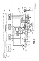
- coating apparatus l0 embodying the invention comprises a vaporizer l2, a pyrolizer l3, a deposition chamber l4 and a condenser l5 physically connected in series by a conduit.
- a chiller 20 is associated with the condenser l5 and a vacuum pump 2l is connected to the condenser in order to maintain the desired pressure conditions within the system and to draw the vapors from one chamber to the next.
- a valve 22 is disposed between the vaporizer l2 and the pyrolizer l3 in a connecting conduit 23.
- a valve 24 is disposed between the deposition chamber l4 and the condenser l5 in a connecting conduit 25.
- Another valve 30 in a conduit 3l is adapted to communicate the deposition chamber l4 to the atmosphere.
- a source 35 of an adhesion promoter is operatively connected to the deposition chamber l4 through a conduit 36, a valve 37 in the conduit 36, and a conduit 38 which communicates the pyrolizer l3 to the deposition chamber l4.
- the vaporizer l2, the pyrolizer l3, the deposition chamber l4, the adhesion promoter source 35, and the valves 22, 24, 30, 37 are provided with heaters (not shown) for controlling the temperature of fluid flowing through the chambers.
- Cyclic di-p-xylylene in powder form is introduced into the cold vaporizer l2 through a door l2a.
- Vaporized dimer passes through the conduit 23 and the valve 22 into the pyrolizer l3 where the vapor is pyrolized to monomeric diradicals.
- the p-xylylene diradical or monomer vapors are then passed into the deposition chamber l4 where they are deposited onto workpiece surfaces located in the chamber. Unreacted dimer vapor is drawn out of the depoisition chamber l4 through the valve 24 and conduit 25 into the condenser l5.
- the polymerization rate in the chamber l4 is measured by a pressure sensor 50.
- the sensor 50 is connected by a conduit 5l to the conduit 38 leading from the pyrolizer l3 into the deposition chamber l4.
- the sensor 50 senses the pressure of the monomer vapor which is an effective way of determining the arrival rate of monomer molecules in the deposition chamber l4.
- Three additional pressure sensors 52-54 monitor the pressure within the vaporizer l2, deposition chamber l4 and the vacuum pump 2l.
- the apparatus l0 includes a computer 55 which includes an interface 56 having circuitry to monitor pressure sensed by the sensors 50, 52, 53, 54, a heater control, and a valve control.
- the heater control is connected to the internal heaters (not shown) of the vaporizer l2, the deposition chamber l4, the adhesion promoter source 35 as well as a number of other heaters used to regulate the temperature of the apparatus l0.
- the valve control is operatively connected to the valves 22, 24, 30, 37.
- a preferred computer 55 comprises an IBM personal computer equipped with a color graphics adapter board, color monitor, and an interface card 56 for monitoring pressures and temperatures and controlling the status of solenoid actuated control valves 22, 24, 30, 37.
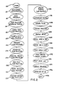
- a control program summarized in the flow diagram of Figure 2 is executed by the computer 55 and controls the coating process as well as updating a user regarding status of that coating process.
- the user turns on the computer and the user is prompted to enter a password.
- the computer 55 executes a program that accesses a number of subroutines.
- the first such subroutine l54 handles the inputting of the password.
- the computer 55 initializes ll2 certain parameters used in a control run of the coating process. The parameters are read from a disk storage into the main memory of the computer.
- control parameters can be set by the user by executing a parameter initialization program separate from the coating control program of Figure 2.
- the parameter initialization routine allows the user to set control parameters such as critical times, temperatures, and pressures used by the computer 55 in assessing the status of the coating run and controlling that run.
- certain specialized subroutines are also initialized l56 by loading the subroutines from disk to enable the computer to access data from the interface 56 that sends and receives inputs to and from the coating apparatus l0.
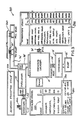
- the program begins ll4 by generating ll6 a display on a viewing screen or monitor 200 ( Figure 3). In generating the display depicted on the viewing screen 200, the computer 55 accesses display data stored on disk.
- the computer 55 checks the status of the valves 22, 24, 30, 37, to determine whether the status of these valves is appropriate (open or closed).
- the computer 55 automatically provides a visual indication of the status of the valves 22, 24, 30, 37. If a valve is open, an arrow (22 ⁇ ) for example) indicates the passage of fluid through the valve. If the valve is closed, the arrow is turned to indicate the fact that no fluid can pass a particular valve. If an error is sensed at this stage of the operation, an error signal is generated on the screen by an error message routine l50 to apprise the user that the status of the system valves is not appropriate for the coating run to begin.
- a "read sensors" subroutine l30 is accessed by the start subroutine ll8.
- the "read sensors” subroutine l30 in turn accesses an even more specialized subroutine l44 that reads data from the l6 bit input/output interface card which preferably is a commercially available Hewlett-Packard no. 3497 interface card.
- the computer 55 enters a close and lock routine l20.
- a message is generated on a cycle line 220 ( Figure 3) by a cycle line print subroutine l52 instructing the user to close and lock the deposition chamber door through which workpieces to be coated were inserted into the deposition chamber.
- the close and lock routine l20 checks the door by instructing the interface card 56 to latch data indicative of the status of a microswitch that senses when the door is closed.
- the close and lock routine l20 checks the speed of rotation of a motor driven rotor within the chamber l4 that rotates workpieces supported inside the chamber.
- the routine l20 also closes the valve 30 (and changes the orientation of the arrow 30 ⁇ ) and activates the pump 2l to lower the pressure within the deposition chamber l4.
- a vaporizer valve 262 ( Figure 3) connects the vaporizer l2 to the pump 2l so that the pressure in the vaporizer is also lowered.
- a status message is generated on a status line 230 ( Figure 3) by a status message subroutine l48 telling the user that the pump is lowering the pressure within the chambers l2, l4. Also, the sensor reading routine l30 and a display update routine l34 are accessed to acquire and update pressure values indicated in a pressure update portion 235 of the screen 200. The computer 55 continually monitors the chamber pressures (and displays these pressures on the screen) until the pump 2l has reduced the pressures to acceptable levels.
- the computer 55 makes decisions based upon voltages input through the interface 56. In order to display the pressures and temperatures in units the user can comprehend, the computer 55 converts these voltages to microinches of mercury (pressure) and degrees celsius (temperature).
- a preheat routine l22 is entered by the computer 55 once the chamber pressure is low enough.
- the cycle line 220 is updated with a message "PREHEAT CYCLE.” This message is also sent to a hard copy printer 70. From this point on in the coating process, this printer 70 prints out sensed temperature, pressures, and cycle times under control of a printer update routine l40. At the same time a printer output is generated, a disk file stored on a disk storage device 7l is updated so that two permanent records of the run are created.
- a timer update routine l38 continually times the passage of time from the beginning ll8 of the program.
- the preheat subroutine l22 generates outputs to heaters and monitors the performance of those heaters via the interface card 50.
- the apparatus l0 comprises a plurality of thermocouple temperature sensors that sense the temperature of components (the deposition chamber, for example) and transmit this information to the computer 55.
- the sensor input routine l30 and a heater control output routine l32 are continually accessed until the sensed temperatures fall within a predetermined range.
- the heater control and valve control operations both access a special interface output routine l46 to transmit control signals from the computer to the apparatus. Table I below indicates control values for these temperatures in degrees Celsius.
- a temperature update portion 240 of the screen 200 is updated by the display update routine l34.
- the computer progresses to an adhesion promoting routine l24.
- the screen cycle line 220 and printer are updated to indicate a new cycle has been entered.
- the computer 55 sequentially checks the pump pressure, closes the valve 24 between the pump 2l and chamber l4 and opens the adhesion valve 37 causing the workpieces inside the chamber to be coated with an adhesion promotor.
- the Figure 3 depiction of the viewing screen is representative of data presented to the user during the adhesion promotion cycle.
- the adhesion promotor is an organo functional sylane commercially available under the designation Al74.
- Al74 an adhesion promoting heater is turned on to promote adhesion flow to the chamber l4.
- a vaporizer heater is turned on and the vaporizer valve 22 is opened.
- the timing of these steps is controlled by the computer 55 and is displayed on a cycle line 245 ( Figure 3) that is updated on the screen 200.
- the valve 37 is closed and the vaporizer is brought up to temperature during a timed vaporizor heating cycle.
- a final subroutine in the coating process is a coating cycle routine l26.
- the computer 55 continuously senses data, accesses the heater control routine l32, updates the display temperatures and pressures l34 and executes a vaporizer control routine l36.
- the vaporizer control routine is a specialized routine that controls vaporizer temperatures and therefore pressure in accordance with the disclosure of the '889 prior art patent to Riley.
- An end in the coating cycle is indicated by a rather precipitous drop in post-pyrolizer pressure measured by the sensor 50.
- a control threshold (entered via the parameter initialization program)
- coating is complete and the computer enters an end run subroutine l28.
- the cycle line 220 is updated to indicate an "END OF PROCESS" has been reached.
- the printer 70 also gives this indication and all valves and heaters are closed and turned off.
- the status line is updated to indicate the coating run has been completed and the user is prompted to "press any key to start another run" by a prompt on an error line 250.
- This is generated by an error/sound alarm routine l50 that in addition to printing on the error line 250, generates an audible alarm via a computer speaker.
- the available alarm routine l50 controls the duration, pitch, and intensity of each warning so that the type of problem can be discerned and, if needed, appropriate action taken.
- the error line 250 is printed to whenever an error is detected.
- a message is displayed telling the user to check the rotor.
- One last routine l42 can be accessed at any time by the user if he or she wishes to abort a coating run. By pressing a special function key on the computer keyboard the coating run is aborted. A message is displayed that the user aborted the run and the computer branches to the end run subroutine l28.
- the end run routine l28 Once the end run routine l28 is completed the user can initiate another coating run or can end l58 the operation by turning off the computer 55. If the user starts another coating run, the preheat routine where the apparatus heaters are energized will take less time and subsequent run times (RT) will be shorter.
- RT run times
- the user At the end of each run the user has a hard copy printout of the periodically sensed pressures and temperatures for the coating run as well as a running indication of elapsed time since the beginning of the main program, run time (RT), and the time for the coating cycle (CT).
- the temperatures are recorded in degrees Celsius, the pressures in microns of mercury and the elapsed time in hours and minutes.
- a preferred screen 200 comprises a color monitor.
- the apparatus components are outlined in a color different from a border color for the tables of temperature and pressure and the message areas.
- the color of the temperature condition column changes if the sensed temperatures deviate above or below the Table I ranges. This color control in combination with audible warnings through the computer speaker inform the user when the system deviates from normal operation.
- Two valves 260, 262 depicted on the screen 200 correspond to valves for adding adhesion promotor to the adhesion source 35 and for connecting the vaporizer l2 to the pump 2l. These valves are presently manually opened and closed. Their status, however, is automatically sensed and it is within the scope of the invention to automatically control their status via the computer 55.
Landscapes
- Physics & Mathematics (AREA)
- General Physics & Mathematics (AREA)
- Engineering & Computer Science (AREA)
- Automation & Control Theory (AREA)
- Physical Vapour Deposition (AREA)
- Application Of Or Painting With Fluid Materials (AREA)
- Chemical Vapour Deposition (AREA)
Applications Claiming Priority (2)
| Application Number | Priority Date | Filing Date | Title |
|---|---|---|---|
| US06/849,473 US4683143A (en) | 1986-04-08 | 1986-04-08 | Method and apparatus for automated polymeric film coating |
| US849473 | 1986-04-08 |
Publications (2)
| Publication Number | Publication Date |
|---|---|
| EP0241112A2 true EP0241112A2 (de) | 1987-10-14 |
| EP0241112A3 EP0241112A3 (de) | 1988-11-02 |
Family
ID=25305827
Family Applications (1)
| Application Number | Title | Priority Date | Filing Date |
|---|---|---|---|
| EP87301005A Withdrawn EP0241112A3 (de) | 1986-04-08 | 1987-02-04 | Verfahren und Vorrichtung zum automatisierten Beschichten mit Kunststoffilmen |
Country Status (6)
| Country | Link |
|---|---|
| US (1) | US4683143A (de) |
| EP (1) | EP0241112A3 (de) |
| JP (1) | JPS62238361A (de) |
| KR (1) | KR870010429A (de) |
| AU (1) | AU6237886A (de) |
| PH (1) | PH23213A (de) |
Families Citing this family (42)
| Publication number | Priority date | Publication date | Assignee | Title |
|---|---|---|---|---|
| JPS62273714A (ja) * | 1986-05-21 | 1987-11-27 | Clarion Co Ltd | 有機金属ガス供給方法および装置 |
| US5121706A (en) * | 1987-10-16 | 1992-06-16 | The Curators Of The University Of Missouri | Apparatus for applying a composite insulative coating to a substrate |
| JPH01215976A (ja) * | 1988-02-24 | 1989-08-29 | Fujitsu Ltd | 自己診断機能を具備したスパッタリング装置 |
| US5167718A (en) * | 1988-06-23 | 1992-12-01 | Jeffrey Stewart | Parylene deposition chamber and method of use |
| US5078091A (en) * | 1988-06-23 | 1992-01-07 | Jeffrey Stewart | Parylene deposition chamber and method of use |
| US4935261A (en) * | 1988-10-17 | 1990-06-19 | Micro Robotics Systems Inc. | Method for controlling accurate dispensing of adhesive droplets |
| JP2906624B2 (ja) * | 1990-09-27 | 1999-06-21 | 株式会社島津製作所 | 薄膜形成装置 |
| US5268033A (en) * | 1991-07-01 | 1993-12-07 | Jeffrey Stewart | Table top parylene deposition chamber |
| US5264039A (en) * | 1992-02-24 | 1993-11-23 | Union Carbide Chemicals & Plastics Technology Corporation | Vapor deposition apparatus |
| US5355832A (en) * | 1992-12-15 | 1994-10-18 | Advanced Surface Technology, Inc. | Polymerization reactor |
| US5424097A (en) * | 1993-09-30 | 1995-06-13 | Specialty Coating Systems, Inc. | Continuous vapor deposition apparatus |
| US5312489A (en) * | 1993-09-30 | 1994-05-17 | Union Carbide Chemicals & Plastics Technology Corporation | Rotary fixture for vapor deposition coating apparatus |
| US5488833A (en) * | 1994-09-26 | 1996-02-06 | Stewart; Jeffrey | Tangential flow cold trap |
| RU2129475C1 (ru) * | 1995-04-03 | 1999-04-27 | Российская национальная библиотека | Устройство для нанесения поли-пара-ксилиленовых покрытий |
| US5538758A (en) * | 1995-10-27 | 1996-07-23 | Specialty Coating Systems, Inc. | Method and apparatus for the deposition of parylene AF4 onto semiconductor wafers |
| US5536322A (en) * | 1995-10-27 | 1996-07-16 | Specialty Coating Systems, Inc. | Parylene deposition apparatus including a heated and cooled support platen and an electrostatic clamping device |
| US5536319A (en) * | 1995-10-27 | 1996-07-16 | Specialty Coating Systems, Inc. | Parylene deposition apparatus including an atmospheric shroud and inert gas source |
| US5556473A (en) * | 1995-10-27 | 1996-09-17 | Specialty Coating Systems, Inc. | Parylene deposition apparatus including dry vacuum pump system and downstream cold trap |
| US5536321A (en) * | 1995-10-27 | 1996-07-16 | Specialty Coating Systems, Inc. | Parylene deposition apparatus including a post-pyrolysis filtering chamber and a deposition chamber inlet filter |
| US5879808A (en) * | 1995-10-27 | 1999-03-09 | Alpha Metals, Inc. | Parylene polymer layers |
| US5709753A (en) * | 1995-10-27 | 1998-01-20 | Specialty Coating Sysetms, Inc. | Parylene deposition apparatus including a heated and cooled dimer crucible |
| US5536317A (en) * | 1995-10-27 | 1996-07-16 | Specialty Coating Systems, Inc. | Parylene deposition apparatus including a quartz crystal thickness/rate controller |
| US5534068A (en) * | 1995-10-27 | 1996-07-09 | Specialty Coating Systems, Inc. | Parylene deposition apparatus including a tapered deposition chamber and dual vacuum outlet pumping arrangement |
| US5806319A (en) * | 1997-03-13 | 1998-09-15 | Wary; John | Method and apparatus for cryogenically cooling a deposition chamber |
| US5841005A (en) * | 1997-03-14 | 1998-11-24 | Dolbier, Jr.; William R. | Parylene AF4 synthesis |
| US6051276A (en) * | 1997-03-14 | 2000-04-18 | Alpha Metals, Inc. | Internally heated pyrolysis zone |
| US5882725A (en) * | 1997-07-01 | 1999-03-16 | Para Tech Coating, Inc. | Parylene deposition chamber including eccentric part tumbler |
| DE69841645D1 (de) * | 1998-05-28 | 2010-06-10 | Ulvac Inc | Vakuumverdampfungseinrichtung |
| EP0962260B1 (de) * | 1998-05-28 | 2005-01-05 | Ulvac, Inc. | Verdampfungssystem für organisches Material |
| US6275649B1 (en) | 1998-06-01 | 2001-08-14 | Nihon Shinku Gijutsu Kabushiki Kaisha | Evaporation apparatus |
| US6428848B1 (en) | 1998-08-06 | 2002-08-06 | Toray Industries, Inc. | Method for producing a metal evaporated article |
| US6473564B1 (en) | 2000-01-07 | 2002-10-29 | Nihon Shinku Gijutsu Kabushiki Kaisha | Method of manufacturing thin organic film |
| US20030196680A1 (en) * | 2002-04-19 | 2003-10-23 | Dielectric Systems, Inc | Process modules for transport polymerization of low epsilon thin films |
| US6737224B2 (en) | 2001-04-17 | 2004-05-18 | Jeffrey Stewart | Method of preparing thin supported films by vacuum deposition |
| JP3828821B2 (ja) * | 2002-03-13 | 2006-10-04 | 株式会社堀場エステック | 液体材料気化供給装置 |
| JP2004207687A (ja) * | 2002-12-10 | 2004-07-22 | Sharp Corp | 半導体製造装置とそれを用いた半導体製造方法 |
| US7883745B2 (en) | 2007-07-30 | 2011-02-08 | Micron Technology, Inc. | Chemical vaporizer for material deposition systems and associated methods |
| JP5439097B2 (ja) * | 2009-09-08 | 2014-03-12 | 東京応化工業株式会社 | 塗布装置及び塗布方法 |
| JP5639816B2 (ja) * | 2009-09-08 | 2014-12-10 | 東京応化工業株式会社 | 塗布方法及び塗布装置 |
| JP5469966B2 (ja) * | 2009-09-08 | 2014-04-16 | 東京応化工業株式会社 | 塗布装置及び塗布方法 |
| JP5719546B2 (ja) * | 2009-09-08 | 2015-05-20 | 東京応化工業株式会社 | 塗布装置及び塗布方法 |
| CN103454179B (zh) * | 2013-08-15 | 2015-04-01 | 贵州航天精工制造有限公司 | 一种测定航空紧固件材料蒙乃尔合金中镍含量的方法 |
Family Cites Families (2)
| Publication number | Priority date | Publication date | Assignee | Title |
|---|---|---|---|---|
| US4495889A (en) * | 1982-11-24 | 1985-01-29 | Riley Thomas J | Polymeric film coating apparatus |
| US4518623A (en) * | 1982-11-24 | 1985-05-21 | Riley Thomas J | Polymeric film coating method with continuous deposition pressure control |
-
1986
- 1986-04-08 US US06/849,473 patent/US4683143A/en not_active Expired - Fee Related
- 1986-09-05 AU AU62378/86A patent/AU6237886A/en not_active Abandoned
- 1986-09-12 KR KR1019860007675A patent/KR870010429A/ko not_active Withdrawn
- 1986-10-03 PH PH34328A patent/PH23213A/en unknown
- 1986-12-17 JP JP61299004A patent/JPS62238361A/ja active Pending
-
1987
- 1987-02-04 EP EP87301005A patent/EP0241112A3/de not_active Withdrawn
Also Published As
| Publication number | Publication date |
|---|---|
| PH23213A (en) | 1989-06-06 |
| JPS62238361A (ja) | 1987-10-19 |
| US4683143A (en) | 1987-07-28 |
| EP0241112A3 (de) | 1988-11-02 |
| AU6237886A (en) | 1987-10-15 |
| KR870010429A (ko) | 1987-11-30 |
Similar Documents
| Publication | Publication Date | Title |
|---|---|---|
| EP0241112A2 (de) | Verfahren und Vorrichtung zum automatisierten Beschichten mit Kunststoffilmen | |
| US7891353B2 (en) | Breathing assistance device with several secure respirator modes and associated method | |
| US5669877A (en) | Systems and methods for automated testing of medical equipment | |
| CA1186512A (en) | Automatic co.sub.2 removal system and operation thereof | |
| WO1996006038A1 (en) | Vapour recovery system for a fuel delivery system | |
| US5620608A (en) | Information entry validation system and method for a dialysis machine | |
| US5562614A (en) | Programmable manifold system for automatic fluid delivery | |
| JPH08504116A (ja) | 腎臓透析法及び装置 | |
| CA2663732A1 (en) | Method and system for controlled infusion of therapeutic substances | |
| JPH06501188A (ja) | 透析ユニットを監視する方法 | |
| JP2001276214A (ja) | 較正方法及び制御方法 | |
| JPH09510054A (ja) | 遠隔監視制御可能な機器のための装置 | |
| EP1724530A1 (de) | System und Verfahren zur Drainage von Wasser aus einem Dampfofen | |
| JP2010119491A (ja) | 滅菌装置 | |
| TW419385B (en) | Process for controlling a blood epuration device | |
| JPH0853961A (ja) | 電子組合わせロック | |
| JPH1057480A (ja) | 携帯用輸液滴下間隔管理装置 | |
| CN116734160B (zh) | 用于液氮加注的方法及装置、液氮加注站、存储介质 | |
| KR930002032B1 (ko) | 자동현금 거래장치의 조작 유도장치 | |
| Friesdorf et al. | Decision making in high dependency environments—can we learn from modern industrial management models? | |
| US20250075322A1 (en) | Method of monitoring liquid raw material and gas supply device | |
| WO2004020030A1 (en) | Breathing assistance device with several secure respirator modes and associated method | |
| CN116268974B (zh) | 一种电热水壶底座控制方法、系统、存储介质及智能终端 | |
| JP3507966B2 (ja) | 蒸気加熱装置 | |
| KR100396617B1 (ko) | 전자레인지조리제어방법및장치 |
Legal Events
| Date | Code | Title | Description |
|---|---|---|---|
| PUAI | Public reference made under article 153(3) epc to a published international application that has entered the european phase |
Free format text: ORIGINAL CODE: 0009012 |
|
| AK | Designated contracting states |
Kind code of ref document: A2 Designated state(s): DE GB IT |
|
| PUAL | Search report despatched |
Free format text: ORIGINAL CODE: 0009013 |
|
| AK | Designated contracting states |
Kind code of ref document: A3 Designated state(s): DE GB IT |
|
| 17P | Request for examination filed |
Effective date: 19890502 |
|
| 17Q | First examination report despatched |
Effective date: 19900212 |
|
| STAA | Information on the status of an ep patent application or granted ep patent |
Free format text: STATUS: THE APPLICATION IS DEEMED TO BE WITHDRAWN |
|
| 18D | Application deemed to be withdrawn |
Effective date: 19910522 |