EP0240922B1 - Vorrichtung zum Laden einer Kassette für ein Aufnahme- und/oder Wiedergabegerät - Google Patents
Vorrichtung zum Laden einer Kassette für ein Aufnahme- und/oder Wiedergabegerät Download PDFInfo
- Publication number
- EP0240922B1 EP0240922B1 EP87104827A EP87104827A EP0240922B1 EP 0240922 B1 EP0240922 B1 EP 0240922B1 EP 87104827 A EP87104827 A EP 87104827A EP 87104827 A EP87104827 A EP 87104827A EP 0240922 B1 EP0240922 B1 EP 0240922B1
- Authority
- EP
- European Patent Office
- Prior art keywords
- cassette
- cassette holder
- arm
- holder
- bracket
- Prior art date
- Legal status (The legal status is an assumption and is not a legal conclusion. Google has not performed a legal analysis and makes no representation as to the accuracy of the status listed.)
- Expired - Lifetime
Links
- 230000007246 mechanism Effects 0.000 title claims description 59
- 230000037431 insertion Effects 0.000 claims description 13
- 238000003780 insertion Methods 0.000 claims description 13
- 230000002265 prevention Effects 0.000 claims description 7
- 238000010276 construction Methods 0.000 description 2
- 230000007812 deficiency Effects 0.000 description 1
- 238000001514 detection method Methods 0.000 description 1
- 230000000694 effects Effects 0.000 description 1
Images


Classifications
-
- G—PHYSICS
- G11—INFORMATION STORAGE
- G11B—INFORMATION STORAGE BASED ON RELATIVE MOVEMENT BETWEEN RECORD CARRIER AND TRANSDUCER
- G11B15/00—Driving, starting or stopping record carriers of filamentary or web form; Driving both such record carriers and heads; Guiding such record carriers or containers therefor; Control thereof; Control of operating function
- G11B15/60—Guiding record carrier
- G11B15/66—Threading; Loading; Automatic self-loading
-
- G—PHYSICS
- G11—INFORMATION STORAGE
- G11B—INFORMATION STORAGE BASED ON RELATIVE MOVEMENT BETWEEN RECORD CARRIER AND TRANSDUCER
- G11B15/00—Driving, starting or stopping record carriers of filamentary or web form; Driving both such record carriers and heads; Guiding such record carriers or containers therefor; Control thereof; Control of operating function
- G11B15/675—Guiding containers, e.g. loading, ejecting cassettes
- G11B15/67544—Guiding containers, e.g. loading, ejecting cassettes with movement of the cassette parallel to its main side and subsequent movement perpendicular thereto, i.e. front loading
- G11B15/67547—Guiding containers, e.g. loading, ejecting cassettes with movement of the cassette parallel to its main side and subsequent movement perpendicular thereto, i.e. front loading the two movements being made by the cassette holder
- G11B15/67549—Guiding containers, e.g. loading, ejecting cassettes with movement of the cassette parallel to its main side and subsequent movement perpendicular thereto, i.e. front loading the two movements being made by the cassette holder with servo control
-
- G—PHYSICS
- G11—INFORMATION STORAGE
- G11B—INFORMATION STORAGE BASED ON RELATIVE MOVEMENT BETWEEN RECORD CARRIER AND TRANSDUCER
- G11B15/00—Driving, starting or stopping record carriers of filamentary or web form; Driving both such record carriers and heads; Guiding such record carriers or containers therefor; Control thereof; Control of operating function
- G11B15/675—Guiding containers, e.g. loading, ejecting cassettes
Definitions
- the present invention relates to a cassette loading mechanism for use in magnetic recording and/or reproducing apparatus such as a video tape recorder.
- the present invention is suitably applied to a so-called front loading type cassette loading mechanism in which a cassette holder adapted to hold a tape cassette is moved vertically and horizontally by utilizing the driving force of a motor, that is, the cassette holder (tape cassette) is first moved in a horizontal direction and then moved in a vertical direction.
- FR-A-2 253 250 discloses a magnetic tape recorder with a cassette holder to maintain a cassette, means along which said cassette holder is guided from a first position to a second position and a driving mechanism for said cassette holder disposed between said means and said cassette holder.
- the driving means is supplied with power from a power source.
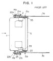
- front loading mechanism An example of this front loading type cassette loading mechanism (hereinafter referred to as "front loading mechanism") is constituted in the manner illustrated in Figs. 1 to 4.
- Fig. 1 shows a schematic plan view of a conventional front loading mechanism
- Fig. 2 shows a side view of this mechanism seen from the left hand side
- Fig. 3 shows an exploded perspective view of an essential part of this mechanism
- Fig. 4 shows a cross-sectional view of this essential part.
- the front loading mechanism has a cassette holder 2 mounted between a left side bracket 3a and a right side bracket 3b.
- This cassette holder 2 is supported by means of shafts 11a, 11b, 12a and 12b, and rollers 14a, 14b, 15a and 15b such as to be movable along L-shaped guide slits G1, G1 and G3, G3 formed in the left and right side brackets 3a and 3b which are fixed to a main chassis 3 and acts as a member for positioning the entire part of the cassette loading mechanism.
- the shafts 11a, 11b, 12a and 12b are embedded in both side walls of the holder 2.
- Rollers 14a, 14b, 15a and 15b are fitted to the shafts 11a, 11b, 12a and 12b, and parts of these rollers are engaged with the guide slits G1 and G2 of the brackets 3a and 3b.
- Drive arm 22a and 22b and drive gears 21a and 21b are attached to a synchronizing shaft 25, and these arms have elongated holes H into which the rollers 14a and 14b are inserted.
- the drive gears 21a and 21b are adapted to be rotated by the driving force of a motor (not shown).
- the synchronizing shaft 25 is rotatably mounted on the left and right side brackets 3a and 3b.
- the drive arm 22a When the gear 21a is rotated anticlockwisely, the drive arm 22a is also rotated in the same direction while turning the gear 21b and the driving arm 22b, and the arm 22a applies a force to the cassette holder 2 in the leftward direction, so that the holder 2 is transported in the horizontal direction toward the inner part of the apparatus while carrying the cassette 1 and being guided along the guide slits G1, G2. After being moved a predetermined distance, the cassette holder 2 is guided along vertical portions of the guide slits G1 and G2 so as to be transported vertically and downwardly.
- a magnetic tape (not shown) incorporated in the cassette 1 is extracted by a tape loading mechanism (not shown) of the video tape recorder to be wound around a cylinder (not shown) having recording and reproducing heads, thereby effecting recording on the magnetic tape and reproduction of the same.
- rotary members are disposed in positions in which they do not interfere with a cassette lid opening and closing mechanism and a cassette insertion error prevention mechanism, thereby enabling reduction in the width of the cassette loading mechanism and in the size of the magnetic recording and/or reproducing apparatus.
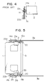
- rollers 14a, 15b and rollers 14b and 15b are engaged with guide slits G (described later in detail) formed in a pair of left and right brackets 3A and 3B which are fixed to the main chassis 3 of a magnetic recording and/or reproducing apparatus.
- guide slits G (described later in detail) formed in a pair of left and right brackets 3A and 3B which are fixed to the main chassis 3 of a magnetic recording and/or reproducing apparatus.
- These rollers are driven along the guide slits G by a left drive arm 22a and a right drive arm 22b provided as rotary members.
- the drive arm 22a is disposed between the holder 2 and the bracket 3A, and the drive arm 22b is disposed between the holder 2 and the bracket 3B.
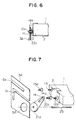
- the detail of the left hand portion of this cassette loading mechanism will be described with reference to Figs. 6 and 7.
- the right hand portion has the same construction with respect to the drive arms and other portions, and the description of the same is therefore omitted.
- a cassette holder driving means including the drive arm 22a is disposed between the cassette 1, the holder 2 and the bracket 3A.
- the roller 14a which is rotatably mounted on a shaft 12a embedded in the holder 2 passes through an elongated hole H formed in the drive arm 22a and is engaged with an L-shaped guide slit G1 formed in the bracket 3A.
- the roller 15a which is rotatably mounted on a shaft 11a is engaged with an L-shaped guide slit G2 formed in the bracket 3A.
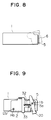
- a gear 21a which is mounted on a shaft 25 is inserted into a hole 3A ⁇ formed in the bracket 3A, as shown in Fig.
- a cassette insertion error prevention mechanism (described later) is disposed between the holder 2 and the bracket 3A, and a cassette lid opening and closing mechanism (described later) is disposed between the holder 2 and the bracket 3B. Therefore, the distance between the brackets 3A and 3B and the opposite side walls of the holder 2 is the same as that in the conventional cassette loading mechanism and cannot be reduced. However, it is possible to reduce the total width of the cassette loading mechanism of the present invention by disposing the drive arms 22a and 22b inside the brackets 3A and 3B. It goes without saying that the drive arms 22a and 22b do not interfere with the cassette insertion error prevention mechanism and the cassette lid opening and closing mechanism.
- the operation of the thus constructed cassette loading mechanism is in accordance with that of the conventional mechanism.
- the rollers 14a and 15a of the holder 2 are driven by the drive arm 22a along the guide slit G1, and the rollers 14b and 15b are driven in synchronism therewith by the drive arm 22b along the guide slit of the bracket 3B, thereby transferring the cassette 1 inserted into the holder 2 through the insertion opening to its predetermined position in the main body.
- the drive arms 22a and 22b are rotated when driven by the motor or the like.
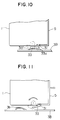
- the cassette 1 is provided, as is well known, with a lid 5 adapted for protecting a tape 6 incorporated in the cassette 1, and is also provided with a switch member 31 (refer to Fig. 10) for releasing a lock of the lid 5.
- the lid 5 is opened when the magnetic recording and/or reproducing apparatus effects recording or reproducing.
- the lid 5 is preliminarily opened by several millimeters before being fully opened.
- the tape 6 is extracted by guide rollers to be wound around a cylinder after the cassette 1 has been placed in its predetermined position. The tape 6 is driven while being pinched between a capstan and a pinch roller.
- the lid 5 may be designed to be slightly opened during the horizontal movement of the cassette 1 so as to be adjusted to the level of the lower end of the tape 6, thereby enabling the cassette loading mechanism to be reduced in height while ensuring that the tape 6 may pass over the guide rollers, the capstan and other members.
- a switch arm 33 which is adapted for opening and closing the lid 5.
- this arm 33 is supported by rotary support shafts disposed on the upper and lower sides of the holder 2 such as to be rotatable around these rotary support shafts.
- Fig. 10 illustrates the initial state of the operation of transferring the cassette 1, that is, the state in which the cassette 1 has been inserted or an unloading operation has been completed.
- a slide portion in the form of the profile of a boat formed in the upper part of the switch arm 33 rides on a cut and raised portion (projection) 3B ⁇ formed on the bracket 3B, and a contact portion 33a which is formed at the center of the switch arm 33 such as to be capable of contacting the switch member 31 is not yet in contact with the same. This is because, if the switch member 31 is constantly in contact with the switch arm 33, the operator will be given the feeling that the cassette 1 is caught when inserting or removing the cassette 1.
- the switch arm 33 is set apart in order to eliminate this feeling during the operation of inserting or removing the cassette 1.
- the switch arm 33 is parted from the raised portion of the bracket 3B and a turning force acting in the anticlockwise direction indicated by the arrow in Fig. 11 imparted thereto, as a result of which the switch member 31 is pressed to enable the lid 5 to be opened or closed.
- a spring 32 is stretched between an opening and closing arm 20 (described below) and the switch arm 33, thereby applying an urging force to the opening and closing arm 20 in the clockwise direction as viewed in Fig. 12 and applying an urging force to the switch arm 33 in the anticlockwise direction as viewed in Fig. 11.
- the opening and closing arm 20 is rotatably attached to the shaft 11b and is maintained in a position in which the lower end thereof is generally in contact with the lid 5 of the cassette 1.
- the upper end of the opening and closing arm 20 contacts a ceiling plate 7 of the cassette loading mechanism and turns by virtue of the turning force imparted to it in the anticlockwise direction as indicated by the arrow in Fig. 12, so that the lid 5 which has been in contact with the lower end of the opening and closing arm 20 is opened by several millimeters, as shown in Fig. 12.
- the relationship between the positions of the cassette lid opening and closing mechanism and the drive arm 22b is as illustrated in Fig. 13.
- the opening and closing arm 20 and the switch arm 33 are placed in positions that are comparatively remote from the insertion opening (not shown).
- the roller 14b is placed near the insertion opening, so that the drive arm 22b does not interfere with the switch arm 33.
- a hook arm 35 is rotatably attached to the shaft 11a and is constantly urged in the anticlockwise direction by a spring (not shown).
- a hook portion 35a formed at the upper end of the hook arm 35 is engaged with the ceiling plate 7, so that, if an object other than the cassette 1 is inserted or if the cassette 1 is inserted upside down, the hook portion 35a acts as a stopper to stop the cassette 1 from being transported.
- the lid 5 of the cassette 1 is provided with a slit 1a for detecting the completed state of the operation of inserting the cassette 1.
- the hook arm 35 As the cassette 1 is inserted, the hook arm 35 is brought into contact with the cassette 1 in this slit and is turned about the shaft 11a. In accordance with this operation, the hook portion of the hook arm 35 is moved downwardly, as shown in Fig. 16, and the engagement with the ceiling plate 7 is thereby released, thereby enabling the cassette to be transported.
Landscapes
- Automatic Tape Cassette Changers (AREA)
- Casings For Electric Apparatus (AREA)
Claims (4)
- Vorrichtung zum Laden einer Kassette für ein magnetisches Aufnahme- und/oder Wiedergabegerät, welche aufweist:
eine Kassettenhaltevorrichtung (2) zum Aufnehmen einer Bandkassette (1) mit einem Schalterelement (31), welches in einer Seitenwand der Kassette (1) angeordnet und zum Lösen eines Schlosses eines Kassettendeckels (5) angepaßt ist;
eine Klammer (3a, 3b) mit einem Führungsschlitz (G₁, G₂), entlang dem die Kassettenhaltevorrichtung (2) von einer ersten Position zu einer zweiten Position geführt wird, wobei die Klammer (3a, 3b) die Kassettenhaltevorrichtung (2) aufnimmt;
einen Kassettenhaltevorrichtung-Antriebsmechanismus zum Antreiben der Kassettenhaltevorrichtung (2) entlang des Führungsschlitzes (G₁, G₂), der in dieser Klammer (3a, 3b) ausgebildet ist, wobei der Kassettenhaltevorrichtung-Antriebsmechanismus eine Kassettenhaltevorrichtung-Antriebseinrichtung beinhaltet, die zwischen der Kassettenhaltevorrichtung (2) und der Klammer (3a, 3b) angeordnet und an die Kassettenhaltevorrichtung (2) angeschlossen ist;
eine Stromquelle; und
Stromübertragungseinrichtung zum Antreiben der Kassettenhaltevorrichtung-Antriebseirrichtung, während sie mit Strom von dieser Stromquelle versorgt wird,
dadurch gekennzeichnet, daß weiterhin aufgewiesen wird:
ein Öffnungs- und Schließmechanismus eines Kassettendeckels (5), der zwischen der Kassettenhaltevorrichtung (2) und der Klammer (3a, 3b) angeordnet ist, wobei der Öffnungs- und Schließmechanismus für den Kassettendeckel (5) enthält:
einen Schalterarm (33), der drehbar und axial auf der Kassettenhaltevorrichtung (2) gestutzt und zum Betätigen des Schalterelements (31) angepaßt ist, so daß es möglich ist, den Kassettendeckel (5) zu Öffnen oder zu schließen;
einen Deckelöffnungs- und Schließarm (20), der angepaßt ist zum Öffnen und Schließen des Kassettendeckels;
eine einzige Spannfeder (32), die zwischen dem Deckelöffnungs- und Schließarm (20) und dem Schalterarm (33) gestreckt ist;
einen Vorsprung (3B), der an der Klammer (3a, 3b) ausgebildet ist, wobei der Vorsprung so arbeitet, daß er den Schalterarm (33) dreht, damit das Schalterelement (31) gelöst wird, wenn die Kassette (1) zum ersten Mal in die Kassettenhaltevorrichtung (2) eingefügt wird, und wobei der Vorsprung so arbeitet, daß der Schalterarm (33) gedreht wird, damit das Schalterelement nach unten gedrückt wird, wenn die Kassettenhaltevorrichtung (2) daraufhin zu einer vorbestimmten Position transportiert wird; und
eine Deckenplatte (7), welche den Deckelöffnungs- und Schließarm (20) kontaktiert und dreht, damit der Kassettendeckel (5) der Kassette (1) um ein vorbestimmtes Ausmaß nach oben geöffnet wird, wenn die Kassettenhaltevorrichtung (2) weiter in der horizontalen Richtung bewegt wird. - Vorrichtung zum Laden einer Kassette nach dem Oberbegriff von Anspruch 1, welche weiterhin aufweist:
einen Kassetteneinfügung-Fehlerverhinderungsmechanismus, der zwischen der Kassettenhaltevorrichtung (2) und der Klammer (3a, 3b) angeordnet ist, wobei der Kassetteneinfügung-Fehlerverhinderungsmechanismus beinhaltet:
eine Stoppvorrichtung (35a), einen Hakenarm (35), der drehbar an der Klammer (3a, 3b) befestigt ist, wobei ein Ende des Hakenarms (35) auf die Rückfläche der Kassette (1) weist und das andere Ende auf die Stoppvorrichtung (35a) weist. - Vorrichtung zum Laden einer Kassette nach einem der vorhergehenden Ansprüche, wobei der Kassettenhaltevorrichtung (2)-Antriebsmechanismus an die Stromübertragungseinrichtung angeschlossen und versehen ist mit:
einem Antriebsarm (22a, 22b), der durch die Stromübertragungseinrichtung gedreht wird und ein längliches Loch (H) hat; und
einem Eingriffselement (G), welches an der Kassettenhaltevorrichtung (2) befestigt ist und im Eingriff ist mit dem Führungsschlitz (G₁, G₂) der Klammer (3a, 3b) durch das in dem Arm (33) ausgebildete längliche Loch. - Vorrichtung zum Laden einer Kassette nach einem der vorhergehenden Ansprüche, wobei das Eingriffselement eine an der Kassettenhaltevorrichtung (2) fest angebrachte Welle (11b) und eine an die Welle (11b) angepaßte Walze (14b) beinhaltet.
Applications Claiming Priority (2)
| Application Number | Priority Date | Filing Date | Title |
|---|---|---|---|
| JP61080171A JP2544345B2 (ja) | 1986-04-09 | 1986-04-09 | カセツト装着装置 |
| JP80171/86 | 1986-04-09 |
Publications (3)
| Publication Number | Publication Date |
|---|---|
| EP0240922A2 EP0240922A2 (de) | 1987-10-14 |
| EP0240922A3 EP0240922A3 (en) | 1989-10-25 |
| EP0240922B1 true EP0240922B1 (de) | 1992-11-04 |
Family
ID=13710884
Family Applications (1)
| Application Number | Title | Priority Date | Filing Date |
|---|---|---|---|
| EP87104827A Expired - Lifetime EP0240922B1 (de) | 1986-04-09 | 1987-04-01 | Vorrichtung zum Laden einer Kassette für ein Aufnahme- und/oder Wiedergabegerät |
Country Status (5)
| Country | Link |
|---|---|
| US (1) | US4794477A (de) |
| EP (1) | EP0240922B1 (de) |
| JP (1) | JP2544345B2 (de) |
| KR (1) | KR910000570B1 (de) |
| DE (1) | DE3782444T2 (de) |
Families Citing this family (12)
| Publication number | Priority date | Publication date | Assignee | Title |
|---|---|---|---|---|
| JPH0656707B2 (ja) * | 1987-07-01 | 1994-07-27 | 富士写真フイルム株式会社 | 磁気テ−プカセット検査方法および装置 |
| DE311390T1 (de) * | 1987-10-07 | 1989-11-16 | Victor Company Of Japan, Ltd., Yokohama, Kanagawa | Bandkassettenladesystem. |
| US5060094A (en) * | 1987-11-20 | 1991-10-22 | Goldstar Co., Ltd. | Cassette loading apparatus for digital audio tape recorder |
| EP0506143B1 (de) * | 1987-12-09 | 1995-04-19 | Mitsubishi Denki Kabushiki Kaisha | Bandkassette-Lademechanismus in einem Bandwiedergabegerät |
| JPH02177163A (ja) * | 1988-12-28 | 1990-07-10 | Toshiba Corp | カセット装填装置 |
| US5196971A (en) * | 1988-12-28 | 1993-03-23 | Kabushiki Kaisha Toshiba | Tape loading mechanism for use in magnetic recording/reproducing apparatus having tape control features for preventing damage to tape |
| US5152477A (en) * | 1990-08-01 | 1992-10-06 | Yeh Tsun W | Electronic detection device for detecting the ending of the rewinding of a video cassette rewinder |
| KR930007441Y1 (ko) * | 1990-11-23 | 1993-10-25 | 삼성전자 주식회사 | Dat카세트의 리드개방보조장치 |
| JP2601685Y2 (ja) * | 1993-08-26 | 1999-11-29 | ミツミ電機株式会社 | カセットテープドライブ装置 |
| KR970001987B1 (ko) * | 1993-09-15 | 1997-02-20 | 대우전자 주식회사 | 테이프 레코더의 카세트 리드 프리 오픈(pre-open)장치 |
| JPH07130057A (ja) * | 1993-10-29 | 1995-05-19 | Canon Inc | カセット蓋開閉装置 |
| JPH0927157A (ja) * | 1995-07-07 | 1997-01-28 | Matsushita Electric Ind Co Ltd | テープカセット蓋開閉装置 |
Family Cites Families (6)
| Publication number | Priority date | Publication date | Assignee | Title |
|---|---|---|---|---|
| JPS5245382B2 (de) * | 1972-08-28 | 1977-11-15 | ||
| FR2221783B1 (de) * | 1973-03-16 | 1977-09-16 | Staar Sa | |
| JPS5087010A (de) * | 1973-11-30 | 1975-07-12 | ||
| US4257075A (en) * | 1979-03-23 | 1981-03-17 | Minnesota Mining And Manufacturing Company | Tape magazine and recording and/or playback machine with improved magazine locating and loading structure |
| JPS5868265A (ja) * | 1981-10-19 | 1983-04-23 | Hitachi Ltd | カセツト装填装置 |
| US4583138A (en) * | 1982-04-12 | 1986-04-15 | Mikiharu Imazaike | Device for transporting cassette |
-
1986
- 1986-04-09 JP JP61080171A patent/JP2544345B2/ja not_active Expired - Lifetime
-
1987
- 1987-04-01 DE DE8787104827T patent/DE3782444T2/de not_active Expired - Fee Related
- 1987-04-01 KR KR1019870003084A patent/KR910000570B1/ko not_active Expired
- 1987-04-01 EP EP87104827A patent/EP0240922B1/de not_active Expired - Lifetime
- 1987-04-09 US US07/036,374 patent/US4794477A/en not_active Expired - Lifetime
Non-Patent Citations (3)
| Title |
|---|
| PATENT ABSTRACTS OF JAPAN, vol. 10, no. 101 (P-447)(2158), 17 April 1986 & JP-A- 60231955 * |
| PATENT ABSTRACTS OF JAPAN, vol. 8, no. 1 (P-246)(1438), 6 January 1984 & JP-A- 58166571 * |
| PATENT ABSTRACTS OF JAPAN, vol. 8, no. 208 (P-302)(1645), 21 September 1984 & JP-A- 59092466 * |
Also Published As
| Publication number | Publication date |
|---|---|
| KR910000570B1 (ko) | 1991-01-26 |
| JPS62239361A (ja) | 1987-10-20 |
| DE3782444T2 (de) | 1993-05-19 |
| JP2544345B2 (ja) | 1996-10-16 |
| DE3782444D1 (de) | 1992-12-10 |
| US4794477A (en) | 1988-12-27 |
| KR870010523A (ko) | 1987-11-30 |
| EP0240922A2 (de) | 1987-10-14 |
| EP0240922A3 (en) | 1989-10-25 |
Similar Documents
| Publication | Publication Date | Title |
|---|---|---|
| EP0240922B1 (de) | Vorrichtung zum Laden einer Kassette für ein Aufnahme- und/oder Wiedergabegerät | |
| EP0393647B1 (de) | Tragbares Aufzeichnungs- und/oder Wiedergabegerät | |
| US3792491A (en) | Magnetic recording and/or reproducing apparatus | |
| KR0176553B1 (ko) | 테이프 레코더의 카세트 안착장치 | |
| EP0308172B1 (de) | Magnetisches Aufnahme-/Wiedergabegerät für Kassetten | |
| US4602361A (en) | Apparatus for playing back rotating recording mediums | |
| US5034831A (en) | Magnetic recording and reproducing apparatus having cassette discriminating means | |
| CA2009320C (en) | Cassette loading mechanism of a magnetic recording and reproducing apparatus | |
| JPH0754600B2 (ja) | カセット装着装置 | |
| JPH0371465A (ja) | 磁気記録再生装置 | |
| EP0045328B1 (de) | Lademechanismus für einen Bandkassettenrekorder | |
| JPS6347950Y2 (de) | ||
| JPH0244370Y2 (de) | ||
| JPH0313890Y2 (de) | ||
| JPH0452840Y2 (de) | ||
| JPS61145756A (ja) | 記録又は再生装置 | |
| JPH057781B2 (de) | ||
| JPH01116953A (ja) | フロントローディング装置 | |
| US4394698A (en) | Apparatus for automatic inverting of cassettes | |
| JP2583240Y2 (ja) | 磁気記録再生装置 | |
| JPH0351793Y2 (de) | ||
| JP2828082B2 (ja) | カセット装着装置 | |
| EP0045325B1 (de) | Video-Bandspeichergerät mit einer Anordnung zum Laden einer Kassette | |
| KR970007172B1 (ko) | 자기기록재생기의 프론트 로딩용 하우징의 오삽입 방지장치 | |
| GB2235809A (en) | Tape tensioning device for tape recorder |
Legal Events
| Date | Code | Title | Description |
|---|---|---|---|
| PUAI | Public reference made under article 153(3) epc to a published international application that has entered the european phase |
Free format text: ORIGINAL CODE: 0009012 |
|
| 17P | Request for examination filed |
Effective date: 19870401 |
|
| AK | Designated contracting states |
Kind code of ref document: A2 Designated state(s): DE GB |
|
| PUAL | Search report despatched |
Free format text: ORIGINAL CODE: 0009013 |
|
| AK | Designated contracting states |
Kind code of ref document: A3 Designated state(s): DE GB |
|
| 17Q | First examination report despatched |
Effective date: 19910430 |
|
| RTI1 | Title (correction) | ||
| GRAA | (expected) grant |
Free format text: ORIGINAL CODE: 0009210 |
|
| AK | Designated contracting states |
Kind code of ref document: B1 Designated state(s): DE GB |
|
| REF | Corresponds to: |
Ref document number: 3782444 Country of ref document: DE Date of ref document: 19921210 |
|
| PLBE | No opposition filed within time limit |
Free format text: ORIGINAL CODE: 0009261 |
|
| STAA | Information on the status of an ep patent application or granted ep patent |
Free format text: STATUS: NO OPPOSITION FILED WITHIN TIME LIMIT |
|
| 26N | No opposition filed | ||
| PGFP | Annual fee paid to national office [announced via postgrant information from national office to epo] |
Ref country code: DE Payment date: 19940525 Year of fee payment: 8 |
|
| PG25 | Lapsed in a contracting state [announced via postgrant information from national office to epo] |
Ref country code: DE Effective date: 19960103 |
|
| REG | Reference to a national code |
Ref country code: GB Ref legal event code: IF02 |
|
| PGFP | Annual fee paid to national office [announced via postgrant information from national office to epo] |
Ref country code: GB Payment date: 20060424 Year of fee payment: 20 |
|
| PG25 | Lapsed in a contracting state [announced via postgrant information from national office to epo] |
Ref country code: GB Free format text: LAPSE BECAUSE OF EXPIRATION OF PROTECTION Effective date: 20070331 |
|
| REG | Reference to a national code |
Ref country code: GB Ref legal event code: PE20 |