EP0240910A2 - Electric household appliance for washing and drying laundry - Google Patents
Electric household appliance for washing and drying laundry Download PDFInfo
- Publication number
- EP0240910A2 EP0240910A2 EP87104749A EP87104749A EP0240910A2 EP 0240910 A2 EP0240910 A2 EP 0240910A2 EP 87104749 A EP87104749 A EP 87104749A EP 87104749 A EP87104749 A EP 87104749A EP 0240910 A2 EP0240910 A2 EP 0240910A2
- Authority
- EP
- European Patent Office
- Prior art keywords
- tub
- household appliance
- washing liquid
- chamber
- laundry
- Prior art date
- Legal status (The legal status is an assumption and is not a legal conclusion. Google has not performed a legal analysis and makes no representation as to the accuracy of the status listed.)
- Withdrawn
Links
- 238000005406 washing Methods 0.000 title claims abstract description 49
- 238000001035 drying Methods 0.000 title claims abstract description 25
- 239000007788 liquid Substances 0.000 claims abstract description 35
- 238000010438 heat treatment Methods 0.000 claims abstract description 10
- 238000004900 laundering Methods 0.000 claims abstract description 5
- XLYOFNOQVPJJNP-UHFFFAOYSA-N water Substances O XLYOFNOQVPJJNP-UHFFFAOYSA-N 0.000 claims description 8
- 239000007921 spray Substances 0.000 claims description 3
- 238000011144 upstream manufacturing Methods 0.000 claims 1
- 238000010412 laundry washing Methods 0.000 abstract description 20
- 238000010276 construction Methods 0.000 description 11
- 230000004048 modification Effects 0.000 description 6
- 238000012986 modification Methods 0.000 description 6
- 239000003599 detergent Substances 0.000 description 4
- 239000000243 solution Substances 0.000 description 4
- 238000002791 soaking Methods 0.000 description 3
- 230000015572 biosynthetic process Effects 0.000 description 2
- 238000007654 immersion Methods 0.000 description 2
- 229910052500 inorganic mineral Inorganic materials 0.000 description 2
- 239000011707 mineral Substances 0.000 description 2
- 238000009825 accumulation Methods 0.000 description 1
- 230000002301 combined effect Effects 0.000 description 1
- 238000004891 communication Methods 0.000 description 1
- 230000000875 corresponding effect Effects 0.000 description 1
- 239000000835 fiber Substances 0.000 description 1
- 238000001914 filtration Methods 0.000 description 1
- 238000002347 injection Methods 0.000 description 1
- 239000007924 injection Substances 0.000 description 1
- 230000010354 integration Effects 0.000 description 1
- 239000000463 material Substances 0.000 description 1
- 230000000149 penetrating effect Effects 0.000 description 1
- 230000002093 peripheral effect Effects 0.000 description 1
- 238000009877 rendering Methods 0.000 description 1
- 229910001220 stainless steel Inorganic materials 0.000 description 1
- 239000010935 stainless steel Substances 0.000 description 1
Images


Classifications
-
- D—TEXTILES; PAPER
- D06—TREATMENT OF TEXTILES OR THE LIKE; LAUNDERING; FLEXIBLE MATERIALS NOT OTHERWISE PROVIDED FOR
- D06F—LAUNDERING, DRYING, IRONING, PRESSING OR FOLDING TEXTILE ARTICLES
- D06F25/00—Washing machines with receptacles, e.g. perforated, having a rotary movement, e.g. oscillatory movement, the receptacle serving both for washing and for centrifugally separating water from the laundry and having further drying means, e.g. using hot air
-
- D—TEXTILES; PAPER
- D06—TREATMENT OF TEXTILES OR THE LIKE; LAUNDERING; FLEXIBLE MATERIALS NOT OTHERWISE PROVIDED FOR
- D06F—LAUNDERING, DRYING, IRONING, PRESSING OR FOLDING TEXTILE ARTICLES
- D06F39/00—Details of washing machines not specific to a single type of machines covered by groups D06F9/00 - D06F27/00
- D06F39/08—Liquid supply or discharge arrangements
- D06F39/083—Liquid discharge or recirculation arrangements
-
- D—TEXTILES; PAPER
- D06—TREATMENT OF TEXTILES OR THE LIKE; LAUNDERING; FLEXIBLE MATERIALS NOT OTHERWISE PROVIDED FOR
- D06F—LAUNDERING, DRYING, IRONING, PRESSING OR FOLDING TEXTILE ARTICLES
- D06F39/00—Details of washing machines not specific to a single type of machines covered by groups D06F9/00 - D06F27/00
- D06F39/04—Heating arrangements
Definitions
- the present invention relates to an electric household appliance for washing and drying laundry, in which the washing liquid is recirculated in a laundering tub for soaking the laundry to thereby execute the washing process with considerable savings of water, detergents and energy.
- a laundry washing machine operating on this principle but likewise capable of executing conventional washing cycles with immersion of the laundry is described in European Patent Application No. 0146719.
- the laundry washing machine according to the named European patent allication is provided with a washing liquid collecting receptacle connected to a lower portion of the laundering tub and containing electric resistance elements for heating the washing liquid.
- a pump is operable to withdraw the washing liquid from the collecting receptacle and to deliver it via a suitable conduit to a top portion of the tub for sprinkling and soaking the laundry contained in a rotatable drum mounted in the tub.
- the machine operates with a high consumption of energy for sufficiently heating the washing liquid flowing continuously through the collecting receptacle in the absence of any shut-off valves between the latter and the tub.
- the losses of hydraulic pressure along the connection conduits between the collecting receptacle and the tub result in a considerable reduction of the efficiency of the washing liquid jets ejected from sprinkler nozzles disposed around the drum containing the laundry.
- the described machine is finally not provided with any device for drying the laundry. Also known from more recent times are machines of the combined type in which the laundry is washed as well as dried.
- This object is attaiend in an electric household appliance for washing laundry, comprising a tub, a rotatable drum mounted in the tub for containing the laundry, and a washing liquid recirculation pump having an intake conduit and an outlet conduit connected respectively to a bottom portion and a top portion of the tub, electric resistance elements being provided for heating the washing liquid at a location exterior of the tub
- an electric household appliance of the above type is characterized by comprising a chamber mounted above the top of the tub and containing the electric resistance elements, the outlet conduit of the pump opening into this chamber, the latter communicating with the tub through a device acting as a washing liquid overflow wall.
- the laundry washing machine according to the invention may be integrally combined with a laundry drying system including a blower for the circulation of air through the tub; in this case the machine has as a further characteristic that the blower has an intake conduit connected to the bottom portion of the tub, and a delivery conduit opening into the chamber mounted above the top of the tub.
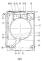
- the laundry washing machine shown in fig. 1 comprises a housing 10 and a tub 11 mounted therein and containing a rotatable drum 12 for the laundry.
- the housing 10 does not require any modifications with regard to the construction ofthe housings of washing machines actually on the market, and may correspond to the standardized dimensions of such housings.
- Drum 12 is rotatably mounted in tub 11 by means of fully conventional support and actuating elements which need not be described in detail.
- the tub 11 on the other hand is of a modified construction provided at its top with a chamber 13 enclosing electric resistance elements 14 and adapted to have the washing liquid 15 circulated therethrough.
- Chamber 13 is made of the same material as tub 11, for example stainless steel, and is preferably welded to the tub. Mounted at a central portion of chamber 13 corresponding to the highest point of tub 11 is at least one vertical pipe section 16 establishing free communication between chamber 13 and tub 11. Pipe section 16 acts as an overflow wall for the washing liquid supplied to chamber 13 to flow thereover and into tub 11, penetrating the perforations formed in the peripheral wall of drum 12 to thereby soak the laundry contained therein.
- the bottom portion of tub 11 is formed with an opening 17 communicating through a conduit 18 with a discharge pump 19 operable at the end of each washing cycle to discharge the washing liquid through a discharge pipe 20.
- a further conduit 21 connects discharge pump 19 to a recirculation pump 22 operable to deliver the washing liquid to chamber 13 via a recirculation conduit 23.
- An end portion 24 of recirculation conduit 23 extedns downwards into chamber 13 to a location adjacent its bottom to act as a syphon for evacuating the washing liquid from chamber 13 when pump 22 is stopped.
- This particular construction permits chamber 13 to be always kept clean, avoiding stagnant water remaining therein, and in particular the formation of deposits of loose fibers and of incrust ations of minerals which might otherwise impair the performance of the electric resistance elements 14.
- the machine of fig. 1 is also provided with a suitable detergent distributor 25 disposed in an upper portion of housing 10 and connected to tub 11 through a hose 26. Mains water is supplied to the machine in the conventional manner through detergent distributor 25.
- the machine shown in fig. 2 is a modification of the one shown in fig. 1 and operates on the same principle.
- This modification which offers the possibility of further structural and functional simplification, substantially consists in the employ of a single pump 35 for the recirculation and discharge of the washing liquid.
- a switch valve 36 operable to alternatively direct the flow of the washing liquid into receptacle 13 or through discharge conduit 20.
- a laundry washing machine of the type described may advantageously be provided with a laundry drying system so as to offer a complete treatment cycle.
- fig. 3 shows a combined laundry washing and drying machine in which the washing and drying functions are integrally provided thanks to the employ of the particular recirculation washing system including a receptacle housing the electric resistance heater elements.
- the machine shown in fig. 3 corresponds to the one shown in fig. 1, similar or identical components of the two embodiments being designated by the same referecne numerals.
- the modification consists in the provision of a drying air circulation system.
- the bottom opening 17 of tub 11 is additionally connected through a conduit 27 to a blower 28 disposed in an upper portion of housing 10 and connected to chamber 13 through a conduit 29.
- Chamber 13 is preferably provided with a further conduit 30 communicating it to tub 11.
- the washing system thus comprises tub 11, discharge pump 19, recirculation pump 22 and chamber 13, while the drying system includes tub 11, blower 28 and chamber 13.
- the electric resistance elements 14 are used for heating both the washing liquid and the drying air.
- a spray nozzle 31 connected to the water supply system of the machine is suitably inserted into intake conduit 27 of blower 28 for the injection of a water spray effective to condense the steam extracetd from the laundry.
- the condensate flows down through conduit 27 towards the bottom of tub 11 and is discharged by discharge pump 19.
- the described solution as a whole permits a combined laundry washing and drying machine to be simplified and rationalized to thereby adapt it to domestic use with considerable savings of waetr, detergents and energy in both the washing cycle and the drying cycle.
- fig. 4 shows a modification of the laundry washing machine of fig. 2 including a laundry drying function. Also in this case similar or identical components of the two embodiments are designated by the same reference numerals. A detailed description of the machine shown in fig. 4 does therefore not appear necessary, representing as it does a combination of the various components already described.
- the laundry washing machine embodies an effective and efficient integration of the washing liquid recirculation and heating functions in a machine operating on the principle of washing the laundry by sprinkling and thereby soaking it.
- the container 13 secured to the top of the tub 11 and containing the resistance elements 14 ensures a highly efficient heating of the washing liquid immediately prior to its being supplied to the laundry to thereby substantially preclude any heat losses. This solution thus results in a further reduction of the consumption of energy and ensures improved protection of the heater elements.
- the laundry washing machine according to the invention may in addition be advantageously combined with a laundry drying system of extremely simple construction not requiring any important modification of the laundry washing machine as a whole.
- the described laundry washing machine may of course be of the front-loading or of the top-loading type without requiring the construction and dimensions of the respective types of machines to be altered, so that the machine continues to conform to the various standards and existing regulations.
Landscapes
- Engineering & Computer Science (AREA)
- Textile Engineering (AREA)
- Detail Structures Of Washing Machines And Dryers (AREA)
Abstract
Description
- The present invention relates to an electric household appliance for washing and drying laundry, in which the washing liquid is recirculated in a laundering tub for soaking the laundry to thereby execute the washing process with considerable savings of water, detergents and energy.
- A laundry washing machine operating on this principle but likewise capable of executing conventional washing cycles with immersion of the laundry is described in European Patent Application No. 0146719. The laundry washing machine according to the named European patent allication is provided with a washing liquid collecting receptacle connected to a lower portion of the laundering tub and containing electric resistance elements for heating the washing liquid. A pump is operable to withdraw the washing liquid from the collecting receptacle and to deliver it via a suitable conduit to a top portion of the tub for sprinkling and soaking the laundry contained in a rotatable drum mounted in the tub.
- Although the solution described in the above named European patent application operates in a satisfactory manner, its construction can be improved with regard to the water supply and circulation system, and could suitably be provided in addition with a laundry drying system so as to permit a complete laundry treatment cycle to be carried out. As a matter of fact the arrangement of the washing liquid collecting receptacle in the lower portion of the machine presents considerable mounting problems in view of the restricetd space available within the reduced dimensions of a domestic laundry washing machine. In addition this construction requires the use of filtering and control devices for avoiding the accumulation of loose fibres and the formation of mineral incrustations in the collecting receptacle endangering the electric heater elements. It would therefore be preferable to place the collecting receptacle in a top portion of the machine. A solution of this type has been proposed in German Patent 234,908 filed long ago in 1910. According to this patent, however, the washing liquid collecting and heating receptacle is disposed outside of the machine, and the washing liquid is passed therethrough from top to bottom, returning into the tub through the hollow shaft of the drum. Apart from being rather complicated and bulky, and thus scarcely suitable for a machine to be installed in a domestic environment, this construction suffers from serious shortcomings.
- The machine operates with a high consumption of energy for sufficiently heating the washing liquid flowing continuously through the collecting receptacle in the absence of any shut-off valves between the latter and the tub. In addition the losses of hydraulic pressure along the connection conduits between the collecting receptacle and the tub result in a considerable reduction of the efficiency of the washing liquid jets ejected from sprinkler nozzles disposed around the drum containing the laundry. The described machine is finally not provided with any device for drying the laundry. Also known from more recent times are machines of the combined type in which the laundry is washed as well as dried. In these machines, however, the laundry is washed in the conventional manner by immersion in the washing liquid, and the washing and drying systems are usually separate, except for the use in certain cases of the mains water for condensing the steam generated by the drying process. Machines of this type are thus of an extremely complicated construction and rather uneconomical in operation. An example of a machine of this type is described in German Patent 2,529,577.
- The recent development of laundry washing machines with washing liquid recirculation, in which the heater elements are disposed outside of the laundering tub, offers the possibility of advantageously combining the laundry washing and drying functions in a single machine of simplifeid construction.
- It is therefore a main object of the present invention to propose a laundry washing machine of the washing liquid recirculation type, in which the functional components are of a simplified and more rational construction and adapted to be combined with additional components permitting the laundry to be also dried in the same machine.
- This object is attaiend in an electric household appliance for washing laundry, comprising a tub, a rotatable drum mounted in the tub for containing the laundry, and a washing liquid recirculation pump having an intake conduit and an outlet conduit connected respectively to a bottom portion and a top portion of the tub, electric resistance elements being provided for heating the washing liquid at a location exterior of the tub
- According to the invention, an electric household appliance of the above type is characterized by comprising a chamber mounted above the top of the tub and containing the electric resistance elements, the outlet conduit of the pump opening into this chamber, the latter communicating with the tub through a device acting as a washing liquid overflow wall. The laundry washing machine according to the invention may be integrally combined with a laundry drying system including a blower for the circulation of air through the tub; in this case the machine has as a further characteristic that the blower has an intake conduit connected to the bottom portion of the tub, and a delivery conduit opening into the chamber mounted above the top of the tub.
- Further objects and characteristics of the invention will become more clearly evident from the following description, given by way of example with reference to the accompanying drawings, wherein:
- fig. 1 and 2 show diagrammatic illustrations of washing machiens according to two embodiments of the invention, and
- figs. 3 and 4 show diagrammatic illustrations of combined laundry washing and drying machines according to two further embidiments of the invention.
- The laundry washing machine shown in fig. 1 comprises a
housing 10 and atub 11 mounted therein and containing arotatable drum 12 for the laundry. Thehousing 10 does not require any modifications with regard to the construction ofthe housings of washing machines actually on the market, and may correspond to the standardized dimensions of such housings.Drum 12 is rotatably mounted intub 11 by means of fully conventional support and actuating elements which need not be described in detail. Thetub 11 on the other hand is of a modified construction provided at its top with achamber 13 enclosingelectric resistance elements 14 and adapted to have thewashing liquid 15 circulated therethrough. -
Chamber 13 is made of the same material astub 11, for example stainless steel, and is preferably welded to the tub. Mounted at a central portion ofchamber 13 corresponding to the highest point oftub 11 is at least onevertical pipe section 16 establishing free communication betweenchamber 13 andtub 11.Pipe section 16 acts as an overflow wall for the washing liquid supplied tochamber 13 to flow thereover and intotub 11, penetrating the perforations formed in the peripheral wall ofdrum 12 to thereby soak the laundry contained therein. The bottom portion oftub 11 is formed with an opening 17 communicating through aconduit 18 with adischarge pump 19 operable at the end of each washing cycle to discharge the washing liquid through adischarge pipe 20. Afurther conduit 21 connectsdischarge pump 19 to arecirculation pump 22 operable to deliver the washing liquid tochamber 13 via arecirculation conduit 23. - An
end portion 24 of recirculation conduit 23 extedns downwards intochamber 13 to a location adjacent its bottom to act as a syphon for evacuating the washing liquid fromchamber 13 whenpump 22 is stopped. This particular construction permitschamber 13 to be always kept clean, avoiding stagnant water remaining therein, and in particular the formation of deposits of loose fibers and of incrust ations of minerals which might otherwise impair the performance of theelectric resistance elements 14. The machine of fig. 1 is also provided with asuitable detergent distributor 25 disposed in an upper portion ofhousing 10 and connected totub 11 through ahose 26. Mains water is supplied to the machine in the conventional manner throughdetergent distributor 25. - The machine shown in fig. 2 is a modification of the one shown in fig. 1 and operates on the same principle. This modification, which offers the possibility of further structural and functional simplification, substantially consists in the employ of a
single pump 35 for the recirculation and discharge of the washing liquid. To thispurpose recirculation conduit 23 is provided with aswitch valve 36 operable to alternatively direct the flow of the washing liquid intoreceptacle 13 or throughdischarge conduit 20. - All the remaining components of the machine shown in fig.2 correspond to those of the one shown in fig. 1 and are designated by the same referecne numerals, thus rendering a renewed description of these components dispensable. The machines diagrammatically illustrated in the two figures may of course be provided with any conventional components such as filters, pressure switches, a program control unit and the like, these components having been omitted for being not of particular interest in context with the invention.
- As already stated, a laundry washing machine of the type described may advantageously be provided with a laundry drying system so as to offer a complete treatment cycle. With this object in mind, fig. 3 shows a combined laundry washing and drying machine in which the washing and drying functions are integrally provided thanks to the employ of the particular recirculation washing system including a receptacle housing the electric resistance heater elements. As regards the liquid circulation system, the machine shown in fig. 3 corresponds to the one shown in fig. 1, similar or identical components of the two embodiments being designated by the same referecne numerals. The modification consists in the provision of a drying air circulation system. The bottom opening 17 of
tub 11 is additionally connected through aconduit 27 to ablower 28 disposed in an upper portion ofhousing 10 and connected tochamber 13 through aconduit 29.Chamber 13 is preferably provided with afurther conduit 30 communicating it totub 11. The laundry washing system and the drying system as well as the integral interconnection of the two are evident from the above description. The washing system thus comprisestub 11,discharge pump 19,recirculation pump 22 andchamber 13, while the drying system includestub 11,blower 28 andchamber 13. Theelectric resistance elements 14 are used for heating both the washing liquid and the drying air. It is finally noted that aspray nozzle 31 connected to the water supply system of the machine is suitably inserted intointake conduit 27 ofblower 28 for the injection of a water spray effective to condense the steam extracetd from the laundry. The condensate flows down throughconduit 27 towards the bottom oftub 11 and is discharged bydischarge pump 19. The described solution as a whole permits a combined laundry washing and drying machine to be simplified and rationalized to thereby adapt it to domestic use with considerable savings of waetr, detergents and energy in both the washing cycle and the drying cycle. - Analogous to what has been stated with reference to figs. 1 and 3, fig. 4 shows a modification of the laundry washing machine of fig. 2 including a laundry drying function. Also in this case similar or identical components of the two embodiments are designated by the same reference numerals. A detailed description of the machine shown in fig. 4 does therefore not appear necessary, representing as it does a combination of the various components already described.
- In conclusion, the laundry washing machine according to the invention embodies an effective and efficient integration of the washing liquid recirculation and heating functions in a machine operating on the principle of washing the laundry by sprinkling and thereby soaking it. The
container 13 secured to the top of thetub 11 and containing theresistance elements 14 ensures a highly efficient heating of the washing liquid immediately prior to its being supplied to the laundry to thereby substantially preclude any heat losses. This solution thus results in a further reduction of the consumption of energy and ensures improved protection of the heater elements. - The laundry washing machine according to the invention may in addition be advantageously combined with a laundry drying system of extremely simple construction not requiring any important modification of the laundry washing machine as a whole.
- The described laundry washing machine may of course be of the front-loading or of the top-loading type without requiring the construction and dimensions of the respective types of machines to be altered, so that the machine continues to conform to the various standards and existing regulations.
Claims (8)
Applications Claiming Priority (2)
| Application Number | Priority Date | Filing Date | Title |
|---|---|---|---|
| IT45718/86A IT1192075B (en) | 1986-04-09 | 1986-04-09 | HOUSEHOLD APPLIANCE MACHINE FOR LAUNDRY WASHING AND DRYING |
| IT4571886 | 1986-04-09 |
Publications (2)
| Publication Number | Publication Date |
|---|---|
| EP0240910A2 true EP0240910A2 (en) | 1987-10-14 |
| EP0240910A3 EP0240910A3 (en) | 1988-06-15 |
Family
ID=11257640
Family Applications (1)
| Application Number | Title | Priority Date | Filing Date |
|---|---|---|---|
| EP87104749A Withdrawn EP0240910A3 (en) | 1986-04-09 | 1987-03-31 | Electric household appliance for washing and drying laundry |
Country Status (3)
| Country | Link |
|---|---|
| US (1) | US4757699A (en) |
| EP (1) | EP0240910A3 (en) |
| IT (1) | IT1192075B (en) |
Cited By (7)
| Publication number | Priority date | Publication date | Assignee | Title |
|---|---|---|---|---|
| EP0344549A1 (en) * | 1988-05-30 | 1989-12-06 | INDUSTRIE ZANUSSI S.p.A. | Heating apparatus for combined clothes washing and drying machine |
| GB2291891A (en) * | 1994-10-13 | 1996-02-07 | Bosch Siemens Hausgeraete | Washing machine equipped for drying |
| WO2006009364A1 (en) * | 2004-07-20 | 2006-01-26 | Lg Electronics Inc. | Washing machine and method for controlling the same |
| CN100453728C (en) * | 2003-12-23 | 2009-01-21 | 三星电子株式会社 | Drum type washing machine and method of use thereof |
| CN101184883B (en) * | 2004-07-20 | 2010-09-22 | Lg电子株式会社 | Washing machine and control method thereof |
| WO2014044531A1 (en) * | 2012-09-24 | 2014-03-27 | Arcelik Anonim Sirketi | A laundry washing and drying machine comprising a condenser |
| ITPR20130110A1 (en) * | 2013-12-30 | 2015-07-01 | Indesit Co Spa | APPLIANCES AND WASHING AND DRYING METHOD OF CLOTHS. |
Families Citing this family (21)
| Publication number | Priority date | Publication date | Assignee | Title |
|---|---|---|---|---|
| GB2228308A (en) * | 1989-02-17 | 1990-08-22 | Servis Group Limited | Drying machine with water spray condenser |
| KR0133277Y1 (en) * | 1995-12-30 | 1999-04-15 | 배순훈 | Bottom Blow Dryer |
| ES2152142B1 (en) * | 1998-02-02 | 2001-08-01 | Balay Sa | ADDITIVE CONTRIBUTION SYSTEM TO WASHING-DRYING MACHINES. |
| US6006445A (en) * | 1998-09-03 | 1999-12-28 | Large; Ronald D. | Washer/dryer combination |
| US6269667B1 (en) * | 1998-09-22 | 2001-08-07 | Mainstream Engineering Corporation | Clothes washer and dryer system for recycling and reusing gray water |
| DE10044030B4 (en) * | 2000-09-06 | 2004-01-29 | Miele & Cie. Kg | Clothes dryer with a condensation device |
| US20040083772A1 (en) * | 2002-11-04 | 2004-05-06 | Gaines Jeffrey L. | Washer dryer machine |
| US20050112244A1 (en) * | 2003-11-26 | 2005-05-26 | Hall Alex F. | Container having separate cells for protection and display of produce |
| US20090126088A1 (en) * | 2007-08-14 | 2009-05-21 | Yadav Sudhansu S | Protective garment for use with radiation monitoring devices |
| US20090173048A1 (en) * | 2004-03-11 | 2009-07-09 | Quest Environmental & Safety Products, Inc. | Packaged non-woven garments |
| US20050198926A1 (en) * | 2004-03-11 | 2005-09-15 | Yadav Sudhansu S. | Method and apparatus for packaging non-woven garments |
| ES2322774T3 (en) * | 2006-02-21 | 2009-06-26 | Electrolux Home Products Corporation N.V. | DOMESTIC CLOTHES DRYING MACHINE WITH ADDITIONAL CONDENSER. |
| DE102008021376A1 (en) * | 2008-04-29 | 2009-11-05 | BSH Bosch und Siemens Hausgeräte GmbH | Exhaust air dryer with back-air detection and method for its operation |
| IT1392256B1 (en) * | 2008-12-05 | 2012-02-22 | Illinois Tool Works | PRESSURE SENSOR MODIFIED TO DETECT OPERATIONAL PARAMETERS OF A APPLIANCE EQUIPPED WITH A RELATIVELY MOBILE COMPONENT |
| US20100257661A1 (en) * | 2009-04-13 | 2010-10-14 | Yadav Sudhansu S | Disposable safety garment with reduced particulate shedding |
| US8166591B2 (en) | 2010-12-09 | 2012-05-01 | General Electric Company | Apparatus and method for wash fluid recirculation in a washing machine |
| US20130255331A1 (en) * | 2012-03-27 | 2013-10-03 | Bsh Bosch Und Siemens Hausgerate Gmbh | Clothes treatment appliance with water container and downpipe |
| US20130255094A1 (en) * | 2012-03-27 | 2013-10-03 | Bsh Bosch Und Siemens Hausgerate Gmbh | Clothes treatment appliance with water container and a transfer pipe |
| ITTO20120598A1 (en) * | 2012-07-06 | 2014-01-07 | Illinois Tool Works | HEATING DEVICE FOR HOUSEHOLD APPLIANCES WITH OPTICAL LIQUID LEVEL SENSOR |
| US20170241066A1 (en) * | 2014-11-02 | 2017-08-24 | Nicholas Caspers | Laundry appliance that identifies items not intended to be run through a washer or dryer cycle |
| CN106087357B (en) * | 2016-06-27 | 2018-05-01 | 江苏科技大学 | A kind of dryer peculiar to vessel and control method |
Family Cites Families (13)
| Publication number | Priority date | Publication date | Assignee | Title |
|---|---|---|---|---|
| DE234908C (en) * | ||||
| CH124712A (en) * | 1926-03-15 | 1928-04-02 | Siemens Elektrowaerme Gmbh | Hot water storage tank designed as a drain storage tank with electrical heating. |
| DE743562C (en) * | 1940-12-10 | 1953-08-31 | Siemens Schuckertwerke A G Ber | Washing machine |
| FR951379A (en) * | 1947-01-16 | 1949-10-24 | Johnson Aircraft Components Lt | Washing machine and dryer |
| CH282059A (en) * | 1950-03-10 | 1952-04-15 | Usines Jean Gallay Sa D | Washing and wringing machine. |
| CH324164A (en) * | 1953-03-26 | 1957-09-15 | Peter Pfenningsberg Gmbh Masch | Automatic washing machine and spin dryer |
| US2887862A (en) * | 1958-03-24 | 1959-05-26 | Gen Electric | Material dispensing system for combination clothes washing and drying machines |
| ES432739A1 (en) * | 1974-11-30 | 1976-12-01 | Marchiselli Tognoli | Washing machine |
| DE2529577C3 (en) * | 1975-07-02 | 1979-09-27 | August Lepper Maschinen- U. Apparatebau Gmbh, 5340 Bad Honnef | Drum washing and drying machine |
| DE2852449C2 (en) * | 1978-12-04 | 1982-03-04 | August Lepper Maschinen- U. Apparatebau Gmbh, 5340 Bad Honnef | Drum washing and drying machine |
| ES242354Y (en) * | 1979-03-16 | 1979-11-16 | DRYING DEVICE FOR CLOTHES WASHING MACHINES. | |
| DE3017089A1 (en) * | 1980-05-03 | 1981-11-05 | Miele & Cie GmbH & Co, 4830 Gütersloh | WASHING TREATMENT MACHINE SET UP FOR WASHING, SPIN, AND DRYING |
| IT1174953B (en) * | 1983-12-06 | 1987-07-01 | Zanussi A Spa Industrie | WASHING MACHINE |
-
1986
- 1986-04-09 IT IT45718/86A patent/IT1192075B/en active
-
1987
- 1987-03-20 US US07/028,684 patent/US4757699A/en not_active Expired - Fee Related
- 1987-03-31 EP EP87104749A patent/EP0240910A3/en not_active Withdrawn
Cited By (11)
| Publication number | Priority date | Publication date | Assignee | Title |
|---|---|---|---|---|
| EP0344549A1 (en) * | 1988-05-30 | 1989-12-06 | INDUSTRIE ZANUSSI S.p.A. | Heating apparatus for combined clothes washing and drying machine |
| GB2291891A (en) * | 1994-10-13 | 1996-02-07 | Bosch Siemens Hausgeraete | Washing machine equipped for drying |
| GB2291891B (en) * | 1994-10-13 | 1996-07-03 | Bosch Siemens Hausgeraete | Washing machine equipped for drying |
| RU2144104C1 (en) * | 1994-10-13 | 2000-01-10 | Бош-Сименс Хаусгерете ГмбХ | Automatic washing machine intended for drying |
| CN100453728C (en) * | 2003-12-23 | 2009-01-21 | 三星电子株式会社 | Drum type washing machine and method of use thereof |
| WO2006009364A1 (en) * | 2004-07-20 | 2006-01-26 | Lg Electronics Inc. | Washing machine and method for controlling the same |
| CN101184883B (en) * | 2004-07-20 | 2010-09-22 | Lg电子株式会社 | Washing machine and control method thereof |
| US8122547B2 (en) | 2004-07-20 | 2012-02-28 | Lg Electronics Inc. | Washing machine and method for controlling the same |
| WO2014044531A1 (en) * | 2012-09-24 | 2014-03-27 | Arcelik Anonim Sirketi | A laundry washing and drying machine comprising a condenser |
| ITPR20130110A1 (en) * | 2013-12-30 | 2015-07-01 | Indesit Co Spa | APPLIANCES AND WASHING AND DRYING METHOD OF CLOTHS. |
| WO2015101873A1 (en) * | 2013-12-30 | 2015-07-09 | Indesit Company S.P.A. | Household appliance and method for washing and drying laundry |
Also Published As
| Publication number | Publication date |
|---|---|
| IT8645718A0 (en) | 1986-04-09 |
| EP0240910A3 (en) | 1988-06-15 |
| IT1192075B (en) | 1988-03-31 |
| US4757699A (en) | 1988-07-19 |
Similar Documents
| Publication | Publication Date | Title |
|---|---|---|
| EP0240910A2 (en) | Electric household appliance for washing and drying laundry | |
| US5606878A (en) | Clothes washing machine with improved water recovery tank | |
| EP1865099B1 (en) | Prevention of scale and sludge in a steam generator of a fabric treatment appliance | |
| EP0240911B1 (en) | Filter for a laundry washing machine | |
| EP2239364B1 (en) | Washing machine with an improved washing/rinsing-liquid inlet circuit | |
| EP1865101B1 (en) | Draining liquid from a steam generator of a fabric treatment appliance | |
| US5816273A (en) | Dishwashing machine with electric heating means | |
| EP0132884B1 (en) | Device for suppressing steam in domestic washing machines | |
| CN201169701Y (en) | Self-cleaning sterilization apparatus of washing machine | |
| EP0370552A1 (en) | Improved dishwasher | |
| CN104562542B (en) | Laundry treating machine | |
| CA1066078A (en) | Combination drain sump and air pressure chamber for automatic clothes washing machine | |
| EP0404253A1 (en) | Improved washing machine | |
| GB2244209A (en) | Dishwasher machine for pieces of small size | |
| EP0597509B1 (en) | A dynamic flow washing machine | |
| EP0552843B1 (en) | Washing and drying machine with an improved safety device against water pollution | |
| MX2008011099A (en) | Fabric treatment appliance with steam backflow device. | |
| EP2031117B1 (en) | Fabric treatment appliance with steam backflow device | |
| EP2535454B1 (en) | Washing machine | |
| EP0463576A1 (en) | Method and installation for the condensation of humidity in laundry washers | |
| EP2933367A1 (en) | Household washing appliance with steam generating means for external use | |
| EP2164379B1 (en) | Dish washing machine | |
| GB2190926A (en) | Washing liquid collector for clothes washing machines | |
| RU2051248C1 (en) | Washing machine | |
| EP0333251A2 (en) | Improved overflow system |
Legal Events
| Date | Code | Title | Description |
|---|---|---|---|
| PUAI | Public reference made under article 153(3) epc to a published international application that has entered the european phase |
Free format text: ORIGINAL CODE: 0009012 |
|
| AK | Designated contracting states |
Kind code of ref document: A2 Designated state(s): AT CH DE ES FR GB IT LI SE |
|
| RAP1 | Party data changed (applicant data changed or rights of an application transferred) |
Owner name: INDUSTRIE ZANUSSI S.P.A. |
|
| PUAL | Search report despatched |
Free format text: ORIGINAL CODE: 0009013 |
|
| AK | Designated contracting states |
Kind code of ref document: A3 Designated state(s): AT CH DE ES FR GB IT LI SE |
|
| 17P | Request for examination filed |
Effective date: 19881019 |
|
| 17Q | First examination report despatched |
Effective date: 19900411 |
|
| ITF | It: translation for a ep patent filed | ||
| STAA | Information on the status of an ep patent application or granted ep patent |
Free format text: STATUS: THE APPLICATION IS DEEMED TO BE WITHDRAWN |
|
| 18D | Application deemed to be withdrawn |
Effective date: 19910502 |
|
| RIN1 | Information on inventor provided before grant (corrected) |
Inventor name: DURAZZANI, PIERO Inventor name: ARREGHINI, LUIGI |
|
| P01 | Opt-out of the competence of the unified patent court (upc) registered |
Effective date: 20230309 |