EP0240774A2 - Dispositif pour refroidir un détecteur, en particulier pour un traceur optique - Google Patents
Dispositif pour refroidir un détecteur, en particulier pour un traceur optique Download PDFInfo
- Publication number
- EP0240774A2 EP0240774A2 EP87103743A EP87103743A EP0240774A2 EP 0240774 A2 EP0240774 A2 EP 0240774A2 EP 87103743 A EP87103743 A EP 87103743A EP 87103743 A EP87103743 A EP 87103743A EP 0240774 A2 EP0240774 A2 EP 0240774A2
- Authority
- EP
- European Patent Office
- Prior art keywords
- molecular filter
- temperature
- state
- compressed gas
- compressor
- Prior art date
- Legal status (The legal status is an assumption and is not a legal conclusion. Google has not performed a legal analysis and makes no representation as to the accuracy of the status listed.)
- Granted
Links
- 238000001816 cooling Methods 0.000 title claims abstract description 18
- 230000003287 optical effect Effects 0.000 title claims abstract description 5
- 239000000700 radioactive tracer Substances 0.000 title 1
- 230000000694 effects Effects 0.000 claims abstract description 8
- 230000002452 interceptive effect Effects 0.000 claims description 4
- 239000000470 constituent Substances 0.000 claims description 3
- 230000001105 regulatory effect Effects 0.000 claims description 3
- 238000010438 heat treatment Methods 0.000 claims 1
- 230000008929 regeneration Effects 0.000 abstract description 4
- 238000011069 regeneration method Methods 0.000 abstract description 4
- 239000007789 gas Substances 0.000 description 56
- OKTJSMMVPCPJKN-UHFFFAOYSA-N Carbon Chemical compound [C] OKTJSMMVPCPJKN-UHFFFAOYSA-N 0.000 description 8
- 238000001179 sorption measurement Methods 0.000 description 6
- 238000003795 desorption Methods 0.000 description 4
- CURLTUGMZLYLDI-UHFFFAOYSA-N Carbon dioxide Chemical compound O=C=O CURLTUGMZLYLDI-UHFFFAOYSA-N 0.000 description 2
- 238000011001 backwashing Methods 0.000 description 2
- 229920006395 saturated elastomer Polymers 0.000 description 2
- 230000007704 transition Effects 0.000 description 2
- 238000011144 upstream manufacturing Methods 0.000 description 2
- 238000013459 approach Methods 0.000 description 1
- 229910002092 carbon dioxide Inorganic materials 0.000 description 1
- 239000001569 carbon dioxide Substances 0.000 description 1
- 230000001419 dependent effect Effects 0.000 description 1
- 238000010586 diagram Methods 0.000 description 1
- 230000002349 favourable effect Effects 0.000 description 1
- 238000002955 isolation Methods 0.000 description 1
- 230000007257 malfunction Effects 0.000 description 1
- 239000000463 material Substances 0.000 description 1
- 238000000034 method Methods 0.000 description 1
- 239000002244 precipitate Substances 0.000 description 1
- XLYOFNOQVPJJNP-UHFFFAOYSA-N water Chemical compound O XLYOFNOQVPJJNP-UHFFFAOYSA-N 0.000 description 1
Images

Classifications
-
- F—MECHANICAL ENGINEERING; LIGHTING; HEATING; WEAPONS; BLASTING
- F25—REFRIGERATION OR COOLING; COMBINED HEATING AND REFRIGERATION SYSTEMS; HEAT PUMP SYSTEMS; MANUFACTURE OR STORAGE OF ICE; LIQUEFACTION SOLIDIFICATION OF GASES
- F25B—REFRIGERATION MACHINES, PLANTS OR SYSTEMS; COMBINED HEATING AND REFRIGERATION SYSTEMS; HEAT PUMP SYSTEMS
- F25B9/00—Compression machines, plants or systems, in which the refrigerant is air or other gas of low boiling point
- F25B9/02—Compression machines, plants or systems, in which the refrigerant is air or other gas of low boiling point using Joule-Thompson effect; using vortex effect
-
- G—PHYSICS
- G01—MEASURING; TESTING
- G01J—MEASUREMENT OF INTENSITY, VELOCITY, SPECTRAL CONTENT, POLARISATION, PHASE OR PULSE CHARACTERISTICS OF INFRARED, VISIBLE OR ULTRAVIOLET LIGHT; COLORIMETRY; RADIATION PYROMETRY
- G01J5/00—Radiation pyrometry, e.g. infrared or optical thermometry
- G01J5/02—Constructional details
- G01J5/06—Arrangements for eliminating effects of disturbing radiation; Arrangements for compensating changes in sensitivity
- G01J5/061—Arrangements for eliminating effects of disturbing radiation; Arrangements for compensating changes in sensitivity by controlling the temperature of the apparatus or parts thereof, e.g. using cooling means or thermostats
Definitions
- the gas in the gas bottles is pure.
- the sucked-in air contains gaseous components that condense or freeze at comparatively high temperatures, for example water vapor or carbon dioxide. Such components of the air would condense or freeze in the area of the cooled detector and thereby the Make the cooling system inoperable in a short time, for example by clogging the compressed gas line or the outlet nozzle, via which the expansion of the compressed air takes place.
- the problem has only been postponed: Instead of changing the gas bottle, it is now necessary to change the molecular filter. Failure to do so may also cause the viewfinder to malfunction at the wrong time. When the molecular filter is saturated, it no longer adsorbs the interfering components. As described, these can then precipitate and freeze in the area of the cooled detector.
- the invention has for its object to design a device of the type mentioned so that the need to replace parts is eliminated.
- Another, more specific object of the invention is to enable the use of the smallest possible molecular filter.
- the storage container is "charged", ie filled with compressed gas under the pressure prevailing downstream of the molecular filter.
- the compressed gas line downstream of the connection of the storage container is then shut off and at the same time an outlet upstream of the molecular filter is opened. Gas now flows backwards from the storage container through the molecular filter to the outlet. While adsorption on the molecular filter takes place at a temperature and pressure, namely the outlet pressure of the compressor, which is low relative to the backwash temperature, backwashing is carried out with a temperature of the molecular filter which is high relative to the normal working temperature and a low pressure, namely the outlet pressure. The low temperature and the high pressure favor the adsorption.
- the high temperature and the low pressure promote the expulsion of the adsorbed components during backwashing.
- the amount of gas stored in the storage container is sufficient to remove the adsorbed constituents from the molecular filter again and to make it functional for normal cooling operation.
- This arrangement is suitable for continuous operation. There is no need to replace gas cylinders or molecular filters on a regular basis as in the previous proposals.
- the molecular filter can be designed to save space because it is regenerated before saturation occurs.
- Embodiments of the invention are the subject of the dependent claims.
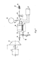
- a compressor 10 is driven by a motor 12.
- the compressor 10 supplies an output pressure which is effective in a compressed gas line 16 via a check valve 14.
- a molecular filter 18 is connected downstream of the compressor 10 in the compressed gas line 16.
- the molecular filter 18 can contain activated carbon, for example.
- One gram of activated carbon has a surface area of around 500 m2.
- the compressed gas line then leads via a controlled valve 20 to a cooling device 22 for a detector 24.
- the cooling device 22 uses the Joule-Thomson effect.
- the compressed gas is released through a nozzle and cools down.
- the relaxed and cooled gas flows over a heat exchanger located in the compressed gas line 16, so that the inflowing compressed gas is pre-cooled.
- the cooling device 22 is known per se and is therefore not shown and described in detail here. A very strong cooling of the detector 24 is thus achieved. At the low temperatures that occur, certain components of the sucked-in air can freeze out and thus render the cooling device 22 inoperable. To avoid
- a branch line 28 branches off from the compressed gas line 16 at a connection 26.
- the branch line 28 leads to a storage container 30.
- An adjustable throttle 32 is arranged in the branch line.
- a branch line 34 branches off from the compressed gas line 16.
- the branch line 34 contains a controlled valve 36 and is connected to an outlet via a check valve 37 opening in the outlet direction.
- the molecular filter 18 is via temperature control means in the form of Peltier elements 38 with a heat accumulator 40, i.e. a mass with a fairly large heat capacity.
- the housings of the compressor 10 and the motor 12 (or one of these) are preferably used as the heat accumulator 40.
- the controlled valves 20 and 36 and the Peltier elements 38 are controlled by a control device 42.
- the controlled valve 36 can be controlled in a first state, the controlled valve 20 can be controlled and the temperature-controlling means can be switched to the relatively low temperature, ie the Peltier elements 38 are flowed through in such a way that they extract heat from the molecular filter 18 and feed the heat accumulator 40.
- This is the normal operation of the device in which the cooling device 22 is in operation and the molecular filter 18 is kept at a low temperature in order to adsorb as much of the components of the compressed gas to be eliminated as possible.
- the controlled valve 36 can be opened, and the controlled valve 20 can be closed the temperature control means switchable to a relatively high temperature. Current then flows through the Peltier elements 38 such that the molecular filter 18 is heated.
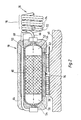
- the molecular filter 18 includes an elongated housing 50 having an inlet 52 at one end and an outlet 54 at the other end. At said one end an inlet chamber 56 is formed, into which the inlet 52 opens. At the other end, an outlet chamber 58 is formed from which the outlet extends. Between the inlet chamber 56 and outlet chamber 58, a filter insert 60 is arranged in the housing 50, which consists for example of activated carbon.
- the housing 50 is seated in a holding jacket 62, which ensures good heat conduction and distribution.
- the holding jacket 62 is seated via the Peltier elements 38 on the housing of the compressor 10 serving as a heat accumulator 40. Outside the area of the Peltier elements 32, the housing 50 and the holding jacket 62 are surrounded by a heat-insulating jacket 64.
- the pressure line 16 is connected to a section 66 on the compressor side with the inlet 52 and to a section 68 leading to the cooling device 22 with the outlet 54.
- the section 68 is guided through the insulating jacket 64 and the holding jacket 62 to the inlet side.
- the gas flowing in to the molecular filter 18 via section 66 is in heat exchange with the gas flowing out of the molecular filter 18 via section 68 through a countercurrent heat exchanger 70.
- the countercurrent heat exchanger 70 has tubes 72 for the inflowing gas, some of which of section 66 of pressure line 16, and pipes 74 for the outflowing gas, which form part of section 68 of pressure line 16.
- the tubes 72 and 74 are in close thermal contact with one another and are helically coiled together.
- the helically coiled tubes 72 and 74 act like a coil spring and are thus resilient in the axial direction.
- the molecular filter 18 is largely relieved of axial forces that could act via the compressed gas line 16.
- a temperature sensor 76 is attached to the molecular filter 18.
- the temperature sensor 76 applies a temperature signal to the control device 42.
- a temperature control can then be carried out in that the control device 42 contains a controller by means of which the temperature of the molecular filter 18 by means of the temperature-controlling means, i.e. of the Peltier elements 32, can be regulated to the relatively low temperature in the first state and to the relatively high temperature in the second state. Adsorption and desorption are then carried out at defined, regulated temperatures.
- Compressed gas 10 supplies compressed gas (compressed air) to the cooling device 22 via the compressed gas line 16 given and thus the detector 24 is strongly cooled. Unwanted components of this compressed gas are filtered out by adsorption through the molecular filter 18. As can be seen from FIG. 3, the higher the pressure and the lower the temperature, the more a certain amount of filter material such as activated carbon can absorb such components until saturation. Therefore, in normal operation, the molecular filter 18 is cooled by the Peltier elements 38. The pressure is the outlet pressure of the compressor 10 and is therefore relatively high. Both are favorable for adsorption. The effect is further improved and the transition to the low temperature is accelerated in that the compressed gas supplied to the molecular filter 18 is pre-cooled in the countercurrent heat exchanger 70 by the compressed gas flowing out of it.
- the storage container 30 is "charged", i.e. filled with compressed gas under the pressure supplied by the compressor 10 and prevailing in the compressed gas line.
- the regeneration of the molecular filter 18 is initiated by the control device. This can be done at fixed time intervals based on empirical values.
- the control device 42 then changes to the second state.
- the controlled valve 20 is closed, the controlled valve 36 is opened and the compressor 10 is switched off.
- the molecular filter 18 is heated by the Peltier elements 38.
- a flow of compressed gas flows from the storage container 30 via the throttle 32 in the opposite direction through the molecular filter 18 and via the branch line 34 to the outlet.
- the flow rate can be selected appropriately by the throttle 32.
- This flow causes the gas components adsorbed in the molecular filter 18 to be desorbed, which are then led to the outlet.
- the desorption rate i.e. the amount of gas desorbed from a given flow per unit of time, the higher the temperature and the lower the pressure.
- the desorption and thus the regeneration of the molecular filter 18 can thus take place in a time that is short compared to the time of normal operation.
- the effect is improved and the transition is accelerated by preheating the gas flowing to the molecular filter now via pipe 72 through the gas now flowing through pipe 74. It has been shown that the amount of gas stored in the storage container 30 is sufficient for the regeneration of the molecular filter 18.
Applications Claiming Priority (2)
| Application Number | Priority Date | Filing Date | Title |
|---|---|---|---|
| DE3611206 | 1986-04-04 | ||
| DE19863611206 DE3611206A1 (de) | 1986-04-04 | 1986-04-04 | Vorrichtung zum kuehlen eines detektors, insbesondere bei einem optischen sucher |
Publications (3)
| Publication Number | Publication Date |
|---|---|
| EP0240774A2 true EP0240774A2 (fr) | 1987-10-14 |
| EP0240774A3 EP0240774A3 (en) | 1990-03-07 |
| EP0240774B1 EP0240774B1 (fr) | 1991-09-11 |
Family
ID=6297855
Family Applications (1)
| Application Number | Title | Priority Date | Filing Date |
|---|---|---|---|
| EP87103743A Expired - Lifetime EP0240774B1 (fr) | 1986-04-04 | 1987-03-14 | Dispositif pour refroidir un détecteur, en particulier pour un traceur optique |
Country Status (3)
| Country | Link |
|---|---|
| US (1) | US4750338A (fr) |
| EP (1) | EP0240774B1 (fr) |
| DE (2) | DE3611206A1 (fr) |
Cited By (1)
| Publication number | Priority date | Publication date | Assignee | Title |
|---|---|---|---|---|
| EP1920983A2 (fr) * | 2006-11-09 | 2008-05-14 | Bendix Commercial Vehicle Systems LLC | Testeur de durée de vie d'une cartouche |
Families Citing this family (18)
| Publication number | Priority date | Publication date | Assignee | Title |
|---|---|---|---|---|
| DE4131529C2 (de) * | 1991-09-21 | 1994-03-31 | Bodenseewerk Geraetetech | Einrichtung zur Freigabe der Kühlmittelzufuhr in einem Flugkörper |
| DE4226024C1 (fr) * | 1992-08-06 | 1993-07-15 | Bodenseewerk Geraetetechnik Gmbh, 7770 Ueberlingen, De | |
| US5551244A (en) * | 1994-11-18 | 1996-09-03 | Martin Marietta Corporation | Hybrid thermoelectric/Joule-Thomson cryostat for cooling detectors |
| US5606870A (en) * | 1995-02-10 | 1997-03-04 | Redstone Engineering | Low-temperature refrigeration system with precise temperature control |
| GB9505915D0 (en) * | 1995-03-23 | 1995-05-10 | Ultra Electronics Ltd | Cooler |
| GB9506652D0 (en) * | 1995-03-31 | 1995-05-24 | Cryogenic Technology Ltd | Supplying liquid cryogen to cryosurgical apparatus |
| DE19733455B4 (de) * | 1997-08-02 | 2012-03-29 | Curamik Electronics Gmbh | Wärmetauscheranordnung sowie Kühlsystem mit wenigstens einer derartigen Wärmetauscheranordnung |
| DE19823996A1 (de) * | 1998-05-28 | 1999-12-02 | Siemens Ag | Verdichteraggregat mit Kühlvorrichtung |
| US20070101737A1 (en) * | 2005-11-09 | 2007-05-10 | Masao Akei | Refrigeration system including thermoelectric heat recovery and actuation |
| US20090241592A1 (en) * | 2007-10-05 | 2009-10-01 | Emerson Climate Technologies, Inc. | Compressor assembly having electronics cooling system and method |
| US8950206B2 (en) * | 2007-10-05 | 2015-02-10 | Emerson Climate Technologies, Inc. | Compressor assembly having electronics cooling system and method |
| US7895003B2 (en) | 2007-10-05 | 2011-02-22 | Emerson Climate Technologies, Inc. | Vibration protection in a variable speed compressor |
| US9541907B2 (en) | 2007-10-08 | 2017-01-10 | Emerson Climate Technologies, Inc. | System and method for calibrating parameters for a refrigeration system with a variable speed compressor |
| US8459053B2 (en) * | 2007-10-08 | 2013-06-11 | Emerson Climate Technologies, Inc. | Variable speed compressor protection system and method |
| US8418483B2 (en) * | 2007-10-08 | 2013-04-16 | Emerson Climate Technologies, Inc. | System and method for calculating parameters for a refrigeration system with a variable speed compressor |
| US8539786B2 (en) | 2007-10-08 | 2013-09-24 | Emerson Climate Technologies, Inc. | System and method for monitoring overheat of a compressor |
| US8448459B2 (en) * | 2007-10-08 | 2013-05-28 | Emerson Climate Technologies, Inc. | System and method for evaluating parameters for a refrigeration system with a variable speed compressor |
| US11206743B2 (en) | 2019-07-25 | 2021-12-21 | Emerson Climate Technolgies, Inc. | Electronics enclosure with heat-transfer element |
Citations (6)
| Publication number | Priority date | Publication date | Assignee | Title |
|---|---|---|---|---|
| US3413819A (en) * | 1966-05-09 | 1968-12-03 | Hughes Aircraft Co | Flow rate control for a joule-thomson refrigerator |
| US4080802A (en) * | 1976-07-14 | 1978-03-28 | International Telephone And Telegraph Corporation | Hybrid gas cryogenic cooler |
| DE3106469A1 (de) * | 1981-02-21 | 1982-09-09 | Herbert Dr.-Ing. 5963 Wenden Brandt | Steuereinrichtung fuer den spuelluftverbrauch bei der regeneration des adsorptionsmittels in einer vorrichtung zur erzeugung trockener druckluft |
| EP0093253A1 (fr) * | 1982-05-05 | 1983-11-09 | Knorr-Bremse Ag | Dispositif de commande pour la régénération d'un sécheur d'air pour un dispositif pneumatique, en particulier un dispositif de freinage pour véhicules |
| DE8405789U1 (de) * | 1984-02-25 | 1985-06-20 | Robert Bosch Gmbh, 7000 Stuttgart | Lufttrockner |
| EP0239375A2 (fr) * | 1986-03-24 | 1987-09-30 | British Aerospace Public Limited Company | Dispositif d'alimentation en fluide décontaminé et systèmes cryogéniques utilisant un tel dispositif |
Family Cites Families (3)
| Publication number | Priority date | Publication date | Assignee | Title |
|---|---|---|---|---|
| US3225517A (en) * | 1963-01-22 | 1965-12-28 | Joy Mfg Co | Gas drying method |
| GB1125437A (en) * | 1964-12-11 | 1968-08-28 | English Electric Co Ltd | Improvements in electrical transformers and reactors |
| US3488971A (en) * | 1968-04-29 | 1970-01-13 | Gershon Meckler | Comfort conditioning system |
-
1986
- 1986-04-04 DE DE19863611206 patent/DE3611206A1/de not_active Ceased
-
1987
- 1987-03-14 DE DE8787103743T patent/DE3772806D1/de not_active Expired - Fee Related
- 1987-03-14 EP EP87103743A patent/EP0240774B1/fr not_active Expired - Lifetime
- 1987-04-02 US US07/034,104 patent/US4750338A/en not_active Expired - Fee Related
Patent Citations (6)
| Publication number | Priority date | Publication date | Assignee | Title |
|---|---|---|---|---|
| US3413819A (en) * | 1966-05-09 | 1968-12-03 | Hughes Aircraft Co | Flow rate control for a joule-thomson refrigerator |
| US4080802A (en) * | 1976-07-14 | 1978-03-28 | International Telephone And Telegraph Corporation | Hybrid gas cryogenic cooler |
| DE3106469A1 (de) * | 1981-02-21 | 1982-09-09 | Herbert Dr.-Ing. 5963 Wenden Brandt | Steuereinrichtung fuer den spuelluftverbrauch bei der regeneration des adsorptionsmittels in einer vorrichtung zur erzeugung trockener druckluft |
| EP0093253A1 (fr) * | 1982-05-05 | 1983-11-09 | Knorr-Bremse Ag | Dispositif de commande pour la régénération d'un sécheur d'air pour un dispositif pneumatique, en particulier un dispositif de freinage pour véhicules |
| DE8405789U1 (de) * | 1984-02-25 | 1985-06-20 | Robert Bosch Gmbh, 7000 Stuttgart | Lufttrockner |
| EP0239375A2 (fr) * | 1986-03-24 | 1987-09-30 | British Aerospace Public Limited Company | Dispositif d'alimentation en fluide décontaminé et systèmes cryogéniques utilisant un tel dispositif |
Non-Patent Citations (1)
| Title |
|---|
| BERICHTE AUS TECHNIK UND WISSENSCHAFT, Nr. 57, Seiten 48-51, Wiesbaden, DE; W. ROHDE: "20 Jahre Erfahrung mit Molekularsieben im Luftzerlegungsanlagenbau" * |
Cited By (2)
| Publication number | Priority date | Publication date | Assignee | Title |
|---|---|---|---|---|
| EP1920983A2 (fr) * | 2006-11-09 | 2008-05-14 | Bendix Commercial Vehicle Systems LLC | Testeur de durée de vie d'une cartouche |
| EP1920983A3 (fr) * | 2006-11-09 | 2009-04-22 | Bendix Commercial Vehicle Systems LLC | Testeur de durée de vie d'une cartouche |
Also Published As
| Publication number | Publication date |
|---|---|
| DE3611206A1 (de) | 1987-10-08 |
| EP0240774A3 (en) | 1990-03-07 |
| DE3772806D1 (de) | 1991-10-17 |
| US4750338A (en) | 1988-06-14 |
| EP0240774B1 (fr) | 1991-09-11 |
Similar Documents
| Publication | Publication Date | Title |
|---|---|---|
| EP0240774B1 (fr) | Dispositif pour refroidir un détecteur, en particulier pour un traceur optique | |
| DE3808653C2 (de) | Verfahren zum Betrieb einer Adsorptionskälteanlage | |
| EP0003964B1 (fr) | Procédé et installation d'extraction d'eau à partir de l'humidité atmosphérique | |
| DE2500303C3 (de) | Kühlanlage | |
| EP0477481B1 (fr) | Filtre dans le courant d'arrivé d'air pour installation de chauffage ou de conditionnement d'air d'un véhicule automobile | |
| DE2532099B2 (de) | Verfahren zur Erhöhung der Reinstickstoff-Ausbeute bei kryogenen Lufttrennverfahren und Anordnung zum Ausüben dieses Verfahrens | |
| DE1619851B2 (de) | Vorrichtung zum trocknen von komprimiertem gas | |
| EP0157839A1 (fr) | Procede et installation de dessiccation d'un gaz de sechage | |
| DE60207642T2 (de) | Flugzeug-Klimaanlage | |
| DE3915673C2 (fr) | ||
| EP1887301A1 (fr) | Procédé et dispositif pour la condensation cryogénique | |
| DE3150624A1 (de) | Verfahren und vorrichtung zum auftrennen eines rohgasgemisches | |
| DE3412173A1 (de) | Verfahren zum regenerieren von adsorptionsmittel in adsorptionseinheiten, insbesondere molekularsiebpatronen, einer trockeneinrichtung und trockeneinrichtung zum trocknen von in einem trockengutbehaelter untergebrachtem trockengut | |
| DE1026768B (de) | Verfahren und Vorrichtung zur Zerlegung von Luft | |
| DE4403360A1 (de) | Verfahren zur Kälteerzeugung unter Anwendung des Adsorptionsprinzips | |
| DE10233762A1 (de) | Vorrichtung zur Klimatisierung von Kraftfahrzeugen | |
| DE3904791C1 (fr) | ||
| DE1929042U (de) | Vorrichtung zum trennen von wasserstoff grosser reinheit aus einem wasserstoff-stickstoffgemisch. | |
| DE19527960C2 (de) | Verfahren und Vorrichtung zur Desorption von Adsorbern | |
| DE202018001404U1 (de) | Einrichtung zum Temperieren von durch Filter gereinigten flüssigen Mediums | |
| DE3743681C1 (en) | Process for regenerating an adsorber laden with a solvent | |
| DE10100114A1 (de) | Verfahren und Vorrichtung zum Regenerieren eines Adsorbers | |
| DE2734934A1 (de) | Verfahren und vorrichtung zur tieftemperaturzerlegung von luft | |
| DE2828914A1 (de) | Verfahren und vorrichtung zum trocknen und kuehlen eines gutes | |
| DE3827806C2 (fr) |
Legal Events
| Date | Code | Title | Description |
|---|---|---|---|
| PUAI | Public reference made under article 153(3) epc to a published international application that has entered the european phase |
Free format text: ORIGINAL CODE: 0009012 |
|
| AK | Designated contracting states |
Kind code of ref document: A2 Designated state(s): DE FR GB IT SE |
|
| PUAL | Search report despatched |
Free format text: ORIGINAL CODE: 0009013 |
|
| AK | Designated contracting states |
Kind code of ref document: A3 Designated state(s): DE FR GB IT SE |
|
| 17P | Request for examination filed |
Effective date: 19900613 |
|
| 17Q | First examination report despatched |
Effective date: 19900919 |
|
| GRAA | (expected) grant |
Free format text: ORIGINAL CODE: 0009210 |
|
| AK | Designated contracting states |
Kind code of ref document: B1 Designated state(s): DE FR GB IT SE |
|
| REF | Corresponds to: |
Ref document number: 3772806 Country of ref document: DE Date of ref document: 19911017 |
|
| GBT | Gb: translation of ep patent filed (gb section 77(6)(a)/1977) | ||
| ITF | It: translation for a ep patent filed |
Owner name: STUDIO JAUMANN |
|
| ET | Fr: translation filed | ||
| PLBE | No opposition filed within time limit |
Free format text: ORIGINAL CODE: 0009261 |
|
| STAA | Information on the status of an ep patent application or granted ep patent |
Free format text: STATUS: NO OPPOSITION FILED WITHIN TIME LIMIT |
|
| 26N | No opposition filed | ||
| PGFP | Annual fee paid to national office [announced via postgrant information from national office to epo] |
Ref country code: SE Payment date: 19940222 Year of fee payment: 8 |
|
| EAL | Se: european patent in force in sweden |
Ref document number: 87103743.8 |
|
| PG25 | Lapsed in a contracting state [announced via postgrant information from national office to epo] |
Ref country code: SE Effective date: 19950315 |
|
| EUG | Se: european patent has lapsed |
Ref document number: 87103743.8 |
|
| PGFP | Annual fee paid to national office [announced via postgrant information from national office to epo] |
Ref country code: FR Payment date: 19970227 Year of fee payment: 11 |
|
| PGFP | Annual fee paid to national office [announced via postgrant information from national office to epo] |
Ref country code: DE Payment date: 19970521 Year of fee payment: 11 |
|
| PGFP | Annual fee paid to national office [announced via postgrant information from national office to epo] |
Ref country code: GB Payment date: 19980312 Year of fee payment: 12 |
|
| PG25 | Lapsed in a contracting state [announced via postgrant information from national office to epo] |
Ref country code: FR Free format text: THE PATENT HAS BEEN ANNULLED BY A DECISION OF A NATIONAL AUTHORITY Effective date: 19980331 |
|
| PG25 | Lapsed in a contracting state [announced via postgrant information from national office to epo] |
Ref country code: DE Free format text: LAPSE BECAUSE OF NON-PAYMENT OF DUE FEES Effective date: 19981201 |
|
| REG | Reference to a national code |
Ref country code: FR Ref legal event code: ST |
|
| PG25 | Lapsed in a contracting state [announced via postgrant information from national office to epo] |
Ref country code: GB Free format text: LAPSE BECAUSE OF NON-PAYMENT OF DUE FEES Effective date: 19990314 |
|
| GBPC | Gb: european patent ceased through non-payment of renewal fee |
Effective date: 19990314 |
|
| PG25 | Lapsed in a contracting state [announced via postgrant information from national office to epo] |
Ref country code: IT Free format text: LAPSE BECAUSE OF NON-PAYMENT OF DUE FEES;WARNING: LAPSES OF ITALIAN PATENTS WITH EFFECTIVE DATE BEFORE 2007 MAY HAVE OCCURRED AT ANY TIME BEFORE 2007. THE CORRECT EFFECTIVE DATE MAY BE DIFFERENT FROM THE ONE RECORDED. Effective date: 20050314 |