EP0240774A2 - Detector-cooling device, particularly for an optical tracer - Google Patents
Detector-cooling device, particularly for an optical tracer Download PDFInfo
- Publication number
- EP0240774A2 EP0240774A2 EP87103743A EP87103743A EP0240774A2 EP 0240774 A2 EP0240774 A2 EP 0240774A2 EP 87103743 A EP87103743 A EP 87103743A EP 87103743 A EP87103743 A EP 87103743A EP 0240774 A2 EP0240774 A2 EP 0240774A2
- Authority
- EP
- European Patent Office
- Prior art keywords
- molecular filter
- temperature
- state
- compressed gas
- compressor
- Prior art date
- Legal status (The legal status is an assumption and is not a legal conclusion. Google has not performed a legal analysis and makes no representation as to the accuracy of the status listed.)
- Granted
Links
Images

Classifications
-
- F—MECHANICAL ENGINEERING; LIGHTING; HEATING; WEAPONS; BLASTING
- F25—REFRIGERATION OR COOLING; COMBINED HEATING AND REFRIGERATION SYSTEMS; HEAT PUMP SYSTEMS; MANUFACTURE OR STORAGE OF ICE; LIQUEFACTION SOLIDIFICATION OF GASES
- F25B—REFRIGERATION MACHINES, PLANTS OR SYSTEMS; COMBINED HEATING AND REFRIGERATION SYSTEMS; HEAT PUMP SYSTEMS
- F25B9/00—Compression machines, plants or systems, in which the refrigerant is air or other gas of low boiling point
- F25B9/02—Compression machines, plants or systems, in which the refrigerant is air or other gas of low boiling point using Joule-Thompson effect; using vortex effect
-
- G—PHYSICS
- G01—MEASURING; TESTING
- G01J—MEASUREMENT OF INTENSITY, VELOCITY, SPECTRAL CONTENT, POLARISATION, PHASE OR PULSE CHARACTERISTICS OF INFRARED, VISIBLE OR ULTRAVIOLET LIGHT; COLORIMETRY; RADIATION PYROMETRY
- G01J5/00—Radiation pyrometry, e.g. infrared or optical thermometry
- G01J5/02—Constructional details
- G01J5/06—Arrangements for eliminating effects of disturbing radiation; Arrangements for compensating changes in sensitivity
- G01J5/061—Arrangements for eliminating effects of disturbing radiation; Arrangements for compensating changes in sensitivity by controlling the temperature of the apparatus or parts thereof, e.g. using cooling means or thermostats
Definitions
- the gas in the gas bottles is pure.
- the sucked-in air contains gaseous components that condense or freeze at comparatively high temperatures, for example water vapor or carbon dioxide. Such components of the air would condense or freeze in the area of the cooled detector and thereby the Make the cooling system inoperable in a short time, for example by clogging the compressed gas line or the outlet nozzle, via which the expansion of the compressed air takes place.
- the problem has only been postponed: Instead of changing the gas bottle, it is now necessary to change the molecular filter. Failure to do so may also cause the viewfinder to malfunction at the wrong time. When the molecular filter is saturated, it no longer adsorbs the interfering components. As described, these can then precipitate and freeze in the area of the cooled detector.
- the invention has for its object to design a device of the type mentioned so that the need to replace parts is eliminated.
- Another, more specific object of the invention is to enable the use of the smallest possible molecular filter.
- the storage container is "charged", ie filled with compressed gas under the pressure prevailing downstream of the molecular filter.
- the compressed gas line downstream of the connection of the storage container is then shut off and at the same time an outlet upstream of the molecular filter is opened. Gas now flows backwards from the storage container through the molecular filter to the outlet. While adsorption on the molecular filter takes place at a temperature and pressure, namely the outlet pressure of the compressor, which is low relative to the backwash temperature, backwashing is carried out with a temperature of the molecular filter which is high relative to the normal working temperature and a low pressure, namely the outlet pressure. The low temperature and the high pressure favor the adsorption.
- the high temperature and the low pressure promote the expulsion of the adsorbed components during backwashing.
- the amount of gas stored in the storage container is sufficient to remove the adsorbed constituents from the molecular filter again and to make it functional for normal cooling operation.
- This arrangement is suitable for continuous operation. There is no need to replace gas cylinders or molecular filters on a regular basis as in the previous proposals.
- the molecular filter can be designed to save space because it is regenerated before saturation occurs.
- Embodiments of the invention are the subject of the dependent claims.
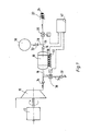
- a compressor 10 is driven by a motor 12.
- the compressor 10 supplies an output pressure which is effective in a compressed gas line 16 via a check valve 14.
- a molecular filter 18 is connected downstream of the compressor 10 in the compressed gas line 16.
- the molecular filter 18 can contain activated carbon, for example.
- One gram of activated carbon has a surface area of around 500 m2.
- the compressed gas line then leads via a controlled valve 20 to a cooling device 22 for a detector 24.
- the cooling device 22 uses the Joule-Thomson effect.
- the compressed gas is released through a nozzle and cools down.
- the relaxed and cooled gas flows over a heat exchanger located in the compressed gas line 16, so that the inflowing compressed gas is pre-cooled.
- the cooling device 22 is known per se and is therefore not shown and described in detail here. A very strong cooling of the detector 24 is thus achieved. At the low temperatures that occur, certain components of the sucked-in air can freeze out and thus render the cooling device 22 inoperable. To avoid
- a branch line 28 branches off from the compressed gas line 16 at a connection 26.
- the branch line 28 leads to a storage container 30.
- An adjustable throttle 32 is arranged in the branch line.
- a branch line 34 branches off from the compressed gas line 16.
- the branch line 34 contains a controlled valve 36 and is connected to an outlet via a check valve 37 opening in the outlet direction.
- the molecular filter 18 is via temperature control means in the form of Peltier elements 38 with a heat accumulator 40, i.e. a mass with a fairly large heat capacity.
- the housings of the compressor 10 and the motor 12 (or one of these) are preferably used as the heat accumulator 40.
- the controlled valves 20 and 36 and the Peltier elements 38 are controlled by a control device 42.
- the controlled valve 36 can be controlled in a first state, the controlled valve 20 can be controlled and the temperature-controlling means can be switched to the relatively low temperature, ie the Peltier elements 38 are flowed through in such a way that they extract heat from the molecular filter 18 and feed the heat accumulator 40.
- This is the normal operation of the device in which the cooling device 22 is in operation and the molecular filter 18 is kept at a low temperature in order to adsorb as much of the components of the compressed gas to be eliminated as possible.
- the controlled valve 36 can be opened, and the controlled valve 20 can be closed the temperature control means switchable to a relatively high temperature. Current then flows through the Peltier elements 38 such that the molecular filter 18 is heated.
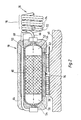
- the molecular filter 18 includes an elongated housing 50 having an inlet 52 at one end and an outlet 54 at the other end. At said one end an inlet chamber 56 is formed, into which the inlet 52 opens. At the other end, an outlet chamber 58 is formed from which the outlet extends. Between the inlet chamber 56 and outlet chamber 58, a filter insert 60 is arranged in the housing 50, which consists for example of activated carbon.
- the housing 50 is seated in a holding jacket 62, which ensures good heat conduction and distribution.
- the holding jacket 62 is seated via the Peltier elements 38 on the housing of the compressor 10 serving as a heat accumulator 40. Outside the area of the Peltier elements 32, the housing 50 and the holding jacket 62 are surrounded by a heat-insulating jacket 64.
- the pressure line 16 is connected to a section 66 on the compressor side with the inlet 52 and to a section 68 leading to the cooling device 22 with the outlet 54.
- the section 68 is guided through the insulating jacket 64 and the holding jacket 62 to the inlet side.
- the gas flowing in to the molecular filter 18 via section 66 is in heat exchange with the gas flowing out of the molecular filter 18 via section 68 through a countercurrent heat exchanger 70.
- the countercurrent heat exchanger 70 has tubes 72 for the inflowing gas, some of which of section 66 of pressure line 16, and pipes 74 for the outflowing gas, which form part of section 68 of pressure line 16.
- the tubes 72 and 74 are in close thermal contact with one another and are helically coiled together.
- the helically coiled tubes 72 and 74 act like a coil spring and are thus resilient in the axial direction.
- the molecular filter 18 is largely relieved of axial forces that could act via the compressed gas line 16.
- a temperature sensor 76 is attached to the molecular filter 18.
- the temperature sensor 76 applies a temperature signal to the control device 42.
- a temperature control can then be carried out in that the control device 42 contains a controller by means of which the temperature of the molecular filter 18 by means of the temperature-controlling means, i.e. of the Peltier elements 32, can be regulated to the relatively low temperature in the first state and to the relatively high temperature in the second state. Adsorption and desorption are then carried out at defined, regulated temperatures.
- Compressed gas 10 supplies compressed gas (compressed air) to the cooling device 22 via the compressed gas line 16 given and thus the detector 24 is strongly cooled. Unwanted components of this compressed gas are filtered out by adsorption through the molecular filter 18. As can be seen from FIG. 3, the higher the pressure and the lower the temperature, the more a certain amount of filter material such as activated carbon can absorb such components until saturation. Therefore, in normal operation, the molecular filter 18 is cooled by the Peltier elements 38. The pressure is the outlet pressure of the compressor 10 and is therefore relatively high. Both are favorable for adsorption. The effect is further improved and the transition to the low temperature is accelerated in that the compressed gas supplied to the molecular filter 18 is pre-cooled in the countercurrent heat exchanger 70 by the compressed gas flowing out of it.
- the storage container 30 is "charged", i.e. filled with compressed gas under the pressure supplied by the compressor 10 and prevailing in the compressed gas line.
- the regeneration of the molecular filter 18 is initiated by the control device. This can be done at fixed time intervals based on empirical values.
- the control device 42 then changes to the second state.
- the controlled valve 20 is closed, the controlled valve 36 is opened and the compressor 10 is switched off.
- the molecular filter 18 is heated by the Peltier elements 38.
- a flow of compressed gas flows from the storage container 30 via the throttle 32 in the opposite direction through the molecular filter 18 and via the branch line 34 to the outlet.
- the flow rate can be selected appropriately by the throttle 32.
- This flow causes the gas components adsorbed in the molecular filter 18 to be desorbed, which are then led to the outlet.
- the desorption rate i.e. the amount of gas desorbed from a given flow per unit of time, the higher the temperature and the lower the pressure.
- the desorption and thus the regeneration of the molecular filter 18 can thus take place in a time that is short compared to the time of normal operation.
- the effect is improved and the transition is accelerated by preheating the gas flowing to the molecular filter now via pipe 72 through the gas now flowing through pipe 74. It has been shown that the amount of gas stored in the storage container 30 is sufficient for the regeneration of the molecular filter 18.
Landscapes
- Physics & Mathematics (AREA)
- Engineering & Computer Science (AREA)
- General Physics & Mathematics (AREA)
- Spectroscopy & Molecular Physics (AREA)
- Mechanical Engineering (AREA)
- Thermal Sciences (AREA)
- General Engineering & Computer Science (AREA)
- Separation Of Gases By Adsorption (AREA)
- Radiation Pyrometers (AREA)
- Photometry And Measurement Of Optical Pulse Characteristics (AREA)
Abstract
Ein Detektor (24) bei einem optischen Sucher wird mittels des Joule-Thomson-Effekts durch Expansion von unter Druck stehendem Gas gekühlt. Das Druckgas wird von einem Kompressor (10) erzeugt und über ein Molekularfilter (18) auf eine Kühlvorrichtung (22) geleitet. Das Molekularfilter (18) adsorbiert störende Bestandteile des Druckgases. Zur Regeneration des Molekularfilters (18) wird in Abständen ein Gasstrom in umgekehrter Richtung von einem Speicherbehälter (30) durch das Molekularfilter (18) zu einem Auslaß geleitet. Im normalen Betrieb wird das Molekularfilter (18) durch Peltier-Elemente (38) gekühlt. Bei der Regeneration wird es beheizt. 
Description
Die Erfindung betrifft eine Vorrichtung zum Kühlen eines Detektors, insbesondere bei einem optischen Sucher, mittels des Joule-Thomson-Effektes durch Expansion von unter Druck stehendem Gas, enthaltend
- (a) einen Kompressor zum Ansaugen und Komprimieren des Gases in einer zu dem Detektor führenden Druckgasleitung und
- (b) ein Molekularfilter, welches dem Kompressor nachgeschaltet ist, zum Adsorbieren von störenden Bestandteilen des Gases.
- (a) a compressor for sucking and compressing the gas in a compressed gas line leading to the detector and
- (b) a molecular filter, which is connected downstream of the compressor, for adsorbing interfering components of the gas.
Es ist bekannt, Detektoren für optische Sucher bei zielsuchenden Flugkörpern unter Ausnutzung des Joule-Thomson-Effektes zu kühlen. Dadurch wird das Signal-zu-Rausch Verhältnis des Detektors insbesondere im infraroten Bereich entscheidend verbessert. Das zu entspannende, unter Druck stehende Gas wird dabei einer Gasflasche entnommen. Da es nicht nur erforderlich ist, den Detektor im Zeitpunkt des Abschlusses und während der Zielverfolgung so zu kühlen sondern der Detektor während der gesammten Mission des Flugkörperträgers gekühlt gehalten werden muß, ist der Gasverbrauch recht hoch. Die Gasflaschen müssen daher regelmäßig ersetzt werden. Wird dies vergessen, dann kann der Sucher zu einem kritischen Zeitpunkt dadurch funktionsunfähig werden, daß der Gasvorrat zu Ende geht und die Kühlung des Detektors wegfällt.It is known to cool detectors for optical viewfinders in target-seeking missiles using the Joule-Thomson effect. This significantly improves the signal-to-noise ratio of the detector, particularly in the infrared range. The pressurized gas to be released is removed from a gas bottle. Since it is not only necessary to cool the detector at the time of completion and during target tracking, but the detector must be kept cool throughout the missile carrier's mission, the gas consumption is quite high. The gas cylinders must therefore be replaced regularly. If this is forgotten, the viewfinder can become inoperable at a critical time by the gas supply running out and the cooling of the detector being eliminated.
Es ist daher schon vorgeschlagen worden, als für den Joule-Thomson-Effekt zu entspannendes Druckgas Druckluft zu verwenden, die mittels eines Kompressors an gesaugt und komprimiert wird. Diese Druckluft wird über eine Druckgasleitung zum Detektor geleitet und dort unter Abkühlung entspannt. Durch Wärmeaustausch in einem Gegenstromverfahren erfolgt dabei eine Vorkühlung der zu entspannenden Druckluft, so daß dabei außerordentlich tiefe Temperaturen erreicht werden.It has therefore already been proposed to use compressed air as the compressed gas to be relaxed for the Joule-Thomson effect, which is sucked in and compressed by means of a compressor. This compressed air is conducted to the detector via a compressed gas line and is expanded there with cooling. By heat exchange in a countercurrent process, the compressed air to be expanded is precooled so that extremely low temperatures are reached.
Ein Austausch von Gasflaschen kann dann entfallen. Es ergibt sich jedoch ein anderes Problem: Das Gas in den Gasflaschen ist rein. Die angesaugte Luft enthält jedoch gasförmige Bestandteile die bei vergleichsweise hohen Temperaturen kondensieren oder gefrieren, beispielsweise Wasserdampf oder Kohlendioxid. Solche Bestandteile der Luft würden im Bereich des gekühlten Detektors kondensieren oder gefrieren und dadurch das Kühlsystem in kurzer Zeit funktionsunfähig machen, beispielsweise durch Verstopfen der Druckgasleitung oder der Austrittdüse, über welche die Entspannung der Druckluft stattfindet.An exchange of gas bottles can then be omitted. However, there is another problem: the gas in the gas bottles is pure. However, the sucked-in air contains gaseous components that condense or freeze at comparatively high temperatures, for example water vapor or carbon dioxide. Such components of the air would condense or freeze in the area of the cooled detector and thereby the Make the cooling system inoperable in a short time, for example by clogging the compressed gas line or the outlet nozzle, via which the expansion of the compressed air takes place.
Es ist daher erforderlich, die störenden Bestandteile vorher aus der Druckluft zu entfernen. Zu diesem Zweck ist vorgeschlagen worden, dem Kompressor ein Molekularfilter nachzuschalten, welches die störenden Bestandteile des Gases adsorbiert. Ein solches Filter wird jedoch nach einer bestimmten Zeit, die von seiner Oberfläche und damit von seiner Größe abhängt, gesättigt. Um ein solches Molekularfilter über einen längeren Zeitraum betriebsbereit zu halten, muß das Molekularfilter daher ziemlich groß sein. Das ist nachteilig. Bei kleinen Molekularfiltern ist ein häufiger Wechsel erforderlich.It is therefore necessary to remove the disruptive components from the compressed air beforehand. For this purpose, it has been proposed to connect a molecular filter to the compressor, which adsorbs the interfering constituents of the gas. However, such a filter becomes saturated after a certain time, which depends on its surface and thus on its size. In order to keep such a molecular filter operational for a longer period of time, the molecular filter must therefore be quite large. That is disadvantageous. A frequent change is required for small molecular filters.
Damit ist im Grunde das Problem nur verschoben worden: Statt eines Wechsels der Gasflasche ist nun ein Wechsel des Molekularfilters erforderlich. Ein Versäumnis in dieser Hinsicht kann ebenfalls zur Funktionsunfähigkeit des Suchers zur Unzeit führen. Wenn das Molekularfilter gesättigt ist, adsorbiert es die störenden Bestandteile nicht mehr. Diese können sich dann wie beschrieben im Bereich des gekühlten Detektors niederschlagen und gefrieren.Basically, the problem has only been postponed: Instead of changing the gas bottle, it is now necessary to change the molecular filter. Failure to do so may also cause the viewfinder to malfunction at the wrong time. When the molecular filter is saturated, it no longer adsorbs the interfering components. As described, these can then precipitate and freeze in the area of the cooled detector.
Der Erfindung liegt die Aufgabe zugrunde, eine Vorrichtung der eingangs genannten Art so auszubilden, daß die Notwendigkeit des Austauschs von Teilen entfällt.The invention has for its object to design a device of the type mentioned so that the need to replace parts is eliminated.
Eine weitere, speziellere Aufgabe der Erfindung besteht darin, die Verwendung eines möglichst kleinen Molekularfilters zu ermöglichen.Another, more specific object of the invention is to enable the use of the smallest possible molecular filter.
Erfindungsgemäß wird diese Aufgabe dadurch gelöst, daß
- (c) mit der Druckgasleitung stromab von dem Molekularfilter ein Speicherbehälter verbunden ist,
- (d) die Druckgasleitung zwischen Kompressor und Molekularfilter über ein gesteuertes Ventil mit einem Auslaß verbindbar ist,
- (e) temperatursteuernde Mittel zur Veränderung der Temperatur des Molekularfilters zwischen einem relativ niedrigen und einem relativ hohen Wert vorgesehen sind,
- (f) eine Steuervorrichtung vorgesehen ist, durch welche
-in einem ersten Zustand das gesteuerte Ventil zusteuerbar ist und die temperatursteuernden Mittel auf die relativ niedrige Temperatur umschaltbar sind und
-in einem zweiten Zustand das gesteuerte Ventil aufsteuerbar ist und die temperatursteuernden Mittel auf die relativ hohe Temperatur umschaltbar sind, und - (g) die Steuervorrichtung normalerweise in dem ersten Zustand ist und in Zeitabständen in den zweiten Zustand schaltet.
- (c) a storage container is connected to the compressed gas line downstream of the molecular filter,
- (d) the compressed gas line between the compressor and the molecular filter can be connected to an outlet via a controlled valve,
- (e) temperature-controlling means are provided for changing the temperature of the molecular filter between a relatively low and a relatively high value,
- (f) a control device is provided by which
in a first state the controlled valve can be activated and the temperature-controlling means can be switched to the relatively low temperature and
in a second state the controlled valve can be opened and the temperature-controlling means can be switched to the relatively high temperature, and - (g) the control device is normally in the first state and switches to the second state at intervals.
Während des normalen Betriebs wird der Speicherbehälter "aufgeladen", d.h. mit Druckgas unter dem stromab von dem Molekularfilter herrschenden Druck gefüllt. In bestimmten zeitlichen Abständen, welche durch die Steuervorrichtung bestimmt sind,wird dann die Druckgasleitung stromab vom Anschluß des Speicherbehälters abgesperrt und gleichzeitig ein Auslaß stromauf von dem Molekularfilter geöffnet. Es strömt jetzt Gas aus dem Speicherbehälter rückwärts durch das Molekularfilter zum Auslaß. Während die Adsorption am Molekularfilter bei einer relativ zu der Rückspültemperatur niedrigen Temperatur und hohem Druck, nämlich dem Ausgangsdruck des Kompressors, erfolgt, wird beim Rückspülen mit einer relativ zu der normalen Arbeitstemperatur hohen Temperatur des Molekularfilters und einem niedrigen Druck, nämlich dem Auslaßdruck gearbeitet. Die niedrige Temperatur und der hohe Druck begünstigen die Adsorption. Die hohe Temperatur und der niedrige Druck begünstigen das Austreiben der adsorbierten Bestandteile während des Rückspülens. Infolgedessen reicht die in dem Speicherbehälter gespeicherte Gasmenge aus, um das Molekularfilter von den adsorbierten Bestandteilen wieder zu befreien und für den normalen Kühlbetrieb funktionsfähig zu machen. Diese Anordnung ist für den Dauerbetrieb geeignet. Es ist kein regelmäßiger Austausch von Gasflaschen oder Molekularfiltern erforderlich wie bei den früheren Vorschlägen. Das Molekularfilter kann raumsparend ausgebildet werden, da es regeneriert wird, bevor eine Sättigung eintritt.During normal operation, the storage container is "charged", ie filled with compressed gas under the pressure prevailing downstream of the molecular filter. In Certain time intervals, which are determined by the control device, the compressed gas line downstream of the connection of the storage container is then shut off and at the same time an outlet upstream of the molecular filter is opened. Gas now flows backwards from the storage container through the molecular filter to the outlet. While adsorption on the molecular filter takes place at a temperature and pressure, namely the outlet pressure of the compressor, which is low relative to the backwash temperature, backwashing is carried out with a temperature of the molecular filter which is high relative to the normal working temperature and a low pressure, namely the outlet pressure. The low temperature and the high pressure favor the adsorption. The high temperature and the low pressure promote the expulsion of the adsorbed components during backwashing. As a result, the amount of gas stored in the storage container is sufficient to remove the adsorbed constituents from the molecular filter again and to make it functional for normal cooling operation. This arrangement is suitable for continuous operation. There is no need to replace gas cylinders or molecular filters on a regular basis as in the previous proposals. The molecular filter can be designed to save space because it is regenerated before saturation occurs.
Ausgestaltungen der Erfindung sind Gegenstand der Unteransprüche.Embodiments of the invention are the subject of the dependent claims.
Ein Ausführungsbeispiel der Erfindung ist nachstehend unter Bezugnahme auf die zugehörigen Zeichnungen näher erläutert:
- Fig. 1 ist ein schematisches Schaltbild einer Vorrichtung zum Kühlen eines Detektors.
- Fig. 2 zeigt einen Längsschnitt des Molekularfilters mit den temperatursteuernden Mitteln in Form von Peltier-Elementen und der Druckgasleitung.
- Fig. 3 zeigt im Prinzip die Abhängigkeit der Adsortion vom Druck für verschiedene Temperaturen.
- Fig. 4 zeigt im Prinzip die Abhängigkeit der Desorptionsrate vom Druck für verschiedene Temperaturen.
- 1 is a schematic circuit diagram of an apparatus for cooling a detector.
- Fig. 2 shows a longitudinal section of the molecular filter with the temperature-controlling means in the form of Peltier elements and the compressed gas line.
- Fig. 3 shows in principle the dependence of the adsorption on the pressure for different temperatures.
- Fig. 4 shows in principle the dependence of the desorption rate on the pressure for different temperatures.
Ein Kompressor 10 wird von einem Motor 12 angetrieben. Der Kompressor 10 liefert einen Ausgangsdruck, der über ein Rückschlagventil 14 in einer Druckgasleitung 16 wirksam wird. Dem Kompressor 10 ist in der Druckgasleitung 16 ein Molekularfilter 18 nachgeschaltet. Das Molekularfilter 18 kann beispielsweise Aktivkohle enthalten. Ein Gramm Aktivkohle hat eine Oberfläche von etwa 500 m². Die Druckgasleitung führt dann über ein gesteuertes Ventil 20 zu einer Kühlvorrichtung 22 für einen Detektor 24. Die Kühlvorrichtung 22 nutzt den Joule-Thomson-Effekt aus. Das Druckgas wird über eine Düse entspannt und kühlt sich dabei ab. Das entspannte und abgekühlte Gas strömt über einen in der Druckgasleitung 16 sitzenden Wärmetauscher, so daß das zuströmende Druckgas vorgekühlt wird. Die Kühlvorrichtung 22 ist an sich bekannt und daher hier nicht im einzelnen dargestellt und beschrieben. Es wird damit eine sehr starke Abkühlung des Detektors 24 erreicht. Bei den dabei auftretenden niedrigen Temperaturen können bestimmte Bestandteile der angesaugten Luft ausfrieren und damit die Kühlvorrichtung 22 funktionsunfähig machen. Um das zu vermeiden, werden solche Bestandteile durch das Molekularfilter 18 entfernt.A
Stromab von dem Molekularfilter 18 zweigt an einem Anschluß 26 von der Druckgasleitung 16 eine Zweigleitung 28 ab. Die Zweigleitung 28 führt zu einem Speicherbehälter 30. In der Zweigleitung ist eine einstellbare Drossel 32 angeordnet. Stromauf von dem Molekularfilter 18 zwischen dem Molekularfilter 18 und dem Rückschlagventil 14 zweigt von der Druckgasleitung 16 eine Zweigleitung 34 ab. Die Zweigleitung 34 enthält ein gesteuertes Ventil 36 und ist über ein in Auslaßrichtung öffnendes Rückschlagventil 37 mit einem Auslaß verbunden.Downstream of the
Das Molekularfilter 18 ist über temperatursteuernde Mittel in Form von Peltier-Elementen 38 mit einem Wärmespeicher 40, d.h. einer Masse mit ziemlich großer Wärmekapazität, verbunden. Als Wärmespeicher 40 dienen vorzugsweise die Gehäuse des Kompressors 10 und des Motors 12 (oder eines von diesen).The
Die gesteuerten Ventile 20 und 36 sowie die Peltier-Elemente 38 werden von einer Steuervorrichtung 42 gesteuert. Durch die Steuervorrichtung 42 ist in einem ersten Zustand das gesteuerte Ventil 36 zusteuerbar, das gesteuerte Ventil 20 aufsteuerbar und sind die temperatursteuernden Mittel auf die relativ niedrige Temperatur umschaltbar, d.h. sind die Peltier-Elemente 38 so stromdurchflossen, daß sie dem Molekularfilter 18 Wärme entziehen und dem Wärmespeicher 40 zuführen. Das ist der normale Betrieb der Vorrichtung, bei welchem die Kühlvorrichtung 22 in Betrieb ist und das Molekularfilter 18 auf niedriger Temperatur gehalten wird, um möglichst viel von den zu eliminierenden Bestandteilen des Druckgases zu adsorbieren. In einem zweiten Zustand ist das gesteuerte Ventil 36 aufsteuerbar das gesteuerte Ventil 20 zusteuerbar und die sind die temperatursteuernden Mittel auf eine relativ hohe Temperatur umschaltbar. Die Peltier-Elemente 38 werden dann so von Strom durchflossen, daß das Molekularfilter 18 aufgeheizt wird.The controlled
In Fig. 2 ist der konstruktive Aufbau des Molekularfilters 18 dargestellt. Das Molekularfilter 18 enthält ein langgestrecktes Gehäuse 50 mit einem Einlaß 52 an einem Ende und einem Auslaß 54 am anderen Ende. An dem besagten einen Ende ist eine Einlaßkammer 56 gebildet, in welche der Einlaß 52 mündet. An dem besagten anderen Ende ist eine Auslaßkammer 58 gebildet, von welcher der Auslaß abgeht. Zwischen Einlaßkammer 56 und Auslaßkammer 58 ist in dem Gehäuse 50 ein Filtereinsatz 60 angeordnet, der beispielsweise aus Aktivkohle besteht. Das Gehäuse 50 sitzt in einem Haltemantel 62, der eine gute Wärmeleitung und -verteilung gewährleistet. Der Haltemantel 62sitzt über die Peltier-Elemente 38 auf dem als Wärmespeicher 40 dienenden Gehäuse des Kompressors 10. Außerhalb des Bereiches der Peltier-Elemente 32 sind das Gehäuse 50 und der Haltemantel 62 von einem wärmeisolierenden Mantel 64 umgeben.2 shows the structural design of the
Die Druckleitung 16 ist mit einem kompressorseitigen Abschnitt 66 mit dem Einlaß 52 und mit einem zu der Kühlvorrichtung 22 führenden Abschnitt 68 mit dem Auslaß 54 verbunden. Der Abschnitt 68 ist durch den isolierenden Mantel 64 und den Haltemantel 62 hindurch zur Einlaßseite geführt. Durch einen Gegenstrom-Wärmetauscher 70 steht das dem Molekularfilter 18 über Abschnitt 66 zuströmende Gas mit dem aus dem Molekularfilter 18 über Abschnitt 68 abströmenden Gas in Wärmeaustausch. Der Gegenstrom-Wärmetauscher 70 weist Rohre 72 für das zuströmende Gas auf, die einen Teil des Abschnitts 66 der Druckleitung 16 bilden, und Rohre 74 für das abströmende Gas, die einen Teil des Abschnitts 68 der Druckleitung 16 bilden. Die Rohre 72 und 74 stehen in engem wärmeleitenden Kontakt miteinander und sind zusammen schraubenförmig gewendelt. Die schraubenförmig gewendelten Rohre 72 und 74 wirken wie eine Wendelfeder und sind somit in axialer Richtung federnd. Dadurch wird das Molekularfilter 18 von axialen Kräften, die über die Druckgasleitung 16 wirksam werden könnten, weitgehend entlastet. Es wird auf diese Weise möglich, daß das Molekularfilter 18, wie dargestellt, nur über die Petier-Elemente 32 auf dem Wärmespeicher 40 abgestützt ist. Auf diese Weise wird die Isollation des Molekularfilters 18 verbessert und es wird ein unkontrollierter Wärmeabfluß oder - zufluß über zusätzliche Halterungselemente vermieden.The
An dem Molekularfilter 18 ist ein Temperaturfühler 76 angebracht. Der Temperaturfühler 76 schaltet ein Temperatursignal auf die Steuervorrichtung 42 auf. Es kann dann eine Temperaturregelung erfolgen, indem die Steuervorrichtung 42 einen Regler enthält, durch welchen die Temperatur des Molekularfilters 18 mittels der temperatursteuernden Mittel, d.h. der Peltier-Elemente 32, in dem ersten Zustand auf die relativ niedrige Tempertur und in dem zweiten Zustand auf die relativ hohe Temperatur regelbar ist. Es wird dann bei Adsorption und Desorption bei definierten, geregelten Temperaturen gearbeitet.A
Die beschriebene Vorrichtung arbeitet wie folgt:The described device works as follows:
Durch den Kompressor 10 wird Druckgas (Druckluft) über die Druckgasleitung 16 auf die Kühlvorrichtung 22 gegeben und damit der Detektor 24 stark gekühlt. Durch das Molekularfilter 18 werden unerwünschte Bestandteile dieses Druckgases durch Adsorption herausgefiltert. Wie aus Fig. 3 ersichtlich ist, kann eine bestimmte Menge von Filtermaterial wie Aktivkohle bis zur Sättigung umso mehr an solchen Bestandteilen aufnehmen, je höher der Druck und je niedriger die Temperatur ist. Deshalb wird bei der normalen Betriebsweise das Molekularfilter 18 durch die Peltier-Elemente 38 gekühlt. Der Druck ist der Ausgangsdruck des Kompressors 10 und daher relativ hoch. Beides ist günstig für die Adsorption. Der Effekt wird noch dadurch verbessert und der Übergang zu der niedrigen Temperatur wird dadurch beschleunigt, daß das dem Molekularfilter 18 zugeführte Druckgas in dem Gegenstrom- Wärmetauscher 70 durch das aus diesem abströmende Druckgas vorgekühlt wird.
Gleichzeitig wird über die Zweigleitung 28 und die Drossel 32 der Speicherbehälter 30, "aufgeladen", d.h. mit Druckgas unter dem vom Kompressor 10 gelieferten, in der Druckgasleitung herrschenden Druck gefüllt.Simultaneously, via the
Wenn schließlich sich das Molekularfilter 18 trotzdem dem Zustand der Sättigung nähert, wird von der Steuervorrichtung die Regeneration des Molekularfilters 18 eingeleitet. Das kann in fest vorgegebenen, aus Erfahrungswerten resultierenden Zeitabständen geschehen. Die Steuervorrichtung 42 geht dann in den zweiten Zustand über. Das gesteuerte Ventil 20 wird geschlossen, das gesteuerte Ventil 36 wird geöffnet und der Kompressor 10 wird abgeschaltet. Gleichzeitig wird das Molekularfilter 18 durch die Peltier-Elemente 38 beheizt.Finally, if the
Dadurch fließt eine Strömung von Druckgas aus dem Speicherbehälter 30 über die Drossel 32 in umgekehrter Richtung durch das Molekularfilter 18 und über die Zweigleitung 34 zum Auslaß. Die Strömungsrate kann durch die Drossel 32 geeignet gewählt werden. Durch diese Strömung erfolgt eine Desorption der in dem Molekularfilter 18 adsorbierten Gasbestandteile, die dann zum Auslaß geführt werden. Wie aus Fig. 4 ersichtlich ist, ist die Desorptionsrate, d.h. die Menge des von einer bestimmten Strömung pro Zeiteinheit desorbierten Gases, umso höher, je höher die Temperatur und je niedriger der Druck ist. Gerade diese Bedingungen werden in dem zweiten Zustand der Steuervorrichtung erfüllt: Die Temperatur des Molekularfilters 18 wird erhöht. Der Druck wird durch die Verbindung mit dem Auslaß über das geöffnete Ventil 36 und den Druckabfall an der Drossel 32 verringert. Die Desorption und damit die Regeneration des Molekularfilters 18 kann dadurch in einer im ergleich zu der Zeit des normalen Betriebs kurzen Zeit erfolgen. Auch hier wird der Effekt verbessert und der Übergang beschleunigt, indem das dem Molekularfilter -jetzt über Rohr 72- zuströmende Gas durch das -jetzt uber Rohr 74-abströmende Gas vorgewärmt wird. Es hat sich gezeigt, daß die in dem Speicherbehälter 30 gespeicherte Gasmenge für die Regeneration des Molekularfilters 18 ausreicht.As a result, a flow of compressed gas flows from the
Claims (12)
(a) einen Kompressor (10) zum Ansaugen und Komprimieren des Gases in einer zu dem Detektor (24) führenden Druckgasleitung (16) und
(b) ein Molekularfilter (18), welches dem Kompressor (10) nachgeschaltet ist, zum Adsorbieren von störenden Bestandteilen des Gases,
dadurch gekennzeichnet, daß
(c) mit der Druckgasleitung (16) stromab von dem Molekularfilter (18) ein Speicherbehälter (30) verbunden ist,
(d) die Druckgasleitung (16) zwischen Kompressor (10) und Molekularfiler (18) über ein gesteuertes Ventil (36) mit einem Auslaß verbindbar ist,
(e) temperatursteuernde Mittel (38) zur Veränderung der Temperatur des Molekularfilters (18) zwischen einem relativ niedrigen und einem relativ hohen Wert vorgesehen sind,
(f) eine Steuervorrichtung (42) vorgesehen ist,
durch welche
-in einem ersten Zustand das gesteuerte Ventil (36) zusteuerbar ist und die temperatursteuernden Mittel (38) auf die relativ niedrige Temperatur umschaltbar sind und
-in einem zweiten Zustand das gesteuerte Ventil (36) aufsteuerbar ist und die temperatursteuernden Mittel (38) auf die relativ hohe Temperatur umschaltbar sind, und
(g) die Steuervorrichtung (42) normalerweise in dem ersten Zustand ist und in Zeitabständen in den zweiten Zustand schaltet.1. Device for cooling a detector (24), in particular in an optical viewfinder, by means of the Joule-Thomson effect by expanding gas under pressure
(a) a compressor (10) for sucking and compressing the gas in a compressed gas line (16) leading to the detector (24) and
(b) a molecular filter (18), which is connected downstream of the compressor (10), for adsorbing interfering constituents of the gas,
characterized in that
(c) a storage container (30) is connected to the compressed gas line (16) downstream of the molecular filter (18),
(d) the compressed gas line (16) between the compressor (10) and the molecular filter (18) can be connected to an outlet via a controlled valve (36),
(e) temperature-controlling means (38) are provided for changing the temperature of the molecular filter (18) between a relatively low and a relatively high value,
(f) a control device (42) is provided,
by which
in a first state the controlled valve (36) can be activated and the temperature-controlling means (38) can be switched to the relatively low temperature and
in a second state the controlled valve (36) can be opened and the temperature-controlling means (38) can be switched to the relatively high temperature, and
(g) the control device (42) is normally in the first state and switches to the second state at intervals.
-in dem ersten Zustand das zweite gesteuerte Ventil (20) aufsteuerbar und
-in dem zweiten Zustand das zweite gesteuerte Ventil (20) zusteuerbar ist.
in the first state, the second controlled valve (20) can be opened and
- In the second state, the second controlled valve (20) can be activated.
Applications Claiming Priority (2)
| Application Number | Priority Date | Filing Date | Title |
|---|---|---|---|
| DE19863611206 DE3611206A1 (en) | 1986-04-04 | 1986-04-04 | DEVICE FOR COOLING A DETECTOR, IN PARTICULAR WITH AN OPTICAL VIEWFINDER |
| DE3611206 | 1986-04-04 |
Publications (3)
| Publication Number | Publication Date |
|---|---|
| EP0240774A2 true EP0240774A2 (en) | 1987-10-14 |
| EP0240774A3 EP0240774A3 (en) | 1990-03-07 |
| EP0240774B1 EP0240774B1 (en) | 1991-09-11 |
Family
ID=6297855
Family Applications (1)
| Application Number | Title | Priority Date | Filing Date |
|---|---|---|---|
| EP87103743A Expired - Lifetime EP0240774B1 (en) | 1986-04-04 | 1987-03-14 | Detector-cooling device, particularly for an optical tracer |
Country Status (3)
| Country | Link |
|---|---|
| US (1) | US4750338A (en) |
| EP (1) | EP0240774B1 (en) |
| DE (2) | DE3611206A1 (en) |
Cited By (1)
| Publication number | Priority date | Publication date | Assignee | Title |
|---|---|---|---|---|
| EP1920983A3 (en) * | 2006-11-09 | 2009-04-22 | Bendix Commercial Vehicle Systems LLC | Cartridge life tester |
Families Citing this family (18)
| Publication number | Priority date | Publication date | Assignee | Title |
|---|---|---|---|---|
| DE4131529C2 (en) * | 1991-09-21 | 1994-03-31 | Bodenseewerk Geraetetech | Device for releasing the coolant supply in a missile |
| DE4226024C1 (en) * | 1992-08-06 | 1993-07-15 | Bodenseewerk Geraetetechnik Gmbh, 7770 Ueberlingen, De | |
| US5551244A (en) * | 1994-11-18 | 1996-09-03 | Martin Marietta Corporation | Hybrid thermoelectric/Joule-Thomson cryostat for cooling detectors |
| US5606870A (en) * | 1995-02-10 | 1997-03-04 | Redstone Engineering | Low-temperature refrigeration system with precise temperature control |
| GB9505915D0 (en) * | 1995-03-23 | 1995-05-10 | Ultra Electronics Ltd | Cooler |
| GB9506652D0 (en) * | 1995-03-31 | 1995-05-24 | Cryogenic Technology Ltd | Supplying liquid cryogen to cryosurgical apparatus |
| DE19733455B4 (en) * | 1997-08-02 | 2012-03-29 | Curamik Electronics Gmbh | Heat exchanger assembly and cooling system with at least one such heat exchanger assembly |
| DE19823996A1 (en) * | 1998-05-28 | 1999-12-02 | Siemens Ag | Compressor arrangement with cooling device |
| US20070101737A1 (en) * | 2005-11-09 | 2007-05-10 | Masao Akei | Refrigeration system including thermoelectric heat recovery and actuation |
| US8950206B2 (en) * | 2007-10-05 | 2015-02-10 | Emerson Climate Technologies, Inc. | Compressor assembly having electronics cooling system and method |
| US20090241592A1 (en) * | 2007-10-05 | 2009-10-01 | Emerson Climate Technologies, Inc. | Compressor assembly having electronics cooling system and method |
| US7895003B2 (en) * | 2007-10-05 | 2011-02-22 | Emerson Climate Technologies, Inc. | Vibration protection in a variable speed compressor |
| US8459053B2 (en) * | 2007-10-08 | 2013-06-11 | Emerson Climate Technologies, Inc. | Variable speed compressor protection system and method |
| US9541907B2 (en) | 2007-10-08 | 2017-01-10 | Emerson Climate Technologies, Inc. | System and method for calibrating parameters for a refrigeration system with a variable speed compressor |
| US8418483B2 (en) * | 2007-10-08 | 2013-04-16 | Emerson Climate Technologies, Inc. | System and method for calculating parameters for a refrigeration system with a variable speed compressor |
| US8539786B2 (en) | 2007-10-08 | 2013-09-24 | Emerson Climate Technologies, Inc. | System and method for monitoring overheat of a compressor |
| US8448459B2 (en) * | 2007-10-08 | 2013-05-28 | Emerson Climate Technologies, Inc. | System and method for evaluating parameters for a refrigeration system with a variable speed compressor |
| US11206743B2 (en) | 2019-07-25 | 2021-12-21 | Emerson Climate Technolgies, Inc. | Electronics enclosure with heat-transfer element |
Family Cites Families (9)
| Publication number | Priority date | Publication date | Assignee | Title |
|---|---|---|---|---|
| US3225517A (en) * | 1963-01-22 | 1965-12-28 | Joy Mfg Co | Gas drying method |
| GB1125437A (en) * | 1964-12-11 | 1968-08-28 | English Electric Co Ltd | Improvements in electrical transformers and reactors |
| US3413819A (en) * | 1966-05-09 | 1968-12-03 | Hughes Aircraft Co | Flow rate control for a joule-thomson refrigerator |
| US3488971A (en) * | 1968-04-29 | 1970-01-13 | Gershon Meckler | Comfort conditioning system |
| US4080802A (en) * | 1976-07-14 | 1978-03-28 | International Telephone And Telegraph Corporation | Hybrid gas cryogenic cooler |
| DE3106469A1 (en) * | 1981-02-21 | 1982-09-09 | Herbert Dr.-Ing. 5963 Wenden Brandt | Control device for purging-air consumption in the regeneration of the adsorbent in an appliance for generating dry compressed air |
| DE3216815A1 (en) * | 1982-05-05 | 1983-11-10 | Knorr-Bremse GmbH, 8000 München | CONTROL DEVICE FOR REGENERATING AN AIR DRYER FOR A PNEUMATIC SYSTEM, ESPECIALLY A VEHICLE BRAKE SYSTEM |
| DE8405789U1 (en) * | 1984-02-25 | 1985-06-20 | Robert Bosch Gmbh, 7000 Stuttgart | Air dryer |
| EP0239375A3 (en) * | 1986-03-24 | 1988-11-17 | British Aerospace Public Limited Company | De-contaminated fluid supply apparatus and cryogenic cooling systems using such apparatus |
-
1986
- 1986-04-04 DE DE19863611206 patent/DE3611206A1/en not_active Ceased
-
1987
- 1987-03-14 DE DE8787103743T patent/DE3772806D1/en not_active Expired - Fee Related
- 1987-03-14 EP EP87103743A patent/EP0240774B1/en not_active Expired - Lifetime
- 1987-04-02 US US07/034,104 patent/US4750338A/en not_active Expired - Fee Related
Cited By (1)
| Publication number | Priority date | Publication date | Assignee | Title |
|---|---|---|---|---|
| EP1920983A3 (en) * | 2006-11-09 | 2009-04-22 | Bendix Commercial Vehicle Systems LLC | Cartridge life tester |
Also Published As
| Publication number | Publication date |
|---|---|
| EP0240774B1 (en) | 1991-09-11 |
| DE3772806D1 (en) | 1991-10-17 |
| DE3611206A1 (en) | 1987-10-08 |
| EP0240774A3 (en) | 1990-03-07 |
| US4750338A (en) | 1988-06-14 |
Similar Documents
| Publication | Publication Date | Title |
|---|---|---|
| EP0240774B1 (en) | Detector-cooling device, particularly for an optical tracer | |
| DE3808653C2 (en) | Process for operating an adsorption refrigeration system | |
| DE2500303C3 (en) | Cooling system | |
| DE4030145C1 (en) | ||
| DE69615071T2 (en) | Process and system for cryogenic vapor recovery | |
| DE69525034T2 (en) | Heat recovery in a pressure swing adsorption process | |
| DE1619851B2 (en) | DEVICE FOR DRYING COMPRESSED GAS | |
| DE102011102036B4 (en) | Method for operating a cyclically operating thermal adsorption heat plant and apparatus | |
| EP0520335A1 (en) | Sorption system with regenerative heat exchange | |
| DE3150624A1 (en) | Process and equipment for separating a crude gas mixture | |
| DE1929042U (en) | DEVICE FOR SEPARATING HYDROGEN OF HIGH PURITY FROM A HYDROGEN-NITROGEN MIXTURE. | |
| DE102013012656A1 (en) | A method of separating unwanted components from a helium stream | |
| DE69100730T2 (en) | Heat pump. | |
| DE2901894A1 (en) | PROCEDURE FOR OPERATING AN ADSORBER SYSTEM AND ADSORBER SYSTEM FOR CARRYING OUT THIS PROCEDURE | |
| DE102018205890A1 (en) | Continuous water extraction device for a motor vehicle | |
| DE19527960C2 (en) | Method and device for desorbing adsorbers | |
| DE2828914A1 (en) | Drying and cooling plant - uses circulating gas which is cooled and expanded with part of compressed stream tapped for regeneration | |
| DE3743681C1 (en) | Process for regenerating an adsorber laden with a solvent | |
| DE1955617A1 (en) | Method and device for drying compressed gases with adsorbable components | |
| DE10100114A1 (en) | Regenerating loaded adsorber comprises using regenerating gas heated using hot thermal oil stream | |
| DE102018002120A1 (en) | Device for tempering filter-cleaned liquid medium | |
| DE202018001404U1 (en) | Device for tempering filter-cleaned liquid medium | |
| DE2734934A1 (en) | Heat recovery system for air separation - having regenerators with side stream to heat exchanger to ensure full heat recovery | |
| DE29909574U1 (en) | Device for drying and heating air for drying solids | |
| DE4311954A1 (en) | Rotor adsorber for separation and recovery of minor components from gas streams |
Legal Events
| Date | Code | Title | Description |
|---|---|---|---|
| PUAI | Public reference made under article 153(3) epc to a published international application that has entered the european phase |
Free format text: ORIGINAL CODE: 0009012 |
|
| AK | Designated contracting states |
Kind code of ref document: A2 Designated state(s): DE FR GB IT SE |
|
| PUAL | Search report despatched |
Free format text: ORIGINAL CODE: 0009013 |
|
| AK | Designated contracting states |
Kind code of ref document: A3 Designated state(s): DE FR GB IT SE |
|
| 17P | Request for examination filed |
Effective date: 19900613 |
|
| 17Q | First examination report despatched |
Effective date: 19900919 |
|
| GRAA | (expected) grant |
Free format text: ORIGINAL CODE: 0009210 |
|
| AK | Designated contracting states |
Kind code of ref document: B1 Designated state(s): DE FR GB IT SE |
|
| REF | Corresponds to: |
Ref document number: 3772806 Country of ref document: DE Date of ref document: 19911017 |
|
| GBT | Gb: translation of ep patent filed (gb section 77(6)(a)/1977) | ||
| ITF | It: translation for a ep patent filed | ||
| ET | Fr: translation filed | ||
| PLBE | No opposition filed within time limit |
Free format text: ORIGINAL CODE: 0009261 |
|
| STAA | Information on the status of an ep patent application or granted ep patent |
Free format text: STATUS: NO OPPOSITION FILED WITHIN TIME LIMIT |
|
| 26N | No opposition filed | ||
| PGFP | Annual fee paid to national office [announced via postgrant information from national office to epo] |
Ref country code: SE Payment date: 19940222 Year of fee payment: 8 |
|
| EAL | Se: european patent in force in sweden |
Ref document number: 87103743.8 |
|
| PG25 | Lapsed in a contracting state [announced via postgrant information from national office to epo] |
Ref country code: SE Effective date: 19950315 |
|
| EUG | Se: european patent has lapsed |
Ref document number: 87103743.8 |
|
| PGFP | Annual fee paid to national office [announced via postgrant information from national office to epo] |
Ref country code: FR Payment date: 19970227 Year of fee payment: 11 |
|
| PGFP | Annual fee paid to national office [announced via postgrant information from national office to epo] |
Ref country code: DE Payment date: 19970521 Year of fee payment: 11 |
|
| PGFP | Annual fee paid to national office [announced via postgrant information from national office to epo] |
Ref country code: GB Payment date: 19980312 Year of fee payment: 12 |
|
| PG25 | Lapsed in a contracting state [announced via postgrant information from national office to epo] |
Ref country code: FR Free format text: THE PATENT HAS BEEN ANNULLED BY A DECISION OF A NATIONAL AUTHORITY Effective date: 19980331 |
|
| PG25 | Lapsed in a contracting state [announced via postgrant information from national office to epo] |
Ref country code: DE Free format text: LAPSE BECAUSE OF NON-PAYMENT OF DUE FEES Effective date: 19981201 |
|
| REG | Reference to a national code |
Ref country code: FR Ref legal event code: ST |
|
| PG25 | Lapsed in a contracting state [announced via postgrant information from national office to epo] |
Ref country code: GB Free format text: LAPSE BECAUSE OF NON-PAYMENT OF DUE FEES Effective date: 19990314 |
|
| GBPC | Gb: european patent ceased through non-payment of renewal fee |
Effective date: 19990314 |
|
| PG25 | Lapsed in a contracting state [announced via postgrant information from national office to epo] |
Ref country code: IT Free format text: LAPSE BECAUSE OF NON-PAYMENT OF DUE FEES;WARNING: LAPSES OF ITALIAN PATENTS WITH EFFECTIVE DATE BEFORE 2007 MAY HAVE OCCURRED AT ANY TIME BEFORE 2007. THE CORRECT EFFECTIVE DATE MAY BE DIFFERENT FROM THE ONE RECORDED. Effective date: 20050314 |