EP0240429B1 - Gasheizkessel mit schwingender Verbrennung - Google Patents
Gasheizkessel mit schwingender Verbrennung Download PDFInfo
- Publication number
- EP0240429B1 EP0240429B1 EP87400719A EP87400719A EP0240429B1 EP 0240429 B1 EP0240429 B1 EP 0240429B1 EP 87400719 A EP87400719 A EP 87400719A EP 87400719 A EP87400719 A EP 87400719A EP 0240429 B1 EP0240429 B1 EP 0240429B1
- Authority
- EP
- European Patent Office
- Prior art keywords
- valve
- seat
- mixture
- grooves
- combustion chamber
- Prior art date
- Legal status (The legal status is an assumption and is not a legal conclusion. Google has not performed a legal analysis and makes no representation as to the accuracy of the status listed.)
- Expired - Lifetime
Links
Images
Classifications
-
- F—MECHANICAL ENGINEERING; LIGHTING; HEATING; WEAPONS; BLASTING
- F23—COMBUSTION APPARATUS; COMBUSTION PROCESSES
- F23C—METHODS OR APPARATUS FOR COMBUSTION USING FLUID FUEL OR SOLID FUEL SUSPENDED IN A CARRIER GAS OR AIR
- F23C15/00—Apparatus in which combustion takes place in pulses influenced by acoustic resonance in a gas mass
-
- F—MECHANICAL ENGINEERING; LIGHTING; HEATING; WEAPONS; BLASTING
- F16—ENGINEERING ELEMENTS AND UNITS; GENERAL MEASURES FOR PRODUCING AND MAINTAINING EFFECTIVE FUNCTIONING OF MACHINES OR INSTALLATIONS; THERMAL INSULATION IN GENERAL
- F16K—VALVES; TAPS; COCKS; ACTUATING-FLOATS; DEVICES FOR VENTING OR AERATING
- F16K15/00—Check valves
- F16K15/14—Check valves with flexible valve members
- F16K15/16—Check valves with flexible valve members with tongue-shaped laminae
-
- F—MECHANICAL ENGINEERING; LIGHTING; HEATING; WEAPONS; BLASTING
- F23—COMBUSTION APPARATUS; COMBUSTION PROCESSES
- F23N—REGULATING OR CONTROLLING COMBUSTION
- F23N1/00—Regulating fuel supply
- F23N1/02—Regulating fuel supply conjointly with air supply
Definitions
- the present invention relates to a gas boiler comprising a pulsating combustion chamber for fuel and oxidizer, into which the fuel-oxidant mixture is introduced intermittently by means of a flap valve.
- a valve is provided between the inner face of the top plate and a valve seat which is attached to the neck of the combustion chamber.
- valves are provided which are movable in translation inside centering studs fixed to the upper plate. In all cases, the valve or valves are applied to the upper plate when, after the first explosion, the pressure in the combustion chamber becomes higher than the air injection pressure.
- Document WO 84/02762 discloses a gas boiler comprising a pulsating combustion chamber of a mixture of air-gas components, a neck at the top of said combustion chamber comprising a horizontal surface and a body fixed to the neck , ignition means capable of producing the explosion of the air-gas mixture in said combustion chamber and means for supplying the constituents of said mixture and further comprising a flap valve mounted between the internal face of the body and the horizontal surface of the neck, said valve comprising an annular valve seat which is fixed on the neck and a valve in the form of a flexible, deformable crown applied against the valve seat when the boiler is stopped. But the fuel is introduced into the combustion chamber through a central injector. The oxidizer-fuel mixture is therefore not easy to produce.
- the object of the present invention is to remedy the aforementioned drawbacks and its object is to propose a check valve which uses only one check valve, both for the admission of each of the components of the mixture and for the admission of a mixing carried out upstream of the pulsating combustion chamber.
- the single valve being closed when stopped, air cannot be admitted into the combustion chamber, at least as long as the air pressure is not sufficient to push the valve out of its seat.
- the latter is translated vertically over a very short distance, then deforms in the part opposite the means for admitting the components of the mixture, and returns elastically to the closed position as soon as the stop of admission.
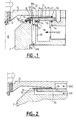
- a pulsating combustion chamber (1) of a gas boiler for example comprises a neck (2) which can have any suitable shape such as that shown in the single figure, or that of the patent application recalled above, said neck (2) having a horizontal surface (3).
- An enclosure filled with water cools the combustion chamber (1).
- a body (5) is fixed to the neck (2) by any fixing means and comprises a bore (6) for the passage of a candle (7) or any other equivalent means for obtaining an explosion of a oxidizer-fuel mixture introduced into the pulsating combustion chamber (1).
- a flexible and elastic valve (9) and a valve seat (10) which is fixed on the neck (2) by means of fixing screws (11), the state-tightness obtained by means of seals (12) provided for this purpose in the body (5) and the neck (2) of the chamber (1 ).
- the valve (9) is in the form of a very light crown made of a sufficiently elastic material so that local deformation can be obtained.
- the seat (10) comprises a number of orifices (13) for the admission of air, which open into an annular groove (13a) and which are distributed circumferentially around the axis of revolution of the seat.
- Other orifices (14) for the admission of gas are also provided in the seat (10) and open into an annular groove (14a).
- the distribution and the number of orifices (13) and (14) are chosen according to the volume of mixture desired in the combustion chamber (1).
- the annular grooves (13a) and (14a) are close to each other so that the air-gas mixture takes place as quickly as possible in the combustion chamber.
- An annular groove (19) is also provided in the seat (10) and has dimensions greater than those of the grooves (13a) and (14a).
- the groove (19) is spaced from the part of the combustion chamber where the mixing takes place so as not to disturb said mixing, while allowing the valve (9) to move upwards as soon as a low pressure occurs. exerts on the face of the valve, intake side, provided that said low pressure is greater than that prevailing in the interval (8) of the combustion chamber (1).
- the orifices (13) and (14) communicate respectively with passages (15) and (16) formed in the neck (2).
- the passage (15) is connected to a source of air while the passage (16) which is in reality an enclosure of a certain volume, is connected to a source of gas.
- the enclosure (16) is separated from the passage (15) by a partition (20).
- the internal face (5a) of the body (5) is slightly inclined from the center towards the periphery so that the gap (8) is smaller towards the right end, in the figure.
- the valve (9) has a small clearance in this reduced area and its displacement travel is consequently reduced.
- valve ( 9) In operation, following the admission of one of the components of the mixture, oxidizer or fuel, or both, into the passages (15) or (16) and the corresponding orifices (13) or (14), the valve ( 9) is lifted substantially vertically until the outer edge (30 g of the valve (9) comes to bear on the internal surface (5a) of the body (5). If necessary, the valve (9), thanks to its elasticity, is liable to deform when the pressure of the component introduced is relatively greater than that prevailing in the space (8). When the pressure prevailing in the combustion chamber (1) increases, after combustion of the mixture, the valve (9) closes very quickly due to the short travel it must travel, and due to the acceleration produced by the effect of its elasticity which acts as a spring. , in the rest state, that is to say that when no pressure is exerted on one of the faces of the valve (9), the latter remains applied against the seat (10).
- the oxidizer-fuel mixture is carried out in a part of the combustion chamber (1).
- the air-gas mixture then takes place in the passage (15) and is introduced into the combustion chamber (1) through the orifice (13).
- Concentric spans (30 to 33) are provided around and between the grooves (13a), (14a), and (19).
- the ranges (31) and (32) are very important because it is between these ranges and the valve that the seal is obtained at the time of the explosions. To reduce leakage as much as possible, these surfaces are produced so that they are in the same horizontal plane, free of scratches or porosity and without the possibility of deformation when the cover is tightened on the valve body.
- the extreme range (30) it must have the same characteristics as the other ranges, but can be located in a slightly lower horizontal plane in order to favor the placing of the valve on the seat. It goes without saying that in no case should the range (30) be higher than the other two (31) to (33).
- the gas inlet is formed in the upper body (5) through a passage (34) which opens into an air supply duct (35) formed in the seat (10) or in any other suitable element, so that the air-gas mixture is carried out in said duct (35) before being introduced into the combustion chamber (1) through the orifice (13).
- valve having suitable physical characteristics in terms of lightness and flexibility in order to obtain the desired deformations.
- a valve with differential rigidity preferably whose rigidity would increase from the center towards the periphery, such rigidity can be obtained either by the shape of the section of the valve, or by the internal nature of the composite material used for the manufacture of said valve.
- the thickness of the valve, at the periphery could be substantially of the same order of magnitude as that of the space provided between the cover (5) and the valve seat (10), on the side of the seat (30).
Landscapes
- Engineering & Computer Science (AREA)
- General Engineering & Computer Science (AREA)
- Mechanical Engineering (AREA)
- Chemical & Material Sciences (AREA)
- Combustion & Propulsion (AREA)
- Fluidized-Bed Combustion And Resonant Combustion (AREA)
- Lift Valve (AREA)
- Feeding And Controlling Fuel (AREA)
- Taps Or Cocks (AREA)
- Check Valves (AREA)
- Mechanically-Actuated Valves (AREA)
Claims (5)
Priority Applications (1)
| Application Number | Priority Date | Filing Date | Title |
|---|---|---|---|
| AT87400719T ATE55475T1 (de) | 1986-04-04 | 1987-04-01 | Gasheizkessel mit schwingender verbrennung. |
Applications Claiming Priority (2)
| Application Number | Priority Date | Filing Date | Title |
|---|---|---|---|
| FR8604834A FR2596854B1 (fr) | 1986-04-04 | 1986-04-04 | Vanne a clapet unique pour chaudiere a gaz |
| FR8604834 | 1986-04-04 |
Publications (2)
| Publication Number | Publication Date |
|---|---|
| EP0240429A1 EP0240429A1 (de) | 1987-10-07 |
| EP0240429B1 true EP0240429B1 (de) | 1990-08-08 |
Family
ID=9333892
Family Applications (1)
| Application Number | Title | Priority Date | Filing Date |
|---|---|---|---|
| EP87400719A Expired - Lifetime EP0240429B1 (de) | 1986-04-04 | 1987-04-01 | Gasheizkessel mit schwingender Verbrennung |
Country Status (14)
| Country | Link |
|---|---|
| US (1) | US4795340A (de) |
| EP (1) | EP0240429B1 (de) |
| JP (1) | JPH01500925A (de) |
| KR (1) | KR880701354A (de) |
| AT (1) | ATE55475T1 (de) |
| AU (1) | AU594143B2 (de) |
| CA (1) | CA1289863C (de) |
| DE (1) | DE3764137D1 (de) |
| ES (1) | ES2016852B3 (de) |
| FR (1) | FR2596854B1 (de) |
| GR (1) | GR3000797T3 (de) |
| MA (1) | MA20939A1 (de) |
| TN (1) | TNSN87047A1 (de) |
| WO (1) | WO1987005987A1 (de) |
Families Citing this family (2)
| Publication number | Priority date | Publication date | Assignee | Title |
|---|---|---|---|---|
| EP2411328B1 (de) | 2009-03-26 | 2019-07-24 | Northeastern University | Kohlenstoffnanostrukturen aus der pyrolyse organischer materialien |
| US9664382B2 (en) | 2010-12-03 | 2017-05-30 | Northeastern University | Method and device for fuel and power generation by clean combustion of organic waste material |
Family Cites Families (4)
| Publication number | Priority date | Publication date | Assignee | Title |
|---|---|---|---|---|
| US2701950A (en) * | 1952-07-26 | 1955-02-15 | Swingfire Bahamas Ltd | Combustion device and check valve therefor |
| US3286728A (en) * | 1963-03-27 | 1966-11-22 | Outboard Marine Corp | Slot type reed valve |
| SE435098B (sv) * | 1982-12-30 | 1984-09-03 | Mareck Bv | Backventil i luftinloppet till en pulsbrennare |
| JPS60160315U (ja) * | 1984-03-30 | 1985-10-24 | 株式会社東芝 | パルス燃焼装置 |
-
1986
- 1986-04-04 FR FR8604834A patent/FR2596854B1/fr not_active Expired - Lifetime
-
1987
- 1987-04-01 EP EP87400719A patent/EP0240429B1/de not_active Expired - Lifetime
- 1987-04-01 WO PCT/FR1987/000105 patent/WO1987005987A1/fr not_active Ceased
- 1987-04-01 US US07/141,601 patent/US4795340A/en not_active Expired - Fee Related
- 1987-04-01 AT AT87400719T patent/ATE55475T1/de not_active IP Right Cessation
- 1987-04-01 ES ES87400719T patent/ES2016852B3/es not_active Expired - Lifetime
- 1987-04-01 KR KR1019870701140A patent/KR880701354A/ko not_active Withdrawn
- 1987-04-01 AU AU71671/87A patent/AU594143B2/en not_active Ceased
- 1987-04-01 JP JP62502196A patent/JPH01500925A/ja active Pending
- 1987-04-01 DE DE8787400719T patent/DE3764137D1/de not_active Expired - Lifetime
- 1987-04-03 TN TNTNSN87047A patent/TNSN87047A1/fr unknown
- 1987-04-03 MA MA21176A patent/MA20939A1/fr unknown
- 1987-04-03 CA CA000533744A patent/CA1289863C/fr not_active Expired - Fee Related
-
1990
- 1990-09-14 GR GR90400652T patent/GR3000797T3/el unknown
Also Published As
| Publication number | Publication date |
|---|---|
| GR3000797T3 (en) | 1991-10-10 |
| ES2016852B3 (es) | 1990-12-01 |
| AU7167187A (en) | 1987-10-20 |
| ATE55475T1 (de) | 1990-08-15 |
| AU594143B2 (en) | 1990-03-01 |
| FR2596854A1 (fr) | 1987-10-09 |
| MA20939A1 (fr) | 1987-12-31 |
| KR880701354A (ko) | 1988-07-26 |
| TNSN87047A1 (fr) | 1990-01-01 |
| WO1987005987A1 (fr) | 1987-10-08 |
| JPH01500925A (ja) | 1989-03-30 |
| US4795340A (en) | 1989-01-03 |
| DE3764137D1 (de) | 1990-09-13 |
| FR2596854B1 (fr) | 1990-01-26 |
| EP0240429A1 (de) | 1987-10-07 |
| CA1289863C (fr) | 1991-10-01 |
Similar Documents
| Publication | Publication Date | Title |
|---|---|---|
| EP2964933B1 (de) | Kompakte dosierungsvorrichtung für einen injektor mit zwei brennstoffkreisläufen für eine flugzeugturbomaschine | |
| FR2591668A1 (fr) | Ajutage d'injection de combustible pour moteur a combustion interne et moteur equipe d'un tel ajutage | |
| FR2972666A1 (fr) | Outil de scellement a gaz a perte de combustible limitee | |
| FR2605358A1 (fr) | Procede pour diminuer un bouchon de vapeur resultant d'une haute temperature dans des moteurs a turbines a gaz | |
| EP0222654B1 (de) | Strahltriebwerk mit Nachverbrennung und radial angeordneten einzelnen Injektoren | |
| EP0240429B1 (de) | Gasheizkessel mit schwingender Verbrennung | |
| FR2856467A1 (fr) | Chambre de combustion annulaire de turbomachine | |
| EP3530908B1 (de) | Brennkammer, die zwei typen von injektoren umfasst, in denen die dichtungsorgane eine unterschiedliche öffnungsschwelle besitzen | |
| FR2534976A1 (fr) | Injecteur de combustible | |
| EP2143929B1 (de) | Raketentriebwerk umfassend eine Einspritzvorrichtung für Monergol mit modulierbarem Durchfluss und stabiler Einspritzgeschwindigkeit | |
| FR2806445A1 (fr) | Procede pour former un melange carburant-air inflammable | |
| EP0653603B1 (de) | Vorrichtung zum gleichzeitigen Ausstossen von zwei Flüssigkeiten, insbesondere pyrotechnischen Flüssigkeiten | |
| FR2461116A1 (fr) | Appareil d'alimentation en combustible pour moteur a explosion | |
| FR2780489A1 (fr) | Perfectionnement aux bruleurs comportant au moins trois conduits d'alimentation en air, dont deux axial et en rotation, concentriques avec au moins une alimentation-en combustible, et un stabilisateur central | |
| CA2180501C (fr) | Statoreacteur pour aeronef a vol supersonique et/ou hypersonique | |
| FR2690977A1 (fr) | Chambre de combustion comportant des passages réglables d'admission de comburant primaire. | |
| EP0604263B1 (de) | Stellglied zur Bewegung einer schwenkbaren Raketendüse | |
| EP3181296B1 (de) | Gasfixierungswerkzeug mit einer brennkammer | |
| EP0161954B1 (de) | Zwischenkanal für eine Vorrichtung zur Brennstoff- und Brennmittelzufuhr von einer mit pulsierender Verbrennung arbeitenden Brennkammer | |
| FR2627228A1 (fr) | Systeme d'injection de carburant pour moteur a deux temps a plusieurs cylindres | |
| FR2504600A1 (fr) | Injecteur de carburant | |
| FR2933743A1 (fr) | Dispositif d'injection de biergol a debit modulable. | |
| FR3146493A1 (fr) | Ensemble pour turbomachine et turbomachine associee | |
| FR2475143A1 (fr) | Injecteur de combustible | |
| FR3071550A1 (fr) | Chambre annulaire de combustion |
Legal Events
| Date | Code | Title | Description |
|---|---|---|---|
| PUAI | Public reference made under article 153(3) epc to a published international application that has entered the european phase |
Free format text: ORIGINAL CODE: 0009012 |
|
| AK | Designated contracting states |
Kind code of ref document: A1 Designated state(s): AT BE CH DE ES GB GR IT LI LU NL SE |
|
| 17P | Request for examination filed |
Effective date: 19871022 |
|
| 17Q | First examination report despatched |
Effective date: 19890118 |
|
| GRAA | (expected) grant |
Free format text: ORIGINAL CODE: 0009210 |
|
| AK | Designated contracting states |
Kind code of ref document: B1 Designated state(s): AT BE CH DE ES GB GR IT LI LU NL SE |
|
| REF | Corresponds to: |
Ref document number: 55475 Country of ref document: AT Date of ref document: 19900815 Kind code of ref document: T |
|
| ITF | It: translation for a ep patent filed | ||
| GBT | Gb: translation of ep patent filed (gb section 77(6)(a)/1977) | ||
| REF | Corresponds to: |
Ref document number: 3764137 Country of ref document: DE Date of ref document: 19900913 |
|
| REG | Reference to a national code |
Ref country code: GR Ref legal event code: FG4A Free format text: 3000797 |
|
| PGFP | Annual fee paid to national office [announced via postgrant information from national office to epo] |
Ref country code: ES Payment date: 19910201 Year of fee payment: 5 |
|
| PGFP | Annual fee paid to national office [announced via postgrant information from national office to epo] |
Ref country code: CH Payment date: 19910318 Year of fee payment: 5 |
|
| PGFP | Annual fee paid to national office [announced via postgrant information from national office to epo] |
Ref country code: LU Payment date: 19910328 Year of fee payment: 5 |
|
| PLBE | No opposition filed within time limit |
Free format text: ORIGINAL CODE: 0009261 |
|
| STAA | Information on the status of an ep patent application or granted ep patent |
Free format text: STATUS: NO OPPOSITION FILED WITHIN TIME LIMIT |
|
| EPTA | Lu: last paid annual fee | ||
| 26N | No opposition filed | ||
| PG25 | Lapsed in a contracting state [announced via postgrant information from national office to epo] |
Ref country code: LU Free format text: LAPSE BECAUSE OF NON-PAYMENT OF DUE FEES Effective date: 19920401 |
|
| PG25 | Lapsed in a contracting state [announced via postgrant information from national office to epo] |
Ref country code: ES Free format text: LAPSE BECAUSE OF NON-PAYMENT OF DUE FEES Effective date: 19920402 |
|
| ITTA | It: last paid annual fee | ||
| PG25 | Lapsed in a contracting state [announced via postgrant information from national office to epo] |
Ref country code: LI Effective date: 19920430 Ref country code: CH Effective date: 19920430 |
|
| REG | Reference to a national code |
Ref country code: CH Ref legal event code: PL |
|
| EAL | Se: european patent in force in sweden |
Ref document number: 87400719.8 |
|
| REG | Reference to a national code |
Ref country code: ES Ref legal event code: FD2A Effective date: 19990201 |
|
| REG | Reference to a national code |
Ref country code: GB Ref legal event code: IF02 |
|
| PGFP | Annual fee paid to national office [announced via postgrant information from national office to epo] |
Ref country code: GB Payment date: 20060421 Year of fee payment: 20 |
|
| PGFP | Annual fee paid to national office [announced via postgrant information from national office to epo] |
Ref country code: AT Payment date: 20060427 Year of fee payment: 20 |
|
| PGFP | Annual fee paid to national office [announced via postgrant information from national office to epo] |
Ref country code: SE Payment date: 20060428 Year of fee payment: 20 Ref country code: GR Payment date: 20060428 Year of fee payment: 20 |
|
| PGFP | Annual fee paid to national office [announced via postgrant information from national office to epo] |
Ref country code: NL Payment date: 20060429 Year of fee payment: 20 |
|
| PGFP | Annual fee paid to national office [announced via postgrant information from national office to epo] |
Ref country code: IT Payment date: 20060430 Year of fee payment: 20 |
|
| PGFP | Annual fee paid to national office [announced via postgrant information from national office to epo] |
Ref country code: DE Payment date: 20060502 Year of fee payment: 20 |
|
| PGFP | Annual fee paid to national office [announced via postgrant information from national office to epo] |
Ref country code: BE Payment date: 20060509 Year of fee payment: 20 |
|
| PG25 | Lapsed in a contracting state [announced via postgrant information from national office to epo] |
Ref country code: GB Free format text: LAPSE BECAUSE OF EXPIRATION OF PROTECTION Effective date: 20070331 |
|
| PG25 | Lapsed in a contracting state [announced via postgrant information from national office to epo] |
Ref country code: NL Free format text: LAPSE BECAUSE OF EXPIRATION OF PROTECTION Effective date: 20070401 |
|
| REG | Reference to a national code |
Ref country code: GB Ref legal event code: PE20 |
|
| NLV7 | Nl: ceased due to reaching the maximum lifetime of a patent |
Effective date: 20070401 |
|
| EUG | Se: european patent has lapsed | ||
| BE20 | Be: patent expired |
Owner name: *MARECK B.V. Effective date: 20070401 Owner name: SOC. NATIONALE *ELF AQUITAINE Effective date: 20070401 |