EP0240150A2 - Workpiece position control - Google Patents
Workpiece position control Download PDFInfo
- Publication number
- EP0240150A2 EP0240150A2 EP87301711A EP87301711A EP0240150A2 EP 0240150 A2 EP0240150 A2 EP 0240150A2 EP 87301711 A EP87301711 A EP 87301711A EP 87301711 A EP87301711 A EP 87301711A EP 0240150 A2 EP0240150 A2 EP 0240150A2
- Authority
- EP
- European Patent Office
- Prior art keywords
- workpiece
- drive means
- turntable
- levelling
- axis
- Prior art date
- Legal status (The legal status is an assumption and is not a legal conclusion. Google has not performed a legal analysis and makes no representation as to the accuracy of the status listed.)
- Granted
Links
Images


Classifications
-
- B—PERFORMING OPERATIONS; TRANSPORTING
- B23—MACHINE TOOLS; METAL-WORKING NOT OTHERWISE PROVIDED FOR
- B23Q—DETAILS, COMPONENTS, OR ACCESSORIES FOR MACHINE TOOLS, e.g. ARRANGEMENTS FOR COPYING OR CONTROLLING; MACHINE TOOLS IN GENERAL CHARACTERISED BY THE CONSTRUCTION OF PARTICULAR DETAILS OR COMPONENTS; COMBINATIONS OR ASSOCIATIONS OF METAL-WORKING MACHINES, NOT DIRECTED TO A PARTICULAR RESULT
- B23Q1/00—Members which are comprised in the general build-up of a form of machine, particularly relatively large fixed members
- B23Q1/25—Movable or adjustable work or tool supports
- B23Q1/44—Movable or adjustable work or tool supports using particular mechanisms
- B23Q1/50—Movable or adjustable work or tool supports using particular mechanisms with rotating pairs only, the rotating pairs being the first two elements of the mechanism
- B23Q1/54—Movable or adjustable work or tool supports using particular mechanisms with rotating pairs only, the rotating pairs being the first two elements of the mechanism two rotating pairs only
- B23Q1/545—Movable or adjustable work or tool supports using particular mechanisms with rotating pairs only, the rotating pairs being the first two elements of the mechanism two rotating pairs only comprising spherical surfaces
- B23Q1/5462—Movable or adjustable work or tool supports using particular mechanisms with rotating pairs only, the rotating pairs being the first two elements of the mechanism two rotating pairs only comprising spherical surfaces with one supplementary sliding pair
-
- G—PHYSICS
- G01—MEASURING; TESTING
- G01B—MEASURING LENGTH, THICKNESS OR SIMILAR LINEAR DIMENSIONS; MEASURING ANGLES; MEASURING AREAS; MEASURING IRREGULARITIES OF SURFACES OR CONTOURS
- G01B5/00—Measuring arrangements characterised by the use of mechanical techniques
- G01B5/0002—Arrangements for supporting, fixing or guiding the measuring instrument or the object to be measured
- G01B5/0004—Supports
-
- G—PHYSICS
- G01—MEASURING; TESTING
- G01B—MEASURING LENGTH, THICKNESS OR SIMILAR LINEAR DIMENSIONS; MEASURING ANGLES; MEASURING AREAS; MEASURING IRREGULARITIES OF SURFACES OR CONTOURS
- G01B7/00—Measuring arrangements characterised by the use of electric or magnetic techniques
- G01B7/28—Measuring arrangements characterised by the use of electric or magnetic techniques for measuring contours or curvatures
- G01B7/282—Measuring arrangements characterised by the use of electric or magnetic techniques for measuring contours or curvatures for measuring roundness
Definitions
- This invention relates to workpiece position control and is particularly concerned with a method and apparatus for centring and levelling a workpiece on a turntable, especially in metrological apparatus.
- Metrological apparatus in which a workpiece is positioned on a turntable and measurements are taken by rotating the turntable whilst a transducer senses the surface of the workpiece. It is generally necessary to perform an operation known as centring and levelling in which the turntable is displaced horizontally and is tilted to bring the workpiece to a desired position, typically in order to bring a required axis of the workpiece into coincidence with the rotary axis of the turntable. Further, it is highly desirable that the centring and levelling operation should be performed automatically so that it may be carried out efficiently and quickly.
- the turntable which is circular, is mounted on a support structure which includes a spherical bearing surface permitting universal tilting movement of the turntable about a point which is above the work surface of the turntable and is in a known horizontal plane.
- Two jacks located beneath the turntable at positions spaced apart by 90 degrees from each other are provided for effecting the tilting movement about respective orthogonal axes located in the above mentioned horizontal plane.
- Springs urge the turntable downwardly to maintain it in engagement with the jacks and to maintain the spherical bearing surface in engagement with a mating seating which in one construction comprises a ring of balls set in the support structure.
- the support structure is mounted on a spindle for rotating the turntable, by means of a further bearing providing for horizontal movement of the support structure whereby the centring operation may be performed.
- centring and levelling is carried out, after the workpiece to be tested has been placed on the turntable, by firstly determining the location of the centre of that portion of the workpiece surface located in the horizontal plane containing the point about which the turntable is tiltable. This determination is made by bringing a stylus included in the apparatus into contact with the workpiece surface in this horizontal plane and driving the spindle to rotate the workpiece about the spindle axis. The degree of eccentricity between the axis of rotation of the workpiece (or axis of the spindle) and the position of the centre of the workpiece surface in this plane can then be determined from the signals output by a transducer with which the stylus is associated.
- the support structure for the turntable is displaced horizontally relative to the spindle in order to bring the determined centre of the workpiece surface into coincidence with the axis of the spindle.
- the centring operation is completed for that plane.
- Levelling is performed by moving the stylus to a different horizontal plane, driving the spindle to rotate the workpiece, and determining the eccentricity of the centre of the workpiece surface in this horizontal plane with respect to the spindle axis utilising the signals output by the transducer. After this eccentricity has been determined, the jacks are actuated as necessary to bring the centre of the workpiece surface in the second horizontal plane into coincidence with the axis of rotation of the turntable (the spindle axis). This completes the levelling operation and thus centring and levelling is complete.
- the invention provides an apparatus in which one or more of these problems may be eliminated.
- the invention provides a workpiece positioning apparatus having a turntable for supporting the workpiece and computer means which is operable to perform a centring and levelling operation in which any decentring of the workpiece arising as a consequence of tilting of the turntable for levelling purposes is compensated for.
- the centring and levelling may be performed with reference to any horizontal planes, without being restricted to the unique horizontal plane containing the centre of tilting of the turntable as in the above described prior art.
- the invention provides workpiece positioning apparatus having a turntable for the workpiece, the turntable being supported at three points located at the apices of a triangle, preferably an equilateral triangle, within which the centre of the turntable is located, at least two of said points being adjustable in height, and computer means for performing a centring and levelling operation in which adjustment of the height of one or more of said points takes place.
- the invention provides a method or apparatus for performing a centring and/or levelling operation in which the workpiece is sensed by sensing means and the operation is performed under the control of electronic control means in accordance with a predetermined algorithm.
- the present invention provides apparatus having a turntable for supporting a workpiece, the turntable being pivotal about a point or axes beIow the surface thereof for effecting levelling, and electronic control means being provided for effecting said pivotal movement.
- the point or intersection of the axes is preferably offset from the axis of rotation of the turntable.
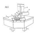
- a metrological apparatus comprises a work bench 2 supported by a frame 3 (whose feet only are visible in Figure 1).
- the frame 3 carries a turntable 4 on which a workpiece may be mounted.
- a vertical column 6 supports a motor-driven vertically movable carriage 8.
- a stylus 10 is mounted on the end of a pivotaI arm 12, which enables the attitude of the stylus to be changed, which in turn is carried on the end of a horizontally (radially) movable arm 14 supported by the carriage 8.
- Measuring operations on a workpiece are performed by causing the stylus 10 to traverse the surface of the workpiece by rotating the turntable and/or moving the stylus radially and/or moving the stylus vertically.
- the support structure for the turntable 4 includes a base 16 carried by a disc 18 which is secured to a motor driven spindle 20.
- the bearing arrangement 21 is mounted in the frame 3 and is preferably as described in our UK Published Patent Application No. 2178805A.
- a set of ball bearings 22 in a disc shaped cage 24 is interposed between the base 16 and the disc 18 to provide for horizontal movement of the base 16 relative to the disc 18.
- This movement is effected along orthogonal x and y axes by means of motors 26x, 26y which are fixed on the base 16 and respectively drive reciprocable drive rods 28x and 28y via gear boxes 30x and 30y which may, for example, comprise worm and wheel assemblies.
- the drive rods 28x and 28y are driven respectively along the x and y axes when the respective motors are actuated.
- a boss 32 which is fixed to the upper end of the spindle 20, which projects through a central opening 34 in the base 16, has flats 32x and 32y which are engaged respectively by the ends of the drive rods 28x and 28y and are located, respectively, in planes which are perpendicular to the x and y axes.
- a tension spring 36 having one end connected to the boss 32 and the other end connected to a post 38, which is fixed to the base 16, maintains the flats 32x and 32y in engagement with the ends of the respective drive rods 28x and 28y.
- the base 16 may be moved accurately determined distances in either direction along the x and y axes.
- Guide plates 40x and 40y through which the drive rods 28x and 28y pass respectively, have slots 42 receiving guide pins 44 carried by the gear boxes 30x and 30y.
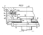
- a ball 46 mounted in a recess in the upper end of the post 38 supports the turntable 4 for universal pivotal movement about the point P.
- the turntable 4 is supported respectively on balls 50a and 50b via spacers 52 (Fig. 3 only) which are fixed to the underside of the turntable 4 and rest on the balls 50a, 50b.
- Lever plates 54a, 54b, mounted on brackets 56 for pivotal movement about horizontal axes 58 (perpendicular to the plane of the paper of Fig. 3) contain depressions 60a, 60b in which the balls 50a, 50b are respectively received.
- Motors 62a, 62b drive jacks 64a, 64b (Fig. 3 only) through gear boxes 66a, 66b for pivoting the lever plates 54a, 54b upwardly and downwardly about their pivotal axis 58.
- actuation of the motor 62a causes the turntable to tilt about an axis joining points P and B and actuation of the motor 62b causes the turntable 4 to tilt about an axis joining the points P and A.
- These axes pass through the centres of the balls 46, 50a and 50b.
- the points ABP are located at the apices of an equilateral triangle whose centre C is coincident with the centre of the turntable 4 i.e. the points ABP are symmetrically disposed relative to the point C. This provides the maximum area of the turntable within which a workpiece may be located without causing instability of the turntable. As a result, however, the axes PA and PB about which the turntable is tiltable are at 60 degrees to each other.
- Tension springs 68 urge the turntable downwardly to maintain the spacers 52 in engagement with the balls 50a and 50b and tension springs 70 urge the lever plates 54a and 54b downwardly to maintain them in engagement with the jacks 64a, 64b.
- a cylindrical wall 69 fixed to the disc 18 encloses the support structure above described.
- motors 26x, 26y, for centring, and motors 62a, 62b, for levelling are controlled by a computer system 72 which receives inputs from a transducer 73 which responds to the stylus 10.
- An operator controlled keyboard 75 is provided for supplying instructions to the computer system 72.
- the computer system 72 also controls a motor 74 which drives the spindle 20 for rotating the turntable (the 0 axis), a motor 76 for raising and lowering the carriage 8 on the column 6 (z axis), and a motor 78 which drives the arm 14 in the radial direction (the r axis) for bringing the stylus 10 into and out of contact with the workpiece surface.
- Further transducers 80, 82 and 84 provide the computer system 72 with data representative of the angular position of the turntable 4, the vertical position of the carriage 8 and the radial position of the arm 14.
- a VDU 86 and memory 88 are also connected to the computer system 72, the memory 88 storing the received data and storing programs in accordance with which the computer system 72 operates.
- the computer system 72 may comprise one or more computers.
- Fig. 5 illustrates a cylindrical workpiece 100 positioned on the turntable 4, within the triangle ABP.
- the workpiece 100 stands on one end 102 which is plane but assumed to be at a slight angle (much exaggerated in Fig. 5) to the radial plane, so that the axis 104 of the workpiece 100 is at an angle to the vertical axis of rotation 23 of the spindle 20.
- the computer system 72 receives the output from the transducers (80, 73, 84) and, utilising a form fitting algorithm, computes the magnitude and direction of the displacement between the centre 110 of the workpiece in plane 108 and the axis 23.
- the polar parameters output by the transducers are transformed to a notional cartesian system (u,v), and given that N points are sensed on the surface having coordinates (u i ,v i ), the centre (u o ,v o ) and radius R of the surface are calculated using a modified least squares error criterion by minimising the sum: [(u i -u o )2 + (v i - v o )2 - R2]2 Having computed the centre, the computer then actuates motors 26x and 26y as necessary to bring point 110 into concidence with the axis 23 as shown in Fig. 5b.
- the next step is for the turntable 4 to be rotated with the stylus 10 arranged to sense the surface of the workpiece in a different horizontal plane 112 spaced from the plane 108, in this example plane 112 being above plane 108.
- the computer system 72 determines the position of the centre of the workpiece in the plane 112.
- the computer system 72 computes the angular movement of the turntable 4 and workpiece 100 necessary to bring the workpiece from the position shown in Fig. 5b to the position shown in Fig. 5c in which the axis 104 of the workpiece is parallel to the axis 23 of the spindle. This computation will be described further below. As can be seen in Fig.
- the result of this angular movement or tilting is that point 110 again becomes displaced from the axis 23.
- the final step is the performance of a second centring operation in which the position of the axis 104 of the workpiece relative to the axis 23 is determined utilising again the form fitting algorithm mentioned above and the motors 26x and 26y are again actuated, in order to bring the axis 104 into coincidence with the axis 23 as shown in Fig. 5d.
- centring and levelling may be achieved by firstly taking measurements in the planes 110 and 112 with the workpiece 100 and turntable 4 in the position shown in Fig. 5a and thereafter, motors 26x and 26y and 62a and 62b are actuated simultaneously or in any desired sequence, but preferably in the order to centre the workpiece and then level it, in order to achieve the condition shown in Fig. 5d.
- motors 26x and 26y will be referred to as the x and y motors and motors 62a and 62b will be referred to as the a and b motors.
- the component may have any form provided that the surfaces being assessed have a regular profile it will be convenient to consider the case of centring and levelling a cylindrical workpiece such as the workpiece 100 shown in Fig. 5, since the axis of a cylinder is readily defined.
- Centring of the table is achieved by resolving the required motion in terms of the X and Y axes into motions parallel to the line of action of the x and y motors.
- the distance between the axis 58 and the centre 51 of the ball bearing 50a or 50b is 12 millimetres and between the axis 58 and the point of contact 55 of the jack 64a or 64b with the lever 54a or 54b is 36 millimetres.
- the number of revolutions of the a and b motors required to achieve levelling can be easily determined utilising the above calculations. Further, the number of revolutions of the x and y motors required to achieve centring is also easily calculated. Both calculations are performed by the computer system 72 and the results utilised drive the a, b, x and y motors.
- the illustrated embodiment possesses the substantial advantages that the planes 108 and 112 shown in Fig. 5 at which the surface of the workpiece is measured for centring and levelling purposes may be located anywhere within the range of operation of the transducers 73 and 84; the workpiece may be positioned with its centre of mass anywhere within the triangle ABP, which is substantially larger than the corresponding area in prior art apparatus and, being symmetrical about the centre of the turntable, is much more conveniently located; and since the turntable is supported at three points, two of which are of adjustable height for providing tilting movement for levelling purposes, the need for expensive large spherical bearings as in the prior art is eliminated.
- the apparatus described has the combined advantage that the centring and levelling operation can be carried out automatically, that the mechanical construction of the turntable and its drive means may be relatively simple, that the turntable has a high degree of stability, and that there is greater diversity of the types of workpieces which can be assessed.
- the aspect of the invention concerned with making measurements at planes spaced from the centre or axes of tilt may be applied to a metrological apparatus in which the workpiece is not supported on a worktable, but rather is held in a chuck or the like which may be rotated about an axis other than a vertical axis, for example a horizontal axis.
- the invention is not confined to sensing external surfaces of the workpiece (such as the bearing surfaces of a crankshaft), but is also applicable when internal surfaces (such as the input and output bearing seatings of a gearbox housing) are to be detected.
- an engine piston may desirably be centred and levelled by centring the piston crown and setting the lower edge of the piston skirt at right angles to the axis.
- the inclination of a second portion of the workpiece, or a reference surface stationary thereto is determined. Then, the determined centre can be centred; and then the inclination can be adjusted; and then the centre can be recentred in compensation for any decentring arising from the inclination adjustment.
- the invention is not restricted to use with workpieces having circular portions to be sensed, but can be used with workpieces having sections of other shapes, such as rectangular, triangular, elliptical and hexagonal shapes, to be sensed.
- the sensor can be tracked along a helical path relative to the workpiece surface and the amounts of transverse and tilt adjustment can then be determined.
- the arrangement of the transducer 10, the support structure 12, 14 thereof and the cotrol system shown in Figure 4 are all as described in our copending application filed simultaneously herewith, claiming priority from British Patent Application No. 8605324 filed 04 March 1986 and naming Hugh Rogers Lane and Peter Dean Onyon as inventors.
- a high resolution transducer having a small range of operation is mounted on a radially movable arm which is motor driven under computer control in response to the output of the transducer so that the transducer may automatically follow a workpiece surface having large variations of form.
- the transducer may have a resolution to about 12 nanometres over a range of about 0.4 mm and the radially movable arm may have a range of movement of about 200 mm and be provided with a position sensing systems with a resolution of about 200 nanometres.
- This arrangement simplifies the centring and levelling operation in that accurate prepositioning of the workpiece on the turntable by eye is not needed since the transducer system of our aforesaid copending application can accommodate any centring and levelling errors within the range of the available centring and levelling adjustments of the turntable.
Landscapes
- Physics & Mathematics (AREA)
- General Physics & Mathematics (AREA)
- Engineering & Computer Science (AREA)
- Mechanical Engineering (AREA)
- Machine Tool Units (AREA)
Abstract
Description
- This invention relates to workpiece position control and is particularly concerned with a method and apparatus for centring and levelling a workpiece on a turntable, especially in metrological apparatus.
- Metrological apparatus is known in which a workpiece is positioned on a turntable and measurements are taken by rotating the turntable whilst a transducer senses the surface of the workpiece. It is generally necessary to perform an operation known as centring and levelling in which the turntable is displaced horizontally and is tilted to bring the workpiece to a desired position, typically in order to bring a required axis of the workpiece into coincidence with the rotary axis of the turntable. Further, it is highly desirable that the centring and levelling operation should be performed automatically so that it may be carried out efficiently and quickly.
- Metrological apparatus in which centring and levelling may be performed automatically is already known and commercially available. In the known apparatus, the turntable, which is circular, is mounted on a support structure which includes a spherical bearing surface permitting universal tilting movement of the turntable about a point which is above the work surface of the turntable and is in a known horizontal plane. Two jacks located beneath the turntable at positions spaced apart by 90 degrees from each other are provided for effecting the tilting movement about respective orthogonal axes located in the above mentioned horizontal plane. Springs urge the turntable downwardly to maintain it in engagement with the jacks and to maintain the spherical bearing surface in engagement with a mating seating which in one construction comprises a ring of balls set in the support structure. The support structure is mounted on a spindle for rotating the turntable, by means of a further bearing providing for horizontal movement of the support structure whereby the centring operation may be performed.
- In this prior art apparatus, centring and levelling is carried out, after the workpiece to be tested has been placed on the turntable, by firstly determining the location of the centre of that portion of the workpiece surface located in the horizontal plane containing the point about which the turntable is tiltable. This determination is made by bringing a stylus included in the apparatus into contact with the workpiece surface in this horizontal plane and driving the spindle to rotate the workpiece about the spindle axis. The degree of eccentricity between the axis of rotation of the workpiece (or axis of the spindle) and the position of the centre of the workpiece surface in this plane can then be determined from the signals output by a transducer with which the stylus is associated. Thereafter, the support structure for the turntable is displaced horizontally relative to the spindle in order to bring the determined centre of the workpiece surface into coincidence with the axis of the spindle. Thus, the centring operation is completed for that plane. Levelling is performed by moving the stylus to a different horizontal plane, driving the spindle to rotate the workpiece, and determining the eccentricity of the centre of the workpiece surface in this horizontal plane with respect to the spindle axis utilising the signals output by the transducer. After this eccentricity has been determined, the jacks are actuated as necessary to bring the centre of the workpiece surface in the second horizontal plane into coincidence with the axis of rotation of the turntable (the spindle axis). This completes the levelling operation and thus centring and levelling is complete.
- Since the tilting movement of the turntable which takes place during this levelling operation is centred at a point in the first horizontal plane, which point has been made coincident with the spindle axis by means of the centring operation, the levelling operation does not upset this coincidence.
- This apparatus suffers from a number of disadvantages. Firstly, every centring operation has to be performed by sensing the workpiece surface located in the same, fixed horizontal plane containing the centre of tilting of the turntable, and in some cases a workpiece will not have a surface in that plane which can be sensed. This is a severe disadvantage with workpieces of complex shape, such as crank shafts. Second, the centre of mass of the workpiece must always be located within the 90 degree sector of the turntable defined by the positions of the two jacks: locating the centre of mass outside this sector would produce a turning moment on the turntable tending to move the turntable out of contact with these jacks. Thirdly, manufacture of the spherical bearing which supports the turntable to the required degree of accuracy is difficult and expensive.
- The invention provides an apparatus in which one or more of these problems may be eliminated.
- In one aspect, the invention provides a workpiece positioning apparatus having a turntable for supporting the workpiece and computer means which is operable to perform a centring and levelling operation in which any decentring of the workpiece arising as a consequence of tilting of the turntable for levelling purposes is compensated for. Thus, with the apparatus constructed in accordance with this aspect of the invention, the centring and levelling may be performed with reference to any horizontal planes, without being restricted to the unique horizontal plane containing the centre of tilting of the turntable as in the above described prior art.
- In another aspect, the invention provides workpiece positioning apparatus having a turntable for the workpiece, the turntable being supported at three points located at the apices of a triangle, preferably an equilateral triangle, within which the centre of the turntable is located, at least two of said points being adjustable in height, and computer means for performing a centring and levelling operation in which adjustment of the height of one or more of said points takes place.
- In a further aspect the invention provides a method or apparatus for performing a centring and/or levelling operation in which the workpiece is sensed by sensing means and the operation is performed under the control of electronic control means in accordance with a predetermined algorithm.
- In another aspect, the present invention provides apparatus having a turntable for supporting a workpiece, the turntable being pivotal about a point or axes beIow the surface thereof for effecting levelling, and electronic control means being provided for effecting said pivotal movement. The point or intersection of the axes is preferably offset from the axis of rotation of the turntable.
- Other aspects of the invention will be apparent from the following description and claims.
- The invention is described further by way of example with reference to the accompanying drawings in which:
- Fig. 1 is a perspective view of an apparatus embodying the invention;
- Fig. 2 is a perspective view of a turntable support structure included in the apparatus of Fig. 1;
- Fig. 3 is a section through part of the support structure of Fig. 2, but showing also the turntable;
- Fig. 4 is a simplified block diagram of a control system included in the apparatus of Fig. 1;
- Figs. 5a to 5d diagrammatically illustrate a centring and levelling operation; and
- Figs. 6 to 9 are diagrams for assisting in understanding the computations performed by the control system for carrying out the centring and levelling operation illustrated in Fig. 6.
- With reference to Fig. 1, a metrological apparatus comprises a
work bench 2 supported by a frame 3 (whose feet only are visible in Figure 1). Theframe 3 carries aturntable 4 on which a workpiece may be mounted. Avertical column 6 supports a motor-driven verticallymovable carriage 8. Astylus 10 is mounted on the end of apivotaI arm 12, which enables the attitude of the stylus to be changed, which in turn is carried on the end of a horizontally (radially)movable arm 14 supported by thecarriage 8. Measuring operations on a workpiece are performed by causing thestylus 10 to traverse the surface of the workpiece by rotating the turntable and/or moving the stylus radially and/or moving the stylus vertically. - As shown in Figs. 2 and 3, the support structure for the
turntable 4 includes abase 16 carried by adisc 18 which is secured to a motor drivenspindle 20. Abearing arrangement 21, indicated diagrammatically in Figure 3 by broken lines, supports thespindle 20 for rotation about itsown axis 23, which is vertical. Thebearing arrangement 21 is mounted in theframe 3 and is preferably as described in our UK Published Patent Application No. 2178805A. A set ofball bearings 22 in a disc shapedcage 24 is interposed between thebase 16 and thedisc 18 to provide for horizontal movement of thebase 16 relative to thedisc 18. This movement is effected along orthogonal x and y axes by means ofmotors base 16 and respectively drivereciprocable drive rods 28x and 28y viagear boxes drive rods 28x and 28y are driven respectively along the x and y axes when the respective motors are actuated. Aboss 32 which is fixed to the upper end of thespindle 20, which projects through acentral opening 34 in thebase 16, hasflats drive rods 28x and 28y and are located, respectively, in planes which are perpendicular to the x and y axes. Atension spring 36 having one end connected to theboss 32 and the other end connected to apost 38, which is fixed to thebase 16, maintains theflats respective drive rods 28x and 28y. Thus, with the aid of themotors spring 36 thebase 16 may be moved accurately determined distances in either direction along the x and y axes.Guide plates 40x and 40y through which the drive rods 28x and 28y pass respectively, haveslots 42receiving guide pins 44 carried by thegear boxes - A
ball 46 mounted in a recess in the upper end of thepost 38 supports theturntable 4 for universal pivotal movement about the point P. - At points A and B, the
turntable 4 is supported respectively onballs turntable 4 and rest on theballs Lever plates brackets 56 for pivotal movement about horizontal axes 58 (perpendicular to the plane of the paper of Fig. 3) containdepressions 60a, 60b in which theballs 62b drive jacks 64a, 64b (Fig. 3 only) throughgear boxes lever plates pivotal axis 58. Thus, actuation of themotor 62a causes the turntable to tilt about an axis joining points P and B and actuation of themotor 62b causes theturntable 4 to tilt about an axis joining the points P and A. These axes pass through the centres of theballs - The points ABP are located at the apices of an equilateral triangle whose centre C is coincident with the centre of the
turntable 4 i.e. the points ABP are symmetrically disposed relative to the point C. This provides the maximum area of the turntable within which a workpiece may be located without causing instability of the turntable. As a result, however, the axes PA and PB about which the turntable is tiltable are at 60 degrees to each other. -
Tension springs 68 urge the turntable downwardly to maintain thespacers 52 in engagement with theballs tension springs 70 urge thelever plates jacks 64a, 64b. - A cylindrical wall 69 fixed to the
disc 18 encloses the support structure above described. - As seen in the simplified block diagram of Fig. 4,
motors motors computer system 72 which receives inputs from atransducer 73 which responds to thestylus 10. An operator controlledkeyboard 75 is provided for supplying instructions to thecomputer system 72. Thecomputer system 72 also controls a motor 74 which drives thespindle 20 for rotating the turntable (the 0 axis), a motor 76 for raising and lowering thecarriage 8 on the column 6 (z axis), and amotor 78 which drives thearm 14 in the radial direction (the r axis) for bringing thestylus 10 into and out of contact with the workpiece surface.Further transducers computer system 72 with data representative of the angular position of theturntable 4, the vertical position of thecarriage 8 and the radial position of thearm 14. AVDU 86 andmemory 88 are also connected to thecomputer system 72, thememory 88 storing the received data and storing programs in accordance with which thecomputer system 72 operates. Thecomputer system 72 may comprise one or more computers. - The movements which the
turntable 4 undergoes to achieve centring and levelling of a workpiece will be understood by reference to Figs. 5a to 5d. For simplicity, Fig. 5 illustrates acylindrical workpiece 100 positioned on theturntable 4, within the triangle ABP. Theworkpiece 100 stands on oneend 102 which is plane but assumed to be at a slight angle (much exaggerated in Fig. 5) to the radial plane, so that theaxis 104 of theworkpiece 100 is at an angle to the vertical axis ofrotation 23 of thespindle 20. The sequence of steps carried out in the centring and levelling operation illustrated in Fig. 5 comprises firstly rotating theturntable 4 with thestylus 10 arranged to sense the surface of theworkpiece 100 in ahorizontal plane 108. Thecomputer system 72 receives the output from the transducers (80, 73, 84) and, utilising a form fitting algorithm, computes the magnitude and direction of the displacement between thecentre 110 of the workpiece inplane 108 and theaxis 23. The polar parameters output by the transducers are transformed to a notional cartesian system (u,v), and given that N points are sensed on the surface having coordinates (ui,vi), the centre (uo,vo) and radius R of the surface are calculated using a modified least squares error criterion by minimising the sum:
[(ui-uo)² + (vi- vo)² - R²]²
Having computed the centre, the computer then actuatesmotors point 110 into concidence with theaxis 23 as shown in Fig. 5b. The next step is for theturntable 4 to be rotated with thestylus 10 arranged to sense the surface of the workpiece in a differenthorizontal plane 112 spaced from theplane 108, in thisexample plane 112 being aboveplane 108. Again utilising the form fitting algorithm, thecomputer system 72 determines the position of the centre of the workpiece in theplane 112. Thereafter, thecomputer system 72 computes the angular movement of theturntable 4 andworkpiece 100 necessary to bring the workpiece from the position shown in Fig. 5b to the position shown in Fig. 5c in which theaxis 104 of the workpiece is parallel to theaxis 23 of the spindle. This computation will be described further below. As can be seen in Fig. 5c, the result of this angular movement or tilting, is thatpoint 110 again becomes displaced from theaxis 23. The final step is the performance of a second centring operation in which the position of theaxis 104 of the workpiece relative to theaxis 23 is determined utilising again the form fitting algorithm mentioned above and themotors axis 104 into coincidence with theaxis 23 as shown in Fig. 5d. Although, for simplicity, the foregoing description of Fig. 5 has been on the basis that the various steps are carried out in a particular sequence, this is not essential and in practice centring and levelling may be achieved by firstly taking measurements in theplanes workpiece 100 andturntable 4 in the position shown in Fig. 5a and thereafter,motors - The calculations of the horizontal and tilting movements required to be effected by the
turntable 4 in order to achieve centring and levelling will now be described. In the following description,motors motors workpiece 100 shown in Fig. 5, since the axis of a cylinder is readily defined. - In the discussions which follow it will be convenient to refer all motions to a right-handed cartesian coordinate system X, Y and Z having unit vectors i, j, k. The origin of the co-ordinate system is chosen to be coincident with the fixed point P, and the X axis is chosen to bisect the line joining the two points A and B. The co-ordinate system is shown in Fig. 6, in which the Z axis is perpendicular to the plane of the paper and is also shown on Fig. 2.
- Centring of the table is achieved by resolving the required motion in terms of the X and Y axes into motions parallel to the line of action of the x and y motors.
- Let the required centring vector be c₁i + c₂j, and let the unit vectors parallel to the lines of action of the x and y motors be ex and ey respectively. From the geometry it may then be seen that..
c₁i + c₂j = -k [(c₁ - c₂)ex + (c₁ + c₂)ey] (1)
wherein k = 2-1/2.
- In discussing the levelling of a component placed on the table it is convenient to introduce two more variables ϑ₁ and ϑ₂ where ϑ₁ is the angle of tilt of the table top about the X axis, and ϑ₂ is the corresponding angle about the Y axis. Thus the height of any point (X₁,Y₁) on the surface of the table, with respect to its height when the surface is horizontal, is given by
Z₁ = X₁tanϑ₁ + Y₁tanϑ₂ (2)
- Now, introducing parameters T₁ and T₂ as shown in Fig. 6 and referring to the incremental heights of points A and B as ZA, ZB, this gives the formulae
ZA = T₁tanϑ₁ + T₂tanϑ₂ (3a)
ZB = T₁tanϑ₁ - T₂tanϑ₂ (3b)
- From these equations it is possible to calculate the incremental heights of A and B, above the horizontal plane through P, in terms of the angles of tilt ϑ₁ and ϑ₂.
- As will be seen from Figure 6, the magnitudes of T₁ and T₂ are dependent upon the angle APB between the axes AP and BP about which the turntable is tiltable. Thus, the calculations performed by the
computer 72 in carrying out the levelling operation are dependent upon the angle APB. - Before proceeding it is necessary to consider further the actual mechanism by which the points A and B are moved in the vertical plane by the a and b motors in the preferred embodiment.
- As shown in Fig. 7 by way of example, the distance between the
axis 58 and thecentre 51 of theball bearing axis 58 and the point ofcontact 55 of thejack 64a or 64b with thelever - Referring to Fig. 8 it can be seen that if the
screw jack 64a or 64b is raised by a height z, then the centre of theball
z = 36tanα (4)
δz= 12sinα
from which
z = 36 δz/(12² - δz²)1/2 (5a)
or
z = 3δz + 3δz³/(2×12²) + 3²δz⁵/(2³×12⁴) + .... (5b)
- Suppose that the table 4 is initially horizontal and that a cylinder is measured at two heights (z₁,z₂), the centres of the two planes being found as (a₁,b₁,z₁) and (a₂,b₂,z₂) as shown in Fig 9. It can be seen that any point at height Z and lying on the cylinder axis will have co-ordinates, in the chosen system, given by
X = [(a₂ - a₁)/(z₂ - z₁)] Z + a₁
Y = [(b₂ - b₁)/(z₂ - z₁)] Z + b₁
- Writing h = (z₂ - z₁), and comparing these equations with equations (2)
tanϑ₁ = (a₂ - a₁)/h
tanϑ₂ = (b₂ - b₁)/h
- The incremental heightsδZA,δZB through which points A and B must be moved in order to compensate for these angles are given by equations (3) as
δZA = T₁tanϑ₁ + T₂tanϑ₂
δZB = T₁tanϑ₁ - T₂tanϑ₂
and from equation (5) the heights through which the screw jacks must be raised are given by
ZA = 3 δZA/(12²- δZA²) 1/2
ZB = 3 δZB/(12² - δZB²)1/2
- Using the binomial expansion of these equations and truncating the series at the second term gives
ZA = 3 δZA + p δZ A³
ZB = 3 δ ZB + p δZ B³
where p = 1.1331161×10⁻² and includes a correction for the truncations of the series. - Thus, the number of revolutions of the a and b motors required to achieve levelling can be easily determined utilising the above calculations. Further, the number of revolutions of the x and y motors required to achieve centring is also easily calculated. Both calculations are performed by the
computer system 72 and the results utilised drive the a, b, x and y motors. - Thus, the illustrated embodiment possesses the substantial advantages that the
planes transducers - The apparatus described has the combined advantage that the centring and levelling operation can be carried out automatically, that the mechanical construction of the turntable and its drive means may be relatively simple, that the turntable has a high degree of stability, and that there is greater diversity of the types of workpieces which can be assessed.
- Furthermore, the aspect of the invention concerned with making measurements at planes spaced from the centre or axes of tilt may be applied to a metrological apparatus in which the workpiece is not supported on a worktable, but rather is held in a chuck or the like which may be rotated about an axis other than a vertical axis, for example a horizontal axis.
- The invention is not confined to sensing external surfaces of the workpiece (such as the bearing surfaces of a crankshaft), but is also applicable when internal surfaces (such as the input and output bearing seatings of a gearbox housing) are to be detected.
- In some instances, rather than aligning the centres of two portions of the workpiece (such as two bearing surfaces of a crankshaft) it is desirable to centre one point of the workpiece on the turntable axis and to level another planar surface of the workpiece by making it orthogonal to the axis. For example, an engine piston may desirably be centred and levelled by centring the piston crown and setting the lower edge of the piston skirt at right angles to the axis. In this case, rather than determining the centre of a second portion of the workpiece, the inclination of a second portion of the workpiece, or a reference surface stationary thereto (such as the turntable surface on which the piston rests), is determined. Then, the determined centre can be centred; and then the inclination can be adjusted; and then the centre can be recentred in compensation for any decentring arising from the inclination adjustment.
- The invention is not restricted to use with workpieces having circular portions to be sensed, but can be used with workpieces having sections of other shapes, such as rectangular, triangular, elliptical and hexagonal shapes, to be sensed.
- In the case where the workpiece is cylindrical, for example, it is not necessary to sense the circular profile of the workpiece in two spaced planes, but instead the sensor can be tracked along a helical path relative to the workpiece surface and the amounts of transverse and tilt adjustment can then be determined.
- Preferably, the arrangement of the
transducer 10, thesupport structure
Claims (17)
Applications Claiming Priority (4)
| Application Number | Priority Date | Filing Date | Title |
|---|---|---|---|
| GB8605325 | 1986-03-04 | ||
| GB868605325A GB8605325D0 (en) | 1986-03-04 | 1986-03-04 | Workpiece position control |
| GB8624396 | 1986-10-10 | ||
| GB08624396A GB2189604A (en) | 1986-03-04 | 1986-10-10 | Workpiece position control |
Publications (3)
| Publication Number | Publication Date |
|---|---|
| EP0240150A2 true EP0240150A2 (en) | 1987-10-07 |
| EP0240150A3 EP0240150A3 (en) | 1988-03-09 |
| EP0240150B1 EP0240150B1 (en) | 1991-04-17 |
Family
ID=26290438
Family Applications (1)
| Application Number | Title | Priority Date | Filing Date |
|---|---|---|---|
| EP87301711A Expired EP0240150B1 (en) | 1986-03-04 | 1987-02-26 | Workpiece position control |
Country Status (4)
| Country | Link |
|---|---|
| US (1) | US4731934A (en) |
| EP (1) | EP0240150B1 (en) |
| DE (1) | DE3769350D1 (en) |
| DK (1) | DK108487A (en) |
Cited By (12)
| Publication number | Priority date | Publication date | Assignee | Title |
|---|---|---|---|---|
| EP0487003A3 (en) * | 1990-11-20 | 1992-10-14 | Canon Kabushiki Kaisha | Slope detection method, and information detection/writing apparatus using the method |
| EP0517270A1 (en) * | 1991-06-05 | 1992-12-09 | Canon Kabushiki Kaisha | Scanning probe microscope |
| WO1997021076A1 (en) * | 1995-12-07 | 1997-06-12 | Taylor Hobson Limited | Surface form measurement |
| US5926781A (en) * | 1994-10-18 | 1999-07-20 | Taylor Hobson Limited | Roundness measuring |
| US6401349B1 (en) | 1995-10-31 | 2002-06-11 | Taylor Hobson Limited | Surface measuring apparatus |
| WO2005005923A1 (en) * | 2003-07-09 | 2005-01-20 | Zf Friedrichshafen Ag | Seat for test samples |
| GB2493786A (en) * | 2011-08-19 | 2013-02-20 | Taylor Hobson Ltd | Merological apparatus |
| DE102012214299A1 (en) * | 2012-08-10 | 2014-02-13 | Robert Bosch Gmbh | Tilting and / or centering table for a measuring machine for setting a positional and / or angular position of a measured object in a measuring space |
| DE102012214302A1 (en) * | 2012-08-10 | 2014-02-13 | Robert Bosch Gmbh | Tilting and / or centering table for a measuring machine for setting a positional and / or angular position of a measured object in a measuring space |
| DE10340851B4 (en) * | 2002-09-04 | 2016-01-14 | Tokyo Seimitsu Co. Ltd. | Roundness measuring device |
| US9695707B2 (en) | 2014-10-29 | 2017-07-04 | Harbin Institute Of Technology | Five-degree-of-freedom adjustment and positioning method and apparatus for assembly/measurement of rotor and stator of aircraft engine |
| CN109605296A (en) * | 2018-12-05 | 2019-04-12 | 中国科学院长春光学精密机械与物理研究所 | Centering and leveling device |
Families Citing this family (26)
| Publication number | Priority date | Publication date | Assignee | Title |
|---|---|---|---|---|
| JP2523177B2 (en) * | 1989-04-28 | 1996-08-07 | 日本写真印刷株式会社 | Positioning table |
| US4972090A (en) * | 1989-08-03 | 1990-11-20 | Eaton Homer L | Method and apparatus for measuring and inspecting articles of manufacture for configuration |
| JPH0727957B2 (en) * | 1989-10-09 | 1995-03-29 | 株式会社東芝 | Semiconductor manufacturing equipment |
| DE4238139C2 (en) * | 1992-11-12 | 2002-10-24 | Zeiss Carl | The coordinate |
| GB2281779B (en) * | 1993-09-14 | 1997-04-23 | Rank Taylor Hobson Ltd | Metrological instrument |
| GB2339287B (en) | 1998-07-09 | 2002-12-24 | Taylor Hobson Ltd | Transducer circuit |
| US6229297B1 (en) * | 1999-06-30 | 2001-05-08 | Hewlett-Packard Company | Device for determining the position of an object relative to a surface |
| US6526364B2 (en) * | 2000-01-19 | 2003-02-25 | Mitutoyo Corporation | Method and apparatus for measuring roundness |
| DE102006015627B4 (en) * | 2006-03-31 | 2008-03-27 | Innovent E.V. | Method and device for determining and measuring shape deviations and undulations on rotationally symmetrical parts |
| JP5270246B2 (en) * | 2008-07-28 | 2013-08-21 | 株式会社ミツトヨ | Surface texture measuring instrument and measuring method |
| EP2192463B1 (en) * | 2008-11-28 | 2014-03-05 | Klingelnberg AG | Device and method to position a symmetrically rotating precision part |
| US8650939B2 (en) * | 2009-10-13 | 2014-02-18 | Mitutoyo Corporation | Surface texture measuring machine and a surface texture measuring method |
| CN201852543U (en) * | 2010-11-30 | 2011-06-01 | 江苏淘镜有限公司 | Instrument for measuring vector height |
| CN102554639A (en) * | 2012-01-20 | 2012-07-11 | 长沙哈量凯帅精密机械有限公司 | Mechanism suitable for numerical control machine and used for controlling swing of numerical control turntable |
| GB201202456D0 (en) * | 2012-02-13 | 2012-03-28 | Taylor Hobson Ltd | Measurement apparatus and method |
| GB2499660B (en) | 2012-02-27 | 2018-10-03 | Taylor Hobson Ltd | Surface measurement apparatus and method |
| US20140173925A1 (en) * | 2012-05-29 | 2014-06-26 | Circle Boss, LLC | Arc-cutting mechanism and method of use |
| JP6126359B2 (en) * | 2012-11-15 | 2017-05-10 | 株式会社ミツトヨ | Sphere shape measuring device |
| GB2508737B (en) | 2012-12-06 | 2017-03-22 | Canon Kk | Contour shape measurement method |
| CN103363938B (en) * | 2013-07-05 | 2015-09-23 | 淮阴工学院 | Adjustable type is measured dull and stereotyped |
| US10190860B2 (en) * | 2015-08-25 | 2019-01-29 | Adcole Corporation | Camshaft sidewall measuring devices and methods thereof |
| DE102016110453A1 (en) | 2016-06-07 | 2017-12-07 | Carl Mahr Holding Gmbh | Measuring device and method for adjusting the position of a rotationally symmetrical workpiece |
| CN106197355A (en) * | 2016-07-04 | 2016-12-07 | 周锦亮 | A kind of table device for product design detection |
| US20180292803A1 (en) * | 2017-04-06 | 2018-10-11 | Kugar Inc. | System and method for machine workpiece alignment |
| CN114393560A (en) * | 2021-12-14 | 2022-04-26 | 四川航天计量测试研究所 | Full-automatic aligning and leveling device based on air-floating rotary table and attitude adjusting method thereof |
| US11709045B1 (en) * | 2022-02-19 | 2023-07-25 | National Institute Of Metrology, China | Surface texture probe and measurement apparatus with a vibrational membrane |
Citations (5)
| Publication number | Priority date | Publication date | Assignee | Title |
|---|---|---|---|---|
| DE2248535A1 (en) | 1972-10-03 | 1974-04-11 | Bjuro Wsajmosamenjajemosti W M | TABLE FOR PLACING TEST PARTS IN DEVICES FOR CONTROLLING LINEAR SIZES |
| DE2543564A1 (en) | 1975-09-30 | 1977-04-07 | Feinpruef Feinmess U Pruefgera | Displaceable table esp. for measuring appts. - has platform tiltable on ring linearly movable on base |
| DE2654025A1 (en) | 1976-11-27 | 1978-06-01 | Perthen Gmbh Dr Ing | PROCEDURE FOR CENTERING A WORKPIECE ON A CIRCULARITY INSPECTOR |
| GB2178805A (en) | 1985-08-02 | 1987-02-18 | Rank Taylor Hobson Ltd | A bearing structure |
| EP0240151A2 (en) | 1986-03-04 | 1987-10-07 | Rank Taylor Hobson Limited | Metrological apparatus |
Family Cites Families (14)
| Publication number | Priority date | Publication date | Assignee | Title |
|---|---|---|---|---|
| US3270423A (en) * | 1963-09-30 | 1966-09-06 | Sheffield Corp | Positioning device |
| US3259989A (en) * | 1964-12-21 | 1966-07-12 | Bendix Corp | Method and apparatus for automatic centering system |
| US3524261A (en) * | 1968-08-19 | 1970-08-18 | Standard Gage Co Inc | Work supporting table for coaxial comparators |
| US3633011A (en) * | 1968-08-29 | 1972-01-04 | Ibm | Method and apparatus for precisely contouring a workpiece imprecisely positioned on a supporting fixture |
| US3839800A (en) * | 1968-08-29 | 1974-10-08 | Ibm | Method and apparatus for precisely contouring a work-piece imprecisely positioned on a fixture |
| FR2034378B1 (en) * | 1969-03-21 | 1974-06-14 | Fr | |
| GB1350566A (en) * | 1972-09-27 | 1974-04-18 | Bjoro Vzaimozameny Aemosti V M | Worktable for positioning workpieces in measuring devices for checking linear dimensions |
| GB1452280A (en) * | 1973-03-02 | 1976-10-13 | British United Shoe Machinery | Measuring machines |
| FR2267608B1 (en) * | 1974-04-11 | 1976-12-17 | Essilor Int | |
| GB1479621A (en) * | 1974-08-07 | 1977-07-13 | Rank Organisation Ltd | Measuring apparatus |
| CH595941A5 (en) * | 1976-03-02 | 1978-02-28 | Fischer Ag Georg | |
| JPS5478581A (en) * | 1977-12-05 | 1979-06-22 | Toshiba Mach Co Ltd | Centering method in lathe and its device |
| GB2076965A (en) * | 1980-06-02 | 1981-12-09 | Middleton John Robert | An adjustable base for topographical apparatus |
| GB2112140B (en) * | 1981-12-16 | 1985-08-07 | Mauser Werke Oberndorf | Coordinate measuring machine |
-
1987
- 1987-02-26 DE DE8787301711T patent/DE3769350D1/en not_active Expired - Lifetime
- 1987-02-26 EP EP87301711A patent/EP0240150B1/en not_active Expired
- 1987-03-02 US US07/020,467 patent/US4731934A/en not_active Expired - Lifetime
- 1987-03-03 DK DK108487A patent/DK108487A/en unknown
Patent Citations (5)
| Publication number | Priority date | Publication date | Assignee | Title |
|---|---|---|---|---|
| DE2248535A1 (en) | 1972-10-03 | 1974-04-11 | Bjuro Wsajmosamenjajemosti W M | TABLE FOR PLACING TEST PARTS IN DEVICES FOR CONTROLLING LINEAR SIZES |
| DE2543564A1 (en) | 1975-09-30 | 1977-04-07 | Feinpruef Feinmess U Pruefgera | Displaceable table esp. for measuring appts. - has platform tiltable on ring linearly movable on base |
| DE2654025A1 (en) | 1976-11-27 | 1978-06-01 | Perthen Gmbh Dr Ing | PROCEDURE FOR CENTERING A WORKPIECE ON A CIRCULARITY INSPECTOR |
| GB2178805A (en) | 1985-08-02 | 1987-02-18 | Rank Taylor Hobson Ltd | A bearing structure |
| EP0240151A2 (en) | 1986-03-04 | 1987-10-07 | Rank Taylor Hobson Limited | Metrological apparatus |
Cited By (17)
| Publication number | Priority date | Publication date | Assignee | Title |
|---|---|---|---|---|
| EP0487003A3 (en) * | 1990-11-20 | 1992-10-14 | Canon Kabushiki Kaisha | Slope detection method, and information detection/writing apparatus using the method |
| US5412597A (en) * | 1990-11-20 | 1995-05-02 | Canon Kabushiki Kaisha | Slope detection method, and information detection/writing apparatus using the method |
| EP0517270A1 (en) * | 1991-06-05 | 1992-12-09 | Canon Kabushiki Kaisha | Scanning probe microscope |
| US5391871A (en) * | 1991-06-05 | 1995-02-21 | Canon Kabushiki Kaisha | Scanning probe microscope |
| US5926781A (en) * | 1994-10-18 | 1999-07-20 | Taylor Hobson Limited | Roundness measuring |
| US6401349B1 (en) | 1995-10-31 | 2002-06-11 | Taylor Hobson Limited | Surface measuring apparatus |
| WO1997021076A1 (en) * | 1995-12-07 | 1997-06-12 | Taylor Hobson Limited | Surface form measurement |
| US6327788B1 (en) | 1995-12-07 | 2001-12-11 | Taylor Hobson Limited | Surface form measurement |
| DE10340851B4 (en) * | 2002-09-04 | 2016-01-14 | Tokyo Seimitsu Co. Ltd. | Roundness measuring device |
| WO2005005923A1 (en) * | 2003-07-09 | 2005-01-20 | Zf Friedrichshafen Ag | Seat for test samples |
| GB2493786A (en) * | 2011-08-19 | 2013-02-20 | Taylor Hobson Ltd | Merological apparatus |
| GB2493786B (en) * | 2011-08-19 | 2017-09-27 | Taylor Hobson Ltd | Metrological apparatus |
| DE102012214299A1 (en) * | 2012-08-10 | 2014-02-13 | Robert Bosch Gmbh | Tilting and / or centering table for a measuring machine for setting a positional and / or angular position of a measured object in a measuring space |
| DE102012214302A1 (en) * | 2012-08-10 | 2014-02-13 | Robert Bosch Gmbh | Tilting and / or centering table for a measuring machine for setting a positional and / or angular position of a measured object in a measuring space |
| US9695707B2 (en) | 2014-10-29 | 2017-07-04 | Harbin Institute Of Technology | Five-degree-of-freedom adjustment and positioning method and apparatus for assembly/measurement of rotor and stator of aircraft engine |
| CN109605296A (en) * | 2018-12-05 | 2019-04-12 | 中国科学院长春光学精密机械与物理研究所 | Centering and leveling device |
| CN109605296B (en) * | 2018-12-05 | 2020-10-13 | 中国科学院长春光学精密机械与物理研究所 | Aligning and leveling device |
Also Published As
| Publication number | Publication date |
|---|---|
| DK108487A (en) | 1987-09-05 |
| DK108487D0 (en) | 1987-03-03 |
| DE3769350D1 (en) | 1991-05-23 |
| EP0240150A3 (en) | 1988-03-09 |
| EP0240150B1 (en) | 1991-04-17 |
| US4731934A (en) | 1988-03-22 |
Similar Documents
| Publication | Publication Date | Title |
|---|---|---|
| EP0240150B1 (en) | Workpiece position control | |
| GB2189604A (en) | Workpiece position control | |
| JP2911753B2 (en) | A calibration method that detects and compensates for different contact force ratios in a multi-coordinate contact system | |
| EP0180610B1 (en) | Improvement relating to coordinate positioning apparatus | |
| JPH09501373A (en) | How to handle objects, especially airplanes | |
| JP7045194B2 (en) | Lens measuring device and lens measuring method | |
| JPH09503973A (en) | Method and apparatus for treating the surface of a large object | |
| US20230152772A1 (en) | Positional relationship measurement method and machining apparatus | |
| JP6573702B1 (en) | Machine tool and workpiece mounting table tilt adjustment method | |
| JP2000266534A (en) | Surface profile measuring apparatus, inclination adjuster therefor and method for adjusting attitude of object | |
| JP2001141444A (en) | Method and instrument for measuring shape of v-groove | |
| CN1009861B (en) | Workpiece position controller | |
| CN209978840U (en) | Friction welding coaxiality precision detection device | |
| JP3880030B2 (en) | V-groove shape measuring method and apparatus | |
| CN115950388A (en) | Device and method for measuring translation errors of two shafts and reflecting mirror of reflective laser tracker | |
| JP2569390B2 (en) | Roundness measuring machine | |
| KR20170132594A (en) | Base frame sag prevention device of machine tools and method thereof | |
| JP2628122B2 (en) | Roundness measuring machine | |
| EP4402431B1 (en) | Swing arm profilometer and method of measurement with this profilometer | |
| JP2627006B2 (en) | Method for controlling mutual distance between robot and workpiece and calibration data creation device therefor | |
| JP2538287B2 (en) | Origin adjustment method for horizontal joint robot | |
| CN112692798B (en) | High-precision 13-degree-of-freedom automatic butt joint device and method | |
| JP2838170B2 (en) | Leveling device | |
| JPH0886640A (en) | Shape measuring method and device | |
| JPS6153189B2 (en) |
Legal Events
| Date | Code | Title | Description |
|---|---|---|---|
| PUAI | Public reference made under article 153(3) epc to a published international application that has entered the european phase |
Free format text: ORIGINAL CODE: 0009012 |
|
| AK | Designated contracting states |
Kind code of ref document: A2 Designated state(s): CH DE GB IT LI SE |
|
| PUAL | Search report despatched |
Free format text: ORIGINAL CODE: 0009013 |
|
| RHK1 | Main classification (correction) |
Ipc: G01B 5/00 |
|
| AK | Designated contracting states |
Kind code of ref document: A3 Designated state(s): CH DE GB IT LI SE |
|
| 17P | Request for examination filed |
Effective date: 19880813 |
|
| 17Q | First examination report despatched |
Effective date: 19890727 |
|
| ITF | It: translation for a ep patent filed | ||
| GRAA | (expected) grant |
Free format text: ORIGINAL CODE: 0009210 |
|
| AK | Designated contracting states |
Kind code of ref document: B1 Designated state(s): CH DE GB IT LI SE |
|
| REF | Corresponds to: |
Ref document number: 3769350 Country of ref document: DE Date of ref document: 19910523 |
|
| PLBI | Opposition filed |
Free format text: ORIGINAL CODE: 0009260 |
|
| 26 | Opposition filed |
Opponent name: FAG KUGELFISCHER GEORG SCHAEFER KGAA Effective date: 19920116 |
|
| PLBN | Opposition rejected |
Free format text: ORIGINAL CODE: 0009273 |
|
| STAA | Information on the status of an ep patent application or granted ep patent |
Free format text: STATUS: OPPOSITION REJECTED |
|
| 27O | Opposition rejected |
Effective date: 19930228 |
|
| EAL | Se: european patent in force in sweden |
Ref document number: 87301711.5 |
|
| REG | Reference to a national code |
Ref country code: GB Ref legal event code: 732E |
|
| REG | Reference to a national code |
Ref country code: CH Ref legal event code: PUE Owner name: RANK TAYLOR HOBSON LIMITED TRANSFER- TAYLOR HOBSON |
|
| PGFP | Annual fee paid to national office [announced via postgrant information from national office to epo] |
Ref country code: SE Payment date: 19990204 Year of fee payment: 13 |
|
| PGFP | Annual fee paid to national office [announced via postgrant information from national office to epo] |
Ref country code: CH Payment date: 19990211 Year of fee payment: 13 |
|
| PG25 | Lapsed in a contracting state [announced via postgrant information from national office to epo] |
Ref country code: SE Free format text: LAPSE BECAUSE OF NON-PAYMENT OF DUE FEES Effective date: 20000227 |
|
| PG25 | Lapsed in a contracting state [announced via postgrant information from national office to epo] |
Ref country code: LI Free format text: LAPSE BECAUSE OF NON-PAYMENT OF DUE FEES Effective date: 20000229 Ref country code: CH Free format text: LAPSE BECAUSE OF NON-PAYMENT OF DUE FEES Effective date: 20000229 |
|
| EUG | Se: european patent has lapsed |
Ref document number: 87301711.5 |
|
| REG | Reference to a national code |
Ref country code: CH Ref legal event code: PL |
|
| REG | Reference to a national code |
Ref country code: GB Ref legal event code: IF02 |
|
| PGFP | Annual fee paid to national office [announced via postgrant information from national office to epo] |
Ref country code: GB Payment date: 20030212 Year of fee payment: 17 |
|
| PGFP | Annual fee paid to national office [announced via postgrant information from national office to epo] |
Ref country code: DE Payment date: 20030424 Year of fee payment: 17 |
|
| PG25 | Lapsed in a contracting state [announced via postgrant information from national office to epo] |
Ref country code: GB Free format text: LAPSE BECAUSE OF NON-PAYMENT OF DUE FEES Effective date: 20040226 |
|
| PG25 | Lapsed in a contracting state [announced via postgrant information from national office to epo] |
Ref country code: DE Free format text: LAPSE BECAUSE OF NON-PAYMENT OF DUE FEES Effective date: 20040901 |
|
| GBPC | Gb: european patent ceased through non-payment of renewal fee |
Effective date: 20040226 |
|
| PG25 | Lapsed in a contracting state [announced via postgrant information from national office to epo] |
Ref country code: IT Free format text: LAPSE BECAUSE OF NON-PAYMENT OF DUE FEES;WARNING: LAPSES OF ITALIAN PATENTS WITH EFFECTIVE DATE BEFORE 2007 MAY HAVE OCCURRED AT ANY TIME BEFORE 2007. THE CORRECT EFFECTIVE DATE MAY BE DIFFERENT FROM THE ONE RECORDED. Effective date: 20050226 |