EP0239013B1 - Webeschaft mit Schaftstäben aus einem Aluminiumprofil - Google Patents
Webeschaft mit Schaftstäben aus einem Aluminiumprofil Download PDFInfo
- Publication number
- EP0239013B1 EP0239013B1 EP87104061A EP87104061A EP0239013B1 EP 0239013 B1 EP0239013 B1 EP 0239013B1 EP 87104061 A EP87104061 A EP 87104061A EP 87104061 A EP87104061 A EP 87104061A EP 0239013 B1 EP0239013 B1 EP 0239013B1
- Authority
- EP
- European Patent Office
- Prior art keywords
- shaft
- shaft rod
- rod
- side supports
- projections
- Prior art date
- Legal status (The legal status is an assumption and is not a legal conclusion. Google has not performed a legal analysis and makes no representation as to the accuracy of the status listed.)
- Expired - Lifetime
Links
- XAGFODPZIPBFFR-UHFFFAOYSA-N aluminium Chemical compound [Al] XAGFODPZIPBFFR-UHFFFAOYSA-N 0.000 title claims abstract description 11
- 229910052782 aluminium Inorganic materials 0.000 title claims abstract description 11
- 239000004411 aluminium Substances 0.000 title claims 3
- 238000009941 weaving Methods 0.000 claims abstract description 8
- 238000004873 anchoring Methods 0.000 abstract description 15
- 230000005540 biological transmission Effects 0.000 description 2
- 229910000831 Steel Inorganic materials 0.000 description 1
- 230000015572 biosynthetic process Effects 0.000 description 1
- 239000000463 material Substances 0.000 description 1
- 238000003801 milling Methods 0.000 description 1
- 230000000149 penetrating effect Effects 0.000 description 1
- 239000007787 solid Substances 0.000 description 1
- 239000010959 steel Substances 0.000 description 1
Images
Classifications
-
- D—TEXTILES; PAPER
- D03—WEAVING
- D03C—SHEDDING MECHANISMS; PATTERN CARDS OR CHAINS; PUNCHING OF CARDS; DESIGNING PATTERNS
- D03C9/00—Healds; Heald frames
- D03C9/06—Heald frames
- D03C9/0608—Construction of frame parts
- D03C9/0616—Horizontal upper or lower rods
- D03C9/0625—Composition or used material
-
- D—TEXTILES; PAPER
- D03—WEAVING
- D03C—SHEDDING MECHANISMS; PATTERN CARDS OR CHAINS; PUNCHING OF CARDS; DESIGNING PATTERNS
- D03C9/00—Healds; Heald frames
- D03C9/06—Heald frames
- D03C9/0666—Connection of frame parts
- D03C9/0675—Corner connections between horizontal rods and side stays
-
- D—TEXTILES; PAPER
- D03—WEAVING
- D03C—SHEDDING MECHANISMS; PATTERN CARDS OR CHAINS; PUNCHING OF CARDS; DESIGNING PATTERNS
- D03C9/00—Healds; Heald frames
- D03C9/06—Heald frames
- D03C9/0683—Arrangements or means for the linking to the drive system
Definitions
- the invention relates to a heald frame with shaft rods made of an aluminum profile and with side supports, wherein the side supports on the end faces of the shaft rod ends each engage with a projection in cavities of the aluminum profile and are anchored therein by means of screws.
- a heald frame is described in DE-A-3017629.
- the invention has for its object to form a heald frame with shaft rods made of an aluminum profile so that a secure connection of the side supports to the shaft rods and good power transmission from shaft drive to the shaft rods and the side supports is achieved.
- the object is achieved with a heald frame of the type mentioned at the outset in that the projections of the side supports have the same thickness as the shaft rod at least in the region of the anchoring screws and protrude into suitable end-side recesses in the shaft rod and in that the anchoring screw has its head on one each on the narrow side of a shaft rod, the cheeks are placed on the outside and the other end is screwed into the threaded bore of a jaw inserted into a cavity of the shaft rod profile.
- the projections of the side supports can expediently rest at least approximately over their entire circumference on the edges of the matching end recess of the associated shaft rod end.
- the connecting projections of the side supports are thicker than in conventional heald frames, so that they allow the formation of larger through-bores for stronger anchoring screws.
- the projections are no longer just on the side walls of the shaft rod hollow profile and on fastening jaws, but are supported by the system against the edges of the end recess formed in the shaft rod end over their entire circumference and thus tilt-proof on the shaft rod.
- the jaws placed on the outside of the narrow side of the shaft rod allow a good distribution of the forces transmitted via an anchoring screw to the shaft rod.
- the cheek placed on the outside can also be formed by a shaft drive piece, the anchoring screw serving at the same time for fastening this shaft drive piece.
- the anchoring screw serving at the same time for fastening this shaft drive piece.
- the tilt-proof seat of the projections of the side supports in the shaft rods can be increased by an extension of the projections, which has a smaller thickness than the shaft rod and fits into a cavity of the shaft rod profile. This extension creates additional force transmission surfaces on the inside of the shaft rod.
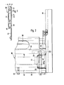
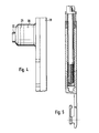
- connection points of the side supports with the shaft rods of a heald frame designed according to the invention are explained in more detail with reference to the attached drawing.
- the one side wall 12 is extended beyond a lower narrow side 16 of the shaft rod 10 to a holding part 17 which, according to FIGS. 2 and 3, can have larger cutouts 36.
- shaft rods 10 form the upper and lower frame legs of the heald frame in a known manner and are also advantageously provided with profiled but narrower side supports 18 connected to each other.
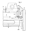
- FIG. 2 shows the lower right corner and FIG. 3 the upper right corner of a heald frame, where a side support 18 is in each case connected to a shaft rod 10.
- the side support 18 is provided at both ends with a solid web-like lateral projection 19 and 20, which has the same thickness B as the shaft rod 10.
- Both projections 19 and 20 also have an extension 21 and 22, which has a smaller thickness, which corresponds to the inside width of the cavity 14 of the shaft rods 10.
- both the lower shaft rod 10 visible from FIG. 2, and the upper shaft shaft 10, shown in FIG.
- the heald frame are provided with an end-side recess 23 and 24 which, except for the corners, conforms exactly to the shape the projections 19, 20 are adapted so that the projections 19 and 20 can be inserted without tilting into the recesses 23, 24 of the shaft rods 10 formed by milling, the extensions 21 and 22 being immersed in the adjoining cavity 14 of the shaft rods 10.
- the projections 19 and 20 are thus supported almost over their entire circumference at the edges of the cutouts 23 and 24 and thus on the side walls 11 and 12 of the shaft rods 10.
- the projection 20 (and in the same way also the lower projection 19 of the shaft rod 18) is provided with a through hole 25.
- the through hole 25 serves to pass an anchoring screw 26 or 27.
- the other end provided with a thread 27.2 of the anchoring screw 27 is screwed into a threaded bore of a second jaw 29, which is inserted into the cavity 15 of the shaft rod 10 and held there by means of a dowel pin 30, which is held by a transverse bore in the jaw 29 and with it aligned holes in the side walls 11 and 12 of the shaft rod 10 protrudes.
- the anchoring screw 26 serves at the same time for fastening a shaft drive piece 31 placed on the upper narrow side 13 of the shaft rod, on which the shaft drive device acts, but whose known structure is of no further interest.
- the base 31.1 of this shaft drive piece 31 here forms the jaws, against which the head 26.1 of the anchoring screw 26 rests, the threaded other end 26.2 of which can be screwed into the threaded bore of a second jaw 32 which is inserted into the cavity 15 of the shaft rod. While the jaw 28 shown in FIG.
- the side supports 18 can be easily and quickly released from the shaft rods 10.
- the jaws 29 and 32 serving to anchor the clamping screws 26 and 27 with their threaded bores are expediently made of steel. Anchoring of the screws in the relatively soft aluminum material of the shaft ends 10 is thus avoided.
- the jaws can be easily replaced if the threads of their holes are damaged.
Landscapes
- Engineering & Computer Science (AREA)
- Textile Engineering (AREA)
- Looms (AREA)
- Mutual Connection Of Rods And Tubes (AREA)
- Woven Fabrics (AREA)
- Tents Or Canopies (AREA)
- Joining Of Building Structures In Genera (AREA)
- Shafts, Cranks, Connecting Bars, And Related Bearings (AREA)
- Forging (AREA)
- Superconductors And Manufacturing Methods Therefor (AREA)
- Heat Treatment Of Articles (AREA)
Priority Applications (1)
| Application Number | Priority Date | Filing Date | Title |
|---|---|---|---|
| AT87104061T ATE54684T1 (de) | 1986-03-25 | 1987-03-19 | Webeschaft mit schaftstaeben aus einem aluminiumprofil. |
Applications Claiming Priority (2)
| Application Number | Priority Date | Filing Date | Title |
|---|---|---|---|
| DE19863609964 DE3609964A1 (de) | 1986-03-25 | 1986-03-25 | Webeschaft mit schaftstaeben aus einem aluminiumprofil |
| DE3609964 | 1986-03-25 |
Publications (3)
| Publication Number | Publication Date |
|---|---|
| EP0239013A2 EP0239013A2 (de) | 1987-09-30 |
| EP0239013A3 EP0239013A3 (en) | 1988-02-17 |
| EP0239013B1 true EP0239013B1 (de) | 1990-07-18 |
Family
ID=6297187
Family Applications (1)
| Application Number | Title | Priority Date | Filing Date |
|---|---|---|---|
| EP87104061A Expired - Lifetime EP0239013B1 (de) | 1986-03-25 | 1987-03-19 | Webeschaft mit Schaftstäben aus einem Aluminiumprofil |
Country Status (6)
| Country | Link |
|---|---|
| US (1) | US4753273A (cs) |
| EP (1) | EP0239013B1 (cs) |
| JP (1) | JPS62243845A (cs) |
| AT (1) | ATE54684T1 (cs) |
| CS (1) | CS274613B2 (cs) |
| DE (2) | DE3609964A1 (cs) |
Families Citing this family (9)
| Publication number | Priority date | Publication date | Assignee | Title |
|---|---|---|---|---|
| DE4001264A1 (de) * | 1990-01-18 | 1991-07-25 | Egelhaaf C C Maschf | Mittelverbinder fuer insbesondere metallische webeschaefte |
| US5056231A (en) * | 1990-06-01 | 1991-10-15 | Bear Automotive Service Equipment Co. | Apparatus for locking wheel unit in automotive wheel alignment system |
| US6076250A (en) * | 1996-01-13 | 2000-06-20 | Firma Schmeing Gmbh & Co. | Process for producing a heald shaft for weaving shafts out of a metal hollow section |
| DE19612404A1 (de) * | 1996-03-28 | 1997-10-02 | Grob & Co Ag | Eckverbindung für einen Webschaft |
| DE19858013C2 (de) * | 1998-12-01 | 2001-02-01 | Schmeing Gmbh & Co | Verbindung zwischen Schaftstab und Seitenstütze bei Webschäften mit reiterlosem Schaft-Litzensystem |
| DE10325908B4 (de) * | 2003-06-05 | 2005-07-21 | Groz-Beckert Kg | Schaftstab, Webschaft und Verfahren zur Herstellung eines Schaftstabs |
| FR2857987B1 (fr) * | 2003-07-21 | 2005-10-07 | Staubli Sa Ets | Cadre de lisses et metier a tisser equipe d'au moins un tel cadre |
| EP2037020B1 (de) * | 2007-09-12 | 2015-11-04 | Groz-Beckert KG | Profilstab und Tragstab für einen Webschaft |
| EP3241932B1 (de) * | 2016-05-02 | 2019-11-20 | Groz-Beckert KG | Webschaft und herstellverfahren für einen webschaft |
Family Cites Families (8)
| Publication number | Priority date | Publication date | Assignee | Title |
|---|---|---|---|---|
| AT261503B (de) * | 1965-04-30 | 1968-04-25 | Grob & Co Ag | Webschaft mit einer lösbaren Eckverbindung |
| CH427688A (de) * | 1965-04-30 | 1966-12-31 | Grob & Co Ag | Webschaft mit einer lösbaren Eckverbindung |
| CH538560A (de) * | 1971-05-13 | 1973-06-30 | Grob & Co Ag | Webschaft |
| DE2126074A1 (de) * | 1971-05-26 | 1972-12-07 | Fa. CC. Egelhaaf, 7411 Reutlingen-Betzingen | Litzentragschienenhalter-Verriegelung für Webeschäfte |
| US3949789A (en) * | 1972-06-14 | 1976-04-13 | Grob & Co. Aktiengesellschaft | Heddle frame stave with closed T-rail |
| AT315767B (de) * | 1972-06-28 | 1974-06-10 | Grob & Co Ag | Hohler Schaftstab |
| JPS5514185A (en) * | 1978-07-18 | 1980-01-31 | Sintokogio Ltd | Solvent of facing material for reduced-pressure-molded casting mold |
| DE3017629A1 (de) * | 1980-05-08 | 1981-11-12 | Kabushiki Kaisha Maruyama Seisakusho, Sakai | Webschaft |
-
1986
- 1986-03-25 DE DE19863609964 patent/DE3609964A1/de not_active Withdrawn
-
1987
- 1987-03-19 DE DE8787104061T patent/DE3763713D1/de not_active Expired - Fee Related
- 1987-03-19 EP EP87104061A patent/EP0239013B1/de not_active Expired - Lifetime
- 1987-03-19 AT AT87104061T patent/ATE54684T1/de active
- 1987-03-24 US US07/030,067 patent/US4753273A/en not_active Expired - Fee Related
- 1987-03-24 JP JP62068176A patent/JPS62243845A/ja active Pending
- 1987-03-24 CS CS198287A patent/CS274613B2/cs unknown
Also Published As
| Publication number | Publication date |
|---|---|
| DE3609964A1 (de) | 1987-10-01 |
| DE3763713D1 (de) | 1990-08-23 |
| US4753273A (en) | 1988-06-28 |
| EP0239013A3 (en) | 1988-02-17 |
| CS274613B2 (en) | 1991-09-15 |
| JPS62243845A (ja) | 1987-10-24 |
| ATE54684T1 (de) | 1990-08-15 |
| EP0239013A2 (de) | 1987-09-30 |
| CS198287A2 (en) | 1990-11-14 |
Similar Documents
| Publication | Publication Date | Title |
|---|---|---|
| DE1535854C2 (de) | Webschaft mit einer losbaren Eckver bindung | |
| AT405757B (de) | Verbindungsstück für die lösbare verbindung zweier profilstäbe, vorzugsweise aus leichtmetall | |
| EP0136431A2 (de) | Konstruktion aus Profilstäben | |
| DE29506820U1 (de) | Barre mit Modulen für Tuftingwerkzeuge (I) | |
| EP0050242A2 (de) | Verbindung für Rahmenteile von Möbeln, insbesondere Büromöbeln | |
| DE4139185A1 (de) | Hohler profilstab, insbesondere aus leichtmetall | |
| EP0539687B1 (de) | Querverbindung für Profilstäbe mit hinterschnittenen Längsnuten | |
| EP0239013A2 (de) | Webeschaft mit Schaftstäben aus einem Aluminiumprofil | |
| DE2218066B2 (de) | Webschaft | |
| EP0541918A1 (de) | Querverbindung von Profilstäben | |
| DE10116813B4 (de) | Webschafteckverbindung | |
| EP0616135B1 (de) | Verbindungseinrichtung für Profilteile | |
| WO2004097090A1 (de) | Webschaft für eine webmaschine | |
| DE9012607U1 (de) | Klemmelement für eine Klemmvorrichtung | |
| EP0423474B1 (de) | Vorrichtung zum lösbaren Verbinden von zwei Profilstäben | |
| DE3401468C2 (de) | Tragvorrichtung für elektrische Einrichtungen | |
| DE4124157C2 (de) | Modulplatte, Träger o. dgl. Element zur Verwendung bei Maschinenaufbauten | |
| DE4027935C2 (de) | Klemmvorrichtung oder Klemmverbund | |
| EP0130145B1 (de) | Lösbare Verbindung für Holzbalken | |
| DE1954810C3 (de) | Beschlag zum lösbaren Verbinden zweier senkrecht aufeinanderstoßender plattenförmiger Bauteile, insbesondere Möbelteile | |
| DE8608183U1 (de) | Webeschaft mit Schaftstäben aus einem Aluminiumprofil | |
| CH719422B1 (de) | Verbindungseinrichtung für Tragelemente für ein Traggerüst sowie ein Traggerüst für Personen- und/oder Warenaufzüge | |
| DE8704548U1 (de) | Querverbinder für Profilstäbe | |
| DE2552983C3 (de) | Von außen herstellbare Verbindung zweier Wand an Wand benachbarter Gehäuse | |
| EP0876788A2 (de) | Mit einem Wandhalter versehenes, im Querschnitt U-förmiges Halteprofil für eine Trennwand |
Legal Events
| Date | Code | Title | Description |
|---|---|---|---|
| PUAI | Public reference made under article 153(3) epc to a published international application that has entered the european phase |
Free format text: ORIGINAL CODE: 0009012 |
|
| AK | Designated contracting states |
Kind code of ref document: A2 Designated state(s): AT BE CH DE FR GB IT LI NL |
|
| PUAL | Search report despatched |
Free format text: ORIGINAL CODE: 0009013 |
|
| AK | Designated contracting states |
Kind code of ref document: A3 Designated state(s): AT BE CH DE FR GB IT LI NL |
|
| 17P | Request for examination filed |
Effective date: 19880323 |
|
| 17Q | First examination report despatched |
Effective date: 19890830 |
|
| GRAA | (expected) grant |
Free format text: ORIGINAL CODE: 0009210 |
|
| AK | Designated contracting states |
Kind code of ref document: B1 Designated state(s): AT BE CH DE FR GB IT LI NL |
|
| REF | Corresponds to: |
Ref document number: 54684 Country of ref document: AT Date of ref document: 19900815 Kind code of ref document: T |
|
| REF | Corresponds to: |
Ref document number: 3763713 Country of ref document: DE Date of ref document: 19900823 |
|
| ET | Fr: translation filed | ||
| ITF | It: translation for a ep patent filed | ||
| GBT | Gb: translation of ep patent filed (gb section 77(6)(a)/1977) | ||
| PGFP | Annual fee paid to national office [announced via postgrant information from national office to epo] |
Ref country code: BE Payment date: 19910221 Year of fee payment: 5 |
|
| PGFP | Annual fee paid to national office [announced via postgrant information from national office to epo] |
Ref country code: FR Payment date: 19910222 Year of fee payment: 5 |
|
| PGFP | Annual fee paid to national office [announced via postgrant information from national office to epo] |
Ref country code: CH Payment date: 19910225 Year of fee payment: 5 |
|
| PGFP | Annual fee paid to national office [announced via postgrant information from national office to epo] |
Ref country code: GB Payment date: 19910308 Year of fee payment: 5 |
|
| PGFP | Annual fee paid to national office [announced via postgrant information from national office to epo] |
Ref country code: AT Payment date: 19910326 Year of fee payment: 5 |
|
| PGFP | Annual fee paid to national office [announced via postgrant information from national office to epo] |
Ref country code: DE Payment date: 19910327 Year of fee payment: 5 |
|
| ITTA | It: last paid annual fee | ||
| PGFP | Annual fee paid to national office [announced via postgrant information from national office to epo] |
Ref country code: NL Payment date: 19910331 Year of fee payment: 5 |
|
| PLBE | No opposition filed within time limit |
Free format text: ORIGINAL CODE: 0009261 |
|
| STAA | Information on the status of an ep patent application or granted ep patent |
Free format text: STATUS: NO OPPOSITION FILED WITHIN TIME LIMIT |
|
| 26N | No opposition filed | ||
| PG25 | Lapsed in a contracting state [announced via postgrant information from national office to epo] |
Ref country code: GB Effective date: 19920319 Ref country code: AT Effective date: 19920319 |
|
| PG25 | Lapsed in a contracting state [announced via postgrant information from national office to epo] |
Ref country code: LI Effective date: 19920331 Ref country code: CH Effective date: 19920331 Ref country code: BE Effective date: 19920331 |
|
| BERE | Be: lapsed |
Owner name: C.C. EGELHAAF G.M.B.H. & CO. MASCHINENFABRIK K.G. Effective date: 19920331 |
|
| PG25 | Lapsed in a contracting state [announced via postgrant information from national office to epo] |
Ref country code: NL Effective date: 19921001 |
|
| NLV4 | Nl: lapsed or anulled due to non-payment of the annual fee | ||
| GBPC | Gb: european patent ceased through non-payment of renewal fee | ||
| PG25 | Lapsed in a contracting state [announced via postgrant information from national office to epo] |
Ref country code: FR Effective date: 19921130 |
|
| REG | Reference to a national code |
Ref country code: CH Ref legal event code: PL |
|
| PG25 | Lapsed in a contracting state [announced via postgrant information from national office to epo] |
Ref country code: DE Effective date: 19921201 |
|
| REG | Reference to a national code |
Ref country code: FR Ref legal event code: ST |
|
| PG25 | Lapsed in a contracting state [announced via postgrant information from national office to epo] |
Ref country code: IT Free format text: LAPSE BECAUSE OF NON-PAYMENT OF DUE FEES Effective date: 20050319 |