EP0237984A2 - Verfahren zur Emissionsanalyse mit induktionsgekoppeltem Radiofrequenzplasma und Vorrichtung zu diesem Verfahren - Google Patents
Verfahren zur Emissionsanalyse mit induktionsgekoppeltem Radiofrequenzplasma und Vorrichtung zu diesem Verfahren Download PDFInfo
- Publication number
- EP0237984A2 EP0237984A2 EP87103687A EP87103687A EP0237984A2 EP 0237984 A2 EP0237984 A2 EP 0237984A2 EP 87103687 A EP87103687 A EP 87103687A EP 87103687 A EP87103687 A EP 87103687A EP 0237984 A2 EP0237984 A2 EP 0237984A2
- Authority
- EP
- European Patent Office
- Prior art keywords
- plasma
- plasma torch
- sample
- radio frequency
- analyzing
- Prior art date
- Legal status (The legal status is an assumption and is not a legal conclusion. Google has not performed a legal analysis and makes no representation as to the accuracy of the status listed.)
- Granted
Links
Images

Classifications
-
- G—PHYSICS
- G01—MEASURING; TESTING
- G01N—INVESTIGATING OR ANALYSING MATERIALS BY DETERMINING THEIR CHEMICAL OR PHYSICAL PROPERTIES
- G01N21/00—Investigating or analysing materials by the use of optical means, i.e. using sub-millimetre waves, infrared, visible or ultraviolet light
- G01N21/62—Systems in which the material investigated is excited whereby it emits light or causes a change in wavelength of the incident light
- G01N21/71—Systems in which the material investigated is excited whereby it emits light or causes a change in wavelength of the incident light thermally excited
- G01N21/73—Systems in which the material investigated is excited whereby it emits light or causes a change in wavelength of the incident light thermally excited using plasma burners or torches
Definitions
- the present invention relates to an emission analysis method with an inductively-coupled radio frequency plasma as a source for emission analysis and an appa - ratus for use in such method and, more particulary, to an emission analysis method with an inductively-coupled radio frequency plasma as a source for emission analysis and an apparatus for use in such method.
- Emission analysis in the present context means that a sample is exposed to electrical or thermal energy, whereby, the spectra of emitted light are analysed by a spectroscope to obtain the spectra peculiar to elements contained in the sample. The presence and the strength of the spectra are measured to perform quantitative or qualitative analysis of the elements.
- an inductively-coupled radio frequency plasma (referred as to ICP hereinafter) is suitable for performing the quantitative or qualitative analysis of a soldered sample as a source.
- the ICP As a high frequency plasma for a source, the ICP is characterized in that a high frequency current less than 300MHz flows through a coil to cause a high frequency magnetic field. According to the change of the high frequency magnetic field, an electromagnetic induction field is caused to discharge, whereby the combination of the discharge and an electric circuit becomes inductive.
- a light source of this type is called ICP.
- the ICP system can afford stable plasma and high precision of analysis.
- a sample inlet system should be stabilized for each of the samples. Therefore, a gas inlet system to a plasma torch and a high frequency voltage source for generating a high frequency magnetic field are continuously operated in an appropriate analysis condition even without analysis. It takes about 10-20 sec. to introduce a new sample into a plasma torch and analyze it.
- the time necessary for stabilizing a plasma and the sample inlet.system is extemely long, so that the necessary volume of argon gas to be introduced into the plasma torch and consumed therein is great, up.to about 10-20 l/min and the power consumption is also great, i.e. up to 10-2 kw/h. Since argon gas is expensive, the running cost become extremely high.
- an object of the present invention to provide an improved emission analysis method with an Inductively-Coupled Radio Frequency Plasma (ICP) and an apparatus for use in such a method aiming to reduce the running cost of the IPC analysis.
- ICP Inductively-Coupled Radio Frequency Plasma
- an analyzing method of an Inductively-Coupled Radio Frequency Plasma comprising a switch valve for switching the flow of a sample, the switch valve being interposed between a sample nebulizing chamber and a plasma torch, comprising the steps of: switching the switch valve to the side of the plasma torch only during an ICP analyzing time to introduce the sample into the plasma torch; supplying an induction coil with a first radio frequency electric power and the plasma torch of a first volume of gas in such a condition that the sample introduced into the plasma torch is ionized as plasma; analyzing the plasma of the sample; switching the switch valve to an exit side of the sample during times excect for the ICP analyzing time; and supplying the induction coil with a second radio frequency electric power and the plasma torch of a second volume of gas in such a condition that a pilot light plasma is maintained in the plasma torch; and an appratus for analyzing a sample using Inductively-Coupled Radio Frequency Plasma including a plasma
- ICP Inductively-Coupled Radio Frequency Plasma
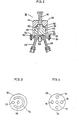
- a plasma torch 2 comprises an external tube 4, first and second inner tubes 8 which are coaxially aligned within the inner portion of the external tube 4.
- An induction coil 10 is wound-around the top portion of the plasma torch 2 in order to generate a radio frequency magnetic field.
- a coolant gas (e.g. Argon gas) inlet tube 12 is provided at an opening formed at the lower portion of the external tube 4.
- a plasma gas (e.g. Argon gas) inlet tube 14 is connected.
- the lower end of the second inner tube 8 is extending through an opening of the external tube 4, and the extending end of the second inner tube 8 is connected to an exit port 18 of a switch valve 16.
- the induction coil 10 is coupled to a radio frequency voltage source 22 via an impedance matching unit 20.
- the radio frequency voltage source 22 supplies the induction coil 10 with radio frequency power, so that the induction coil generates a radio frequency magnetic field around the plasma torch 2.
- the coolant gas inlet tube 12 and the plasma gas inlet tube 14 are connected to a gas supply control unit 24.
- the switch valve 16 is provided with the exit port 18 and two inlet ports, one of which is an exit port 26' and the remaining is an inlet port 26 for a mixture gas of solution samples and a carrier gas.
- the switch valve 16 comprises a rotation member rotated by a pulse motor 28, so that the inlet port 26 for the mixture gas and the exit port 26' are connected together during a waiting condition time except for an analyzing time while the inlet port 26 for the mixture gas and the exit port 18 are connected together during the analyzing time.
- the pulse motor 28 drives the rotation member of the switch valve 16.
- the ICP system comprises a solution sample container 32, a sample nebu-lizering chamber 34, a solution sample absorbing tube 35, a carrier gas (e.g. Argon gas) inlet tube 36, and a nebulizer 38.
- the carrier gas inlet tube 36 is connected to the gas supply controller 24.
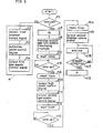
- a central processing unit (CPU) circuit 40 comprises a micro-computer including a CPU 40a, a read only memory (ROM) 40b storing an operation program as shown in the flow chart of FIG. 5, and a random access memory (RAM) 40c storing data for access, an input port 40d for inputting an operation signal from an operation unit 42 to the CPU 40a, and an output port 40e for outputting the signal from the CPU 40a into the radio frequency power source 22, the gas supply controller 24, and the chamber controller 30.
- CPU central processing unit
- ROM read only memory
- RAM random access memory
- the CPU circuit 40 provides a low power driving signal to the radio frequency power source 22 during a waiting condition time except for an analyzing time while it provides a high power driving signal to the power source 22 during the analyzing time.
- the CPU circuit 40 provides the gas supply controller 24 with a gas supply amount control signal.
- the gas supply controller 24 comprises a processing circuit responsive to the gas supply amount control signal and a valve driving section responsive to the processing circuit for switching on an off valves for the inlet tubes 12, 14 and 36.
- the gas supply controller 24 is connected to a gas cylinder supplying the coolant gas, the plasma gas, and the carrier gas, via a gas supply tube 27.
- the CPU circuit 40 provides the chamber controller 30 with a chamber control signal, so that responsive to the chamber control signal, the chamber controller 30 provides the pulse motor 28 with a pulse motor driving signal.
- FIG. 2 is a cross-section view of the switch valve 16 which comprises a cylindrical casing 44.
- the exit port 18 to which the first inner tube 8 in the plasma torch 2 is connected is screwed into the topwall 46.
- a flange 50 is formed at the circumference of the lower side of a side wall 48 of the casing 44.
- a lid 54 is secured on the casing 44 through a pair of bolts 52 penetrating the flange 50.
- the rotation axis 56 of the pulse motor 28 is inserted into the lid 54 to form four inlet ports 26.
- a rotation member is arranged which is connected to the rotation axis 56 and rotated by the pulse motor 28.
- a path 60 is provided passing through the rotation member 58.
- the top end of the path 60 is connected to the exit port 18 while the bottom end is connected to the inlet port 26.
- a seal material 62 is provided between the inner circumferential edge of the lid 54 and the casing 44.
- FIG. 3 is a plan view of a slide surface 64 on which the rotation member 58 is slided as opposed to the lid 54.
- FIG. 4 is a plan view of a surface 66 opposed to the slide surface 64, viewed from the side of the lid 54.
- the slide surface 62 of the rotation member 58 includes a hole 68 at the center in which the rotation axis 56 of the pulse motor 28 is inserted.
- a bottom end 70 of the path 60 is positioned while along the same circle a circle groove 72 is formed over approximately three-fourth of the circle.
- an opening 74 is provided at the center of the surface 66 opposed to the lid 54.
- the rotation axis 56 of the pulse motor 28 is inserted into the opening 74.
- four openings 76 are provided at approximately right angle to each other for connecting the four inlet ports 26.
- the CPU 40a of the CPU circuit 40 determined whether the operation unit 42 inputs a signal for ICP analyzing instruction (step n1). When it is detected that no such instruction signal is provided (NO) and that a waiting condition exists, a first chamber control signal is outputted into the chamber controller 30 via the output port 40e (step n2). Responsive to the first chamber control signal, the chamber controller 30 outputs a driving signal to the pulse motor 28, so that the inlet port 26 and the exit port 26' of the lid 54 are connected through the circle groove 72 of the rotation member 58 by driving the pulse motor 28. The pulse motor 28 is therefore driven to rotate the rotation member 58 engaged with the rotation axis 56 of the pulse motor 28. Thus, the inlet port 26 and the exit port 26' of the lid 54 are coupled to each other through the circle groove 72.
- the CPU 40a of the CPU circuit40 provides a low electric power control signal to the radio frequency voltage source 22 (step n3).
- the radio frequency voltage source 22 provides low power, related to the low electric power control signal, to the induction coil 10 via the impedance matching unit 20.
- the low electric power is about 100 W/h.
- the CPU 40a provides a first gas supply control signal to the gas supply controller 24, so that the total gas to be supplied to the plasma torch 2 should be a predetermined amount, for example, about 1.5 l/min by controlling the opening of an inner valve (step n4). Responsive to the first gas supply control signal, the gas supply controller 24 controls the inner valve so as to limit the total amount of gas supplied by the gas cylinder 25 into the predetermined amount.
- steps n2 - n4 (collectively referred to as a common step M), the waiting condition except for the ICP analyzing period is placed in which the plasma torch 2 is in the condition of a pilot light to thereby reduce consumption of power from the radio frequency voltage source 22.
- step n5 the program is advanced to step n5.
- the operation of step n5 is identical with that of step M.
- step n5 the plasma torch 2 is.maintained in the condition of the pilot light and the switch valve 16 is in the condition of expelling the sample.
- step M to stabilize the sample entry system comprising the nebulizer 38 and the sample nebulizing chamber 34, the CPU 40a provides a signal enabling the solution sample and the carrier gas to be mixed in the nebulizer-38 and the mixture gas to be nebulized within the sample nebulizing chamber 34 (step n6). Then, a timer starts to count about 2 - 3 minutes during which the nebulizing condition is continued (steps n7 and n8). When the time counting is up, step n9 is selected to reset the timer.
- the CPU 40a provides a high electric power control signal into the radio frequency voltage source 22 via the output port 40e, so that the power from the radio frequency voltage source 22 subsequently increases up to about 1.2 k W/ h, for example (step n10), and simultaneously provides a second gas supply control signal to the gas supply controller 24 (step n11).
- the gas supply controller 24 controls the increasing opening of the inner valve, so that the total gas supplied into the plasma torch 2 reaches a predetermined volume, for example, about 15 l/min (step n11).
- Step n12 is then selected to start a timer counting the time when with these steps the radio frequency voltage source 22 can output high power of about 1.2 kW/h and the gas supply controller 24 can output the volume of gas about 15 l/min. That is, the timer counts before the sample entry system can be stabilized.
- Step n13 is operated-to detect that the time counting is up, and step n14 is operated to reset the timer.
- the CPU 40a outputs a second chamber control signal into the chamber controller 30 (step n15). Responsive to the second chamber control signal, the chamber controller 30 drives the pulse motor 28, so that the pulse motor 28 rotates the rotation member 58 in the switch valve 16. The inlet port 26 of the switch valve 16, the path 60, and the outlet port 18 are then connected, so that the sample within the sample nebulizing chamber 34 is introduced into the plasma torch 2. The introduced sample is ionized in the plasma torch 2.
- Step n16 is selected to analyze the sample.
- Step n17 is selected to determine whether analysis has been completed.
- step n18 is selected to perform the operation similar to that of step M.
- the plasma torch 2 in the remaining conditions except for analysis the plasma torch 2 is kept in condition of the pilot light, so that the gas entry volume and electric power to be supplied to and consumed in the plasma torch 2 can be reduced to one tenth or less as compared to the conventional case.
- the running cost of the ICP analysis can be reduced considerably.
- the impedance of the load in the radio frequency voltage source 22 should be matched with that of the plasma torch 2 to eliminate reflection loss and to keep the precision of-analysis. According to the present invention, it takes about 10-20 sec to enable the plasma torch 2 to analyze the sample. Without impedance matching and with generating reflection wave, the ICP analysis may be possible to simplify analysis operation.
Landscapes
- Health & Medical Sciences (AREA)
- Physics & Mathematics (AREA)
- Chemical & Material Sciences (AREA)
- Plasma & Fusion (AREA)
- Nuclear Medicine, Radiotherapy & Molecular Imaging (AREA)
- Life Sciences & Earth Sciences (AREA)
- Engineering & Computer Science (AREA)
- Analytical Chemistry (AREA)
- Biochemistry (AREA)
- General Health & Medical Sciences (AREA)
- General Physics & Mathematics (AREA)
- Immunology (AREA)
- Pathology (AREA)
- Investigating, Analyzing Materials By Fluorescence Or Luminescence (AREA)
- Other Investigation Or Analysis Of Materials By Electrical Means (AREA)
Applications Claiming Priority (2)
| Application Number | Priority Date | Filing Date | Title |
|---|---|---|---|
| JP61555/86 | 1986-03-18 | ||
| JP61061555A JPH0640074B2 (ja) | 1986-03-18 | 1986-03-18 | Icp分析方法 |
Publications (3)
| Publication Number | Publication Date |
|---|---|
| EP0237984A2 true EP0237984A2 (de) | 1987-09-23 |
| EP0237984A3 EP0237984A3 (en) | 1990-01-10 |
| EP0237984B1 EP0237984B1 (de) | 1993-06-02 |
Family
ID=13174474
Family Applications (1)
| Application Number | Title | Priority Date | Filing Date |
|---|---|---|---|
| EP87103687A Expired - Lifetime EP0237984B1 (de) | 1986-03-18 | 1987-03-13 | Verfahren zur Emissionsanalyse mit induktionsgekoppeltem Radiofrequenzplasma und Vorrichtung zu diesem Verfahren |
Country Status (5)
| Country | Link |
|---|---|
| US (1) | US4906582A (de) |
| EP (1) | EP0237984B1 (de) |
| JP (1) | JPH0640074B2 (de) |
| CN (1) | CN1013410B (de) |
| DE (1) | DE3786027T2 (de) |
Families Citing this family (10)
| Publication number | Priority date | Publication date | Assignee | Title |
|---|---|---|---|---|
| JPH02253139A (ja) * | 1989-03-28 | 1990-10-11 | Seiko Instr Inc | 高周波誘導結合プラズマ発光分光分析装置用試料導入方法 |
| US5280154A (en) * | 1992-01-30 | 1994-01-18 | International Business Machines Corporation | Radio frequency induction plasma processing system utilizing a uniform field coil |
| JPH10241625A (ja) * | 1997-02-24 | 1998-09-11 | Hitachi Ltd | プラズマイオン源質量分析装置及び方法 |
| US6222186B1 (en) | 1998-06-25 | 2001-04-24 | Agilent Technologies, Inc. | Power-modulated inductively coupled plasma spectrometry |
| US6121570A (en) | 1998-10-28 | 2000-09-19 | The Esab Group, Inc. | Apparatus and method for supplying fluids to a plasma arc torch |
| DE19932630C2 (de) | 1999-07-13 | 2003-12-04 | Perkin Elmer Bodenseewerk Zwei | Einheit für eine Plasma-Atomisierungsvorrichtung mit Plasma-Gaszuführeinrichtung, Probenzerstäubereinrichtung und Probeninjektionseinrichtung |
| DE102004046814B3 (de) * | 2004-09-27 | 2006-03-09 | Siemens Ag | Verfahren und Vorrichtung zur Beeinflussung von Verbrennungsvorgängen, insbesondere zum Betrieb einer Gasturbine |
| JP5148367B2 (ja) * | 2007-05-29 | 2013-02-20 | 信越化学工業株式会社 | 高周波誘導熱プラズマトーチを用いた光ファイバプリフォームの製造方法 |
| CN102507536A (zh) * | 2011-11-16 | 2012-06-20 | 天津重型装备工程研究有限公司 | 分析可通过氢化反应生成氢化物气体的痕量元素的方法 |
| JP6048068B2 (ja) * | 2012-10-25 | 2016-12-21 | 株式会社島津製作所 | プラズマ用高周波電源及びそれを用いたicp発光分光分析装置 |
Family Cites Families (4)
| Publication number | Priority date | Publication date | Assignee | Title |
|---|---|---|---|---|
| US3809850A (en) * | 1972-05-17 | 1974-05-07 | Union Carbide Corp | Plasma arc power system for welding |
| US4578022A (en) * | 1983-08-12 | 1986-03-25 | Kenney George B | Apparatus for in-process multi-element analysis of molten metal and other liquid materials |
| US4575609A (en) * | 1984-03-06 | 1986-03-11 | The United States Of America As Represented By The United States Department Of Energy | Concentric micro-nebulizer for direct sample insertion |
| US4689754A (en) * | 1985-02-21 | 1987-08-25 | The Perkin-Elmer Corporation | Optimization apparatus and procedure |
-
1986
- 1986-03-18 JP JP61061555A patent/JPH0640074B2/ja not_active Expired - Fee Related
-
1987
- 1987-03-10 CN CN87101801A patent/CN1013410B/zh not_active Expired
- 1987-03-13 DE DE87103687T patent/DE3786027T2/de not_active Expired - Fee Related
- 1987-03-13 EP EP87103687A patent/EP0237984B1/de not_active Expired - Lifetime
-
1988
- 1988-10-06 US US07/256,404 patent/US4906582A/en not_active Expired - Lifetime
Also Published As
| Publication number | Publication date |
|---|---|
| CN87101801A (zh) | 1987-10-07 |
| DE3786027T2 (de) | 1994-01-20 |
| EP0237984A3 (en) | 1990-01-10 |
| CN1013410B (zh) | 1991-07-31 |
| DE3786027D1 (de) | 1993-07-08 |
| EP0237984B1 (de) | 1993-06-02 |
| JPH0640074B2 (ja) | 1994-05-25 |
| US4906582A (en) | 1990-03-06 |
| JPS62215851A (ja) | 1987-09-22 |
Similar Documents
| Publication | Publication Date | Title |
|---|---|---|
| EP0237984B1 (de) | Verfahren zur Emissionsanalyse mit induktionsgekoppeltem Radiofrequenzplasma und Vorrichtung zu diesem Verfahren | |
| US5095247A (en) | Plasma discharge apparatus with temperature sensing | |
| US6242735B1 (en) | Power-modulated inductively coupled plasma spectrometry | |
| US5086255A (en) | Microwave induced plasma source | |
| Barnes et al. | Recent advances in emission spectroscopy: Inductively coupled plasma discharges for spectrochemical analysis | |
| US20080035844A1 (en) | Inductively coupled plasma mass spectrometer | |
| EP0792091A1 (de) | Verfahren und Vorrichtung zur elementaren Analyse | |
| JP2001523570A (ja) | 汚染低減のためのモジュラー型誘電バリア放電装置 | |
| JP2014055785A (ja) | プラズマ用高周波電源及びそれを用いたicp発光分光分析装置 | |
| CA3208773A1 (en) | Inductively coupled plasma torches and methods and systems including same | |
| Blades et al. | Application of weakly ionized plasmas for materials sampling and analysis | |
| US7746451B1 (en) | On-chip microplasma systems | |
| EP3654739A1 (de) | Plasmaerzeugungsvorrichtung, lichtemissionsanalysevorrichtung und massenanalysevorrichtung mit der plasmaerzeugungsvorrichtung und vorrichtungsstatusauswertungsverfahren | |
| Timmermans et al. | The influence of molecular gases and analytes on excitation mechanisms in atmospheric microwave sustained argon plasmas | |
| US5130537A (en) | Plasma analyzer for trace element analysis | |
| Seeböck et al. | Temporal intensity modulation of spectral lines in a low‐frequency discharge in argon | |
| JP2008202990A (ja) | Icp用高周波電源装置 | |
| JPH0615392Y2 (ja) | 高周波誘導結合プラズマ質量分析計 | |
| US5763877A (en) | Analyzer using plasma and analysis method using plasma, interface used for the same and sample introducing component used for the same | |
| JP2656259B2 (ja) | イオン発生装置 | |
| JP2000057990A (ja) | 質量分析計 | |
| JPH07118298B2 (ja) | 高周波誘導結合プラズマ質量分析計 | |
| RU2779718C1 (ru) | Способ определения элементного состава капельных жидкостей | |
| JPS6165154A (ja) | 金属試料中の炭素,硫黄成分の迅速分析方法および装置 | |
| JPH0582289A (ja) | マイクロ波プラズマ処理方法および装置 |
Legal Events
| Date | Code | Title | Description |
|---|---|---|---|
| PUAI | Public reference made under article 153(3) epc to a published international application that has entered the european phase |
Free format text: ORIGINAL CODE: 0009012 |
|
| AK | Designated contracting states |
Kind code of ref document: A2 Designated state(s): DE FR GB |
|
| PUAL | Search report despatched |
Free format text: ORIGINAL CODE: 0009013 |
|
| AK | Designated contracting states |
Kind code of ref document: A3 Designated state(s): DE FR GB |
|
| 17P | Request for examination filed |
Effective date: 19900125 |
|
| 17Q | First examination report despatched |
Effective date: 19921002 |
|
| GRAA | (expected) grant |
Free format text: ORIGINAL CODE: 0009210 |
|
| AK | Designated contracting states |
Kind code of ref document: B1 Designated state(s): DE FR GB |
|
| REF | Corresponds to: |
Ref document number: 3786027 Country of ref document: DE Date of ref document: 19930708 |
|
| ET | Fr: translation filed | ||
| PLBE | No opposition filed within time limit |
Free format text: ORIGINAL CODE: 0009261 |
|
| STAA | Information on the status of an ep patent application or granted ep patent |
Free format text: STATUS: NO OPPOSITION FILED WITHIN TIME LIMIT |
|
| 26N | No opposition filed | ||
| PGFP | Annual fee paid to national office [announced via postgrant information from national office to epo] |
Ref country code: GB Payment date: 19980304 Year of fee payment: 12 |
|
| PGFP | Annual fee paid to national office [announced via postgrant information from national office to epo] |
Ref country code: FR Payment date: 19980310 Year of fee payment: 12 |
|
| PGFP | Annual fee paid to national office [announced via postgrant information from national office to epo] |
Ref country code: DE Payment date: 19980320 Year of fee payment: 12 |
|
| PG25 | Lapsed in a contracting state [announced via postgrant information from national office to epo] |
Ref country code: GB Free format text: LAPSE BECAUSE OF NON-PAYMENT OF DUE FEES Effective date: 19990313 |
|
| GBPC | Gb: european patent ceased through non-payment of renewal fee |
Effective date: 19990313 |
|
| PG25 | Lapsed in a contracting state [announced via postgrant information from national office to epo] |
Ref country code: FR Free format text: LAPSE BECAUSE OF NON-PAYMENT OF DUE FEES Effective date: 19991130 |
|
| REG | Reference to a national code |
Ref country code: FR Ref legal event code: ST |
|
| PG25 | Lapsed in a contracting state [announced via postgrant information from national office to epo] |
Ref country code: DE Free format text: LAPSE BECAUSE OF NON-PAYMENT OF DUE FEES Effective date: 20000101 |