EP0237115B1 - Verfahren zur Flankenversteilerung von digitalen Signalen und Vorrichtung zum Durchführen dieses Verfahrens - Google Patents
Verfahren zur Flankenversteilerung von digitalen Signalen und Vorrichtung zum Durchführen dieses Verfahrens Download PDFInfo
- Publication number
- EP0237115B1 EP0237115B1 EP87200362A EP87200362A EP0237115B1 EP 0237115 B1 EP0237115 B1 EP 0237115B1 EP 87200362 A EP87200362 A EP 87200362A EP 87200362 A EP87200362 A EP 87200362A EP 0237115 B1 EP0237115 B1 EP 0237115B1
- Authority
- EP
- European Patent Office
- Prior art keywords
- value
- output
- circuit
- signal
- input
- Prior art date
- Legal status (The legal status is an assumption and is not a legal conclusion. Google has not performed a legal analysis and makes no representation as to the accuracy of the status listed.)
- Expired - Lifetime
Links
Images
Classifications
-
- G—PHYSICS
- G06—COMPUTING OR CALCULATING; COUNTING
- G06T—IMAGE DATA PROCESSING OR GENERATION, IN GENERAL
- G06T5/00—Image enhancement or restoration
- G06T5/73—Deblurring; Sharpening
-
- H—ELECTRICITY
- H04—ELECTRIC COMMUNICATION TECHNIQUE
- H04N—PICTORIAL COMMUNICATION, e.g. TELEVISION
- H04N5/00—Details of television systems
- H04N5/14—Picture signal circuitry for video frequency region
- H04N5/142—Edging; Contouring
-
- G—PHYSICS
- G06—COMPUTING OR CALCULATING; COUNTING
- G06T—IMAGE DATA PROCESSING OR GENERATION, IN GENERAL
- G06T2207/00—Indexing scheme for image analysis or image enhancement
- G06T2207/10—Image acquisition modality
- G06T2207/10016—Video; Image sequence
-
- G—PHYSICS
- G06—COMPUTING OR CALCULATING; COUNTING
- G06T—IMAGE DATA PROCESSING OR GENERATION, IN GENERAL
- G06T2207/00—Indexing scheme for image analysis or image enhancement
- G06T2207/20—Special algorithmic details
- G06T2207/20172—Image enhancement details
- G06T2207/20192—Edge enhancement; Edge preservation
Definitions
- the present invention relates to a method for reinforcing signal transitions comprising a transition zone between zones of low amplitude and high amplitude and operating by multiplexing of samples processed during the duration of said transition zone and of non-samples processed for the parts of signals situated outside the said zone.
- the invention also relates to a processing device for implementing the method according to claim 1, comprising means for multiplexing the samples of the input signal processed during the duration of the transition zone and the unprocessed samples located outside of said area.
- These methods and device are applicable in particular to the reinforcement of the contours of images and very particularly to the reinforcement of the contours of chrominance or of luminance in the case of television images, for example when receiving video signals coded according to a MAC standard, to improve the subjective quality of the image.
- An object of the invention is to propose a method for reinforcing the contours aiming, more broadly, at improving the subjective quality of the signal by replacing the part of it situated in the transition zone.
- the invention relates to a method as indicated above and characterized in that it comprises, prior to said multiplexing, essentially the following operations:
- This method according to the invention does not just make the transitions stiffer, but offers the possibility of modulating at will the effect of strengthening the transitions.
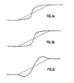
- the method according to the invention is characterized in that said processing is a polynomial transformation tending to replace x by a polynomial P (x) when x is less than 1/2 and x by the polynomial 1-P (1-x) when x is between 1/2 and 1 or equal to one of these two values.
- the object of the processing to be carried out is an image in the form of a table whose rows represent the samples in the horizontal direction and the columns the samples in the direction vertical, the contour reinforcement being carried out in one of these two directions.
- the input signal is sampled with a sufficiently high sampling frequency in front of its bandwidth, so that the transitions of the signal are made on a sufficient number of points (at least 4 or 5 for example).
- the contour reinforcement method according to the invention is then as follows.
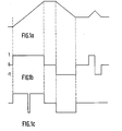
- the sign of the derivative of the signal is first calculated from the difference between two successive samples ( X n-1, x n ), this sign being expressed by 1, 0, or -1 depending on whether said difference xn - xn-1 is positive, zero or negative.
- the sign of the derivative is given by the curve in FIG. 1b.
- an upper limitation is imposed on the signals in time slots thus obtained to avoid abruptly straightening areas comprising smooth transitions on a large number of points, for example areas where there is a gradual transition from shadow to the light. It is this division into two shorter slots which is carried out on the left-hand side of FIG. 1 c.
- an operation known as normalization of the transitions is carried out, intended to bring the value of the first point to 0 and that of the last point to 1.
- a polynomial transformation is carried out, the polynomials that can be used can be very varied to adapt to the case to be treated, or even a transformation using other functions such as that exponentials, Arctangentes, etc ...
- a denormalization operation reverse of the previous normalization operation, to recover the initial dynamics, then we ensure the multiplexing of the samples processed during the signal transition period and those, unprocessed, which are located before or after this period, in order to find a complete signal.
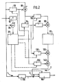
- FIG. 2 showing an embodiment of a device for implementing the method in the case of this application.
- the processing is applied in the horizontal direction, that is to say along the scanning lines of the image analysis system, with, in the example described, a sampling frequency of the difference signals color of 13.5 megahertz and a bandwidth of these signals of about one fifth of this value.
- the device of FIG. 2 firstly comprises a circuit (10, 20, 30) for calculating the sign of the derivative of the input signal, composed of a first delay circuit 10, a first subtractor 20 and of a control logic circuit 30.
- the delay circuit 10 delays said input signal by a sampling period T, and the subtractor 20 receives on the one hand the output xn-i of the delay circuit 10 and d on the other hand directly the input signal xn.
- the logic control circuit 30, which receives the output of the subtractor 20, then generates slots corresponding to the transitions of the input signal and of amplitude +1 or -1 depending on whether the sign of x n - l -x n is positive or negative.
- the circuit 30 segments those of these slots which have a duration greater than another threshold fixed at ten sampling periods, this segmentation being effected in as many segments as necessary so that none exceeds the fixed threshold. Finally, this circuit 30 generates the different read or write orders from the memories or registers used throughout the device.
- This device then comprises a standardization circuit (50, 60, 70, 80, 90, 100).
- This normalization circuit itself comprises a first "1 point” memory 50, which stores the value of the first point of the transition, and a second subtractor 60, which subtracts this value from that of all the following samples.
- the normalization circuit also includes, at the output of the subtractor 60, a second “1 point” memory 70 which stores the value of the difference between the last and the first point of the transition, a read only memory 80, which provides the inverse of this stored value, and a first multiplier 90 of this value reverses by each of the output values of the subtractor 60 transmitted to the other input of the multiplier via a second delay circuit 100 playing a role of time compensation transit.
- the normalized signal first by action of elements 50 and 60 then by action of elements 70 to 100, is available at the output of multiplier 90.
- the device according to the invention finally comprises, at the output of the memory 110, a denormalization circuit (120, 130, 140, 150), which makes it possible to recover the initial dynamics of the signal.
- This denormalization circuit includes for this purpose a multiplier 120 of the output of memory 110 by that of a first register 130 which had kept in memory, for this multiplication, the value of the last point of the transition used by the second memory "1 point" 70 for the normalization operation, then an adder 140 of the output of the multiplier 120 and that of a second register 150 having kept in memory the value of the first point of the transition (value which had been initially stored in the first "1 point” memory 50).
- the output of the adder 140 which delivers the denormalized signal, is sent to a multiplexer 160 which also receives the output of a third delay circuit 170 receiving and storing the input samples and having, like the circuit 100, a transit time compensation role.
- This multiplexer 160 ensures the multiplexing of the unprocessed points, situated before and after the transition processed, and which are transmitted to it by the transfer channel 1, and of the points treated using elements 10 to 150, which are transmitted to it by the parallel transfer channel 2.
- the output of the multiplexer 160 therefore delivers the signal with reinforced contours relative to the input signal.
- control connections connect the logic control circuit to the first "1 point” memory 50, to the second "1 point” memory 70, to the third delay circuit 100, to register 130, to register 150, and to the multiplexer 160, for good synchronization of the different operations.
- the invention is applicable in a very general way for the improvement of the subjective quality of any image or representation at least two-dimensional, that is to say not only in the field of television but also in medical or infrared imagery for example.
- polynomial transformation described as an essential operation of the processing according to the invention is not the only type of transformation possible, other modes of transformation based on logarithms, exponentials, trigonometric functions, etc. , which can of course be envisaged while respecting the symmetry with respect to point 1/2.
Landscapes
- Engineering & Computer Science (AREA)
- Multimedia (AREA)
- Signal Processing (AREA)
- Physics & Mathematics (AREA)
- General Physics & Mathematics (AREA)
- Theoretical Computer Science (AREA)
- Picture Signal Circuits (AREA)
- Television Systems (AREA)
- Processing Of Color Television Signals (AREA)
Claims (3)
Applications Claiming Priority (2)
| Application Number | Priority Date | Filing Date | Title |
|---|---|---|---|
| FR8603425A FR2595891B1 (fr) | 1986-03-11 | 1986-03-11 | Procede de renforcement des contours de signaux numeriques et dispositif de traitement pour la mise en oeuvre dudit procede |
| FR8603425 | 1986-03-11 |
Publications (2)
| Publication Number | Publication Date |
|---|---|
| EP0237115A1 EP0237115A1 (de) | 1987-09-16 |
| EP0237115B1 true EP0237115B1 (de) | 1990-05-23 |
Family
ID=9332988
Family Applications (1)
| Application Number | Title | Priority Date | Filing Date |
|---|---|---|---|
| EP87200362A Expired - Lifetime EP0237115B1 (de) | 1986-03-11 | 1987-03-02 | Verfahren zur Flankenversteilerung von digitalen Signalen und Vorrichtung zum Durchführen dieses Verfahrens |
Country Status (6)
| Country | Link |
|---|---|
| US (1) | US4839836A (de) |
| EP (1) | EP0237115B1 (de) |
| JP (1) | JP2505798B2 (de) |
| DE (1) | DE3762930D1 (de) |
| FI (1) | FI82345C (de) |
| FR (1) | FR2595891B1 (de) |
Families Citing this family (24)
| Publication number | Priority date | Publication date | Assignee | Title |
|---|---|---|---|---|
| JP2852390B2 (ja) * | 1991-02-16 | 1999-02-03 | 株式会社半導体エネルギー研究所 | 表示装置 |
| KR0130814B1 (en) * | 1993-12-18 | 1998-04-11 | Samsung Electronics Co Ltd | A contour correction method and apparatus of video signal |
| BR9609484A (pt) | 1995-07-16 | 1999-12-14 | Yoav Paltieli | Processo e aparelho para direcionamento à mão livre de uma agulha so sentido de um alvo localizado em um volume corpóreo e aparelho de agulha |
| DE19722358A1 (de) * | 1997-05-28 | 1998-12-03 | Thomson Brandt Gmbh | Verfahren zur Bearbeitung von Übergangsbereichen in einem Bildsignal |
| JPH11305743A (ja) | 1998-04-23 | 1999-11-05 | Semiconductor Energy Lab Co Ltd | 液晶表示装置 |
| EP1723780A1 (de) * | 2004-03-02 | 2006-11-22 | Koninklijke Philips Electronics N.V. | Signalverarbeitungssystem |
| US7728868B2 (en) | 2006-08-02 | 2010-06-01 | Inneroptic Technology, Inc. | System and method of providing real-time dynamic imagery of a medical procedure site using multiple modalities |
| US20080229370A1 (en) * | 2007-03-13 | 2008-09-18 | Zustak Frederick J | TV-centric system |
| WO2009094646A2 (en) | 2008-01-24 | 2009-07-30 | The University Of North Carolina At Chapel Hill | Methods, systems, and computer readable media for image guided ablation |
| US8340379B2 (en) * | 2008-03-07 | 2012-12-25 | Inneroptic Technology, Inc. | Systems and methods for displaying guidance data based on updated deformable imaging data |
| US11464578B2 (en) | 2009-02-17 | 2022-10-11 | Inneroptic Technology, Inc. | Systems, methods, apparatuses, and computer-readable media for image management in image-guided medical procedures |
| US8554307B2 (en) | 2010-04-12 | 2013-10-08 | Inneroptic Technology, Inc. | Image annotation in image-guided medical procedures |
| US8641621B2 (en) | 2009-02-17 | 2014-02-04 | Inneroptic Technology, Inc. | Systems, methods, apparatuses, and computer-readable media for image management in image-guided medical procedures |
| US8690776B2 (en) | 2009-02-17 | 2014-04-08 | Inneroptic Technology, Inc. | Systems, methods, apparatuses, and computer-readable media for image guided surgery |
| US8670816B2 (en) | 2012-01-30 | 2014-03-11 | Inneroptic Technology, Inc. | Multiple medical device guidance |
| US10314559B2 (en) | 2013-03-14 | 2019-06-11 | Inneroptic Technology, Inc. | Medical device guidance |
| US9901406B2 (en) | 2014-10-02 | 2018-02-27 | Inneroptic Technology, Inc. | Affected region display associated with a medical device |
| US10188467B2 (en) | 2014-12-12 | 2019-01-29 | Inneroptic Technology, Inc. | Surgical guidance intersection display |
| US10192162B2 (en) | 2015-05-21 | 2019-01-29 | Google Llc | Vector computation unit in a neural network processor |
| US9949700B2 (en) | 2015-07-22 | 2018-04-24 | Inneroptic Technology, Inc. | Medical device approaches |
| US9675319B1 (en) | 2016-02-17 | 2017-06-13 | Inneroptic Technology, Inc. | Loupe display |
| US10278778B2 (en) | 2016-10-27 | 2019-05-07 | Inneroptic Technology, Inc. | Medical device navigation using a virtual 3D space |
| US11259879B2 (en) | 2017-08-01 | 2022-03-01 | Inneroptic Technology, Inc. | Selective transparency to assist medical device navigation |
| US11484365B2 (en) | 2018-01-23 | 2022-11-01 | Inneroptic Technology, Inc. | Medical image guidance |
Family Cites Families (6)
| Publication number | Priority date | Publication date | Assignee | Title |
|---|---|---|---|---|
| US3800077A (en) * | 1971-10-15 | 1974-03-26 | Columbia Broadcasting Syst Inc | Automatic sharpness-enhancing equipment for television picture signals |
| NL7506411A (nl) * | 1975-05-30 | 1976-12-02 | Philips Corp | Signaaluitvalkompensatie-inrichting. |
| US4232340A (en) * | 1979-06-01 | 1980-11-04 | Rca Corporation | Defect compensation for color television |
| US4587620A (en) * | 1981-05-09 | 1986-05-06 | Nippon Gakki Seizo Kabushiki Kaisha | Noise elimination device |
| US4398210A (en) * | 1981-06-22 | 1983-08-09 | Rca Corporation | Impulse noise detection circuit for TV signals |
| KR890004853B1 (ko) * | 1985-01-28 | 1989-11-29 | 미쓰비시전기 주식회사 | 영상신호 처리회로 |
-
1986
- 1986-03-11 FR FR8603425A patent/FR2595891B1/fr not_active Expired
-
1987
- 1987-03-02 DE DE8787200362T patent/DE3762930D1/de not_active Expired - Lifetime
- 1987-03-02 EP EP87200362A patent/EP0237115B1/de not_active Expired - Lifetime
- 1987-03-06 US US07/022,464 patent/US4839836A/en not_active Expired - Fee Related
- 1987-03-06 FI FI870995A patent/FI82345C/fi not_active IP Right Cessation
- 1987-03-11 JP JP62054291A patent/JP2505798B2/ja not_active Expired - Lifetime
Also Published As
| Publication number | Publication date |
|---|---|
| FI82345C (fi) | 1991-02-11 |
| JPS62289089A (ja) | 1987-12-15 |
| FI870995A0 (fi) | 1987-03-06 |
| EP0237115A1 (de) | 1987-09-16 |
| US4839836A (en) | 1989-06-13 |
| FR2595891A1 (fr) | 1987-09-18 |
| DE3762930D1 (de) | 1990-06-28 |
| FI870995A7 (fi) | 1987-09-12 |
| FI82345B (fi) | 1990-10-31 |
| JP2505798B2 (ja) | 1996-06-12 |
| FR2595891B1 (fr) | 1988-06-10 |
Similar Documents
| Publication | Publication Date | Title |
|---|---|---|
| EP0237115B1 (de) | Verfahren zur Flankenversteilerung von digitalen Signalen und Vorrichtung zum Durchführen dieses Verfahrens | |
| EP0712072B1 (de) | Verfahren zur Ausführung von modularen Reduktion nach der Montgomery-Methode | |
| EP0142439B1 (de) | Verfahren zur Kompression einer Folge digitaler Informationen und Vorrichtung dafür | |
| FR2750554A1 (fr) | Systeme a acces conditionnel et carte a puce permettant un tel acces | |
| EP0576359B1 (de) | Verfahren und Einrichtung zur entscheidungsrückgekoppelten Entzerrung für die blockweise Übertragung von Informationssymbolen | |
| EP0204603A1 (de) | Schnelle Rechnerschaltung für die direkte oder umgekehrte Cosinustransformation eines diskreten Signals | |
| EP0130263A1 (de) | Startverfahren für einen Echokompensationsfilter und dieses Verfahren anwendendes Nachrichtenübertragungssystem | |
| EP0054459B1 (de) | Einrichtung zum Bearbeiten logarithmischer Signale, Anwendung für ein Frequenzdiversity-Radar und Radar mit einer derartigen Einrichtung | |
| FR2736231A1 (fr) | Systeme de communication numerique comportant un recepteur dote d'un dispositif de recuperation de rythme | |
| EP0262032A1 (de) | Binärer Addierer mit festem Operand und paralleler/serieller Multiplikator mit solchen Addierern | |
| EP0667969A1 (de) | ELEKTRONISCHE BERECHNUNGSEINRICHTUNG FüR DIE FOURIER TRANSFORMATION UND VERFAHREN ZUR MINIMISIERUNG DER INTERNEN DATENWEGE DIESER VORRICHTUNG | |
| EP0224957A1 (de) | Verfahren und Einrichtung zur Bewegungsabschätzung in einer Bildfolge | |
| EP0126495B1 (de) | Entzerrer für durch zyklische Verwechslung verschlüsselte Fernsehbilder | |
| EP0063990B1 (de) | Verfahren zur Bildübertragung mit beschränktem Datafluss; Übertragungssystem zur Durchführung dieses Verfahrens | |
| EP0085600A1 (de) | Einrichtung zur Entzerrung der durch einen Hochfrequenzsignalverstärker mit Spitzenwertregelung erzeugten Intermodulation | |
| FR2613893A1 (fr) | Procede de commutation de signaux numeriques asynchrones, et dispositif pour la mise en oeuvre de ce procede | |
| FR2546693A1 (fr) | Annuleur d'echo a filtre numerique adaptatif pour systeme de transmission | |
| FR2786632A1 (fr) | Procede et dispositif d'alignement de phase a grande vitesse | |
| EP0123573A1 (de) | Verfahren zum adaptiven Kodieren und Dekodieren eines Fernsehbildes und Vorrichtung zur Durchführung dieses Verfahrens | |
| EP0325509A1 (de) | Einrichtung zur blockweisen Fernsehzeilenpermutation | |
| EP0786920A1 (de) | Übertragungssystem für in Wechselbeziehung stehende Signale | |
| EP0585434A1 (de) | Filterverfahren und -einrichtung zur verringerung der vorechos in einem digitalen audiosignal | |
| EP0370152B1 (de) | Verfahren und Vorrichtung zur digitalen Datenübertragung | |
| FR2550403A1 (fr) | Procede de discrimination des contours et des textures dans une image video et dispositif detecteur de contour pour la mise en oeuvre de ce procede | |
| FR2683689A1 (fr) | Procede d'egalisation frequentielle d'un canal de transmission numerique et emetteur et recepteur pour la mise en óoeuvre du procede. |
Legal Events
| Date | Code | Title | Description |
|---|---|---|---|
| PUAI | Public reference made under article 153(3) epc to a published international application that has entered the european phase |
Free format text: ORIGINAL CODE: 0009012 |
|
| AK | Designated contracting states |
Kind code of ref document: A1 Designated state(s): DE FR GB IT SE |
|
| 17P | Request for examination filed |
Effective date: 19880315 |
|
| 17Q | First examination report despatched |
Effective date: 19890728 |
|
| RAP1 | Party data changed (applicant data changed or rights of an application transferred) |
Owner name: N.V. PHILIPS' GLOEILAMPENFABRIEKEN Owner name: LABORATOIRES D'ELECTRONIQUE PHILIPS |
|
| GRAA | (expected) grant |
Free format text: ORIGINAL CODE: 0009210 |
|
| AK | Designated contracting states |
Kind code of ref document: B1 Designated state(s): DE FR GB IT SE |
|
| PG25 | Lapsed in a contracting state [announced via postgrant information from national office to epo] |
Ref country code: SE Effective date: 19900523 |
|
| REF | Corresponds to: |
Ref document number: 3762930 Country of ref document: DE Date of ref document: 19900628 |
|
| ITF | It: translation for a ep patent filed | ||
| GBT | Gb: translation of ep patent filed (gb section 77(6)(a)/1977) | ||
| PLBE | No opposition filed within time limit |
Free format text: ORIGINAL CODE: 0009261 |
|
| STAA | Information on the status of an ep patent application or granted ep patent |
Free format text: STATUS: NO OPPOSITION FILED WITHIN TIME LIMIT |
|
| 26N | No opposition filed | ||
| ITTA | It: last paid annual fee | ||
| ITPR | It: changes in ownership of a european patent |
Owner name: CAMBIO RAGIONE SOCIALE;PHILIPS ELECTRONICS N.V. |
|
| REG | Reference to a national code |
Ref country code: FR Ref legal event code: CJ Ref country code: FR Ref legal event code: CD |
|
| PGFP | Annual fee paid to national office [announced via postgrant information from national office to epo] |
Ref country code: GB Payment date: 19960229 Year of fee payment: 10 |
|
| PGFP | Annual fee paid to national office [announced via postgrant information from national office to epo] |
Ref country code: FR Payment date: 19960327 Year of fee payment: 10 |
|
| PGFP | Annual fee paid to national office [announced via postgrant information from national office to epo] |
Ref country code: DE Payment date: 19960523 Year of fee payment: 10 |
|
| PG25 | Lapsed in a contracting state [announced via postgrant information from national office to epo] |
Ref country code: GB Effective date: 19970302 |
|
| GBPC | Gb: european patent ceased through non-payment of renewal fee |
Effective date: 19970302 |
|
| PG25 | Lapsed in a contracting state [announced via postgrant information from national office to epo] |
Ref country code: FR Free format text: LAPSE BECAUSE OF NON-PAYMENT OF DUE FEES Effective date: 19971128 |
|
| PG25 | Lapsed in a contracting state [announced via postgrant information from national office to epo] |
Ref country code: DE Effective date: 19971202 |
|
| REG | Reference to a national code |
Ref country code: FR Ref legal event code: ST |
|
| PG25 | Lapsed in a contracting state [announced via postgrant information from national office to epo] |
Ref country code: IT Free format text: LAPSE BECAUSE OF NON-PAYMENT OF DUE FEES;WARNING: LAPSES OF ITALIAN PATENTS WITH EFFECTIVE DATE BEFORE 2007 MAY HAVE OCCURRED AT ANY TIME BEFORE 2007. THE CORRECT EFFECTIVE DATE MAY BE DIFFERENT FROM THE ONE RECORDED. Effective date: 20050302 |