EP0237115B1 - Method for sharpening the transitions of digital signals, and device carrying out said method - Google Patents
Method for sharpening the transitions of digital signals, and device carrying out said method Download PDFInfo
- Publication number
- EP0237115B1 EP0237115B1 EP87200362A EP87200362A EP0237115B1 EP 0237115 B1 EP0237115 B1 EP 0237115B1 EP 87200362 A EP87200362 A EP 87200362A EP 87200362 A EP87200362 A EP 87200362A EP 0237115 B1 EP0237115 B1 EP 0237115B1
- Authority
- EP
- European Patent Office
- Prior art keywords
- value
- output
- circuit
- signal
- input
- Prior art date
- Legal status (The legal status is an assumption and is not a legal conclusion. Google has not performed a legal analysis and makes no representation as to the accuracy of the status listed.)
- Expired - Lifetime
Links
- 230000007704 transition Effects 0.000 title claims description 41
- 238000000034 method Methods 0.000 title claims description 22
- 230000015654 memory Effects 0.000 claims description 24
- 230000009466 transformation Effects 0.000 claims description 24
- 230000006870 function Effects 0.000 claims description 9
- 238000010606 normalization Methods 0.000 claims description 9
- 238000005070 sampling Methods 0.000 claims description 7
- 230000000694 effects Effects 0.000 claims description 2
- 230000001131 transforming effect Effects 0.000 claims 1
- 230000001052 transient effect Effects 0.000 claims 1
- 235000021183 entrée Nutrition 0.000 description 8
- 230000002787 reinforcement Effects 0.000 description 6
- 238000005728 strengthening Methods 0.000 description 3
- 238000000844 transformation Methods 0.000 description 3
- 230000009471 action Effects 0.000 description 2
- 230000003014 reinforcing effect Effects 0.000 description 2
- 230000011218 segmentation Effects 0.000 description 2
- 238000006677 Appel reaction Methods 0.000 description 1
- 240000008042 Zea mays Species 0.000 description 1
- 230000003044 adaptive effect Effects 0.000 description 1
- 230000001934 delay Effects 0.000 description 1
- 238000010191 image analysis Methods 0.000 description 1
- 230000006872 improvement Effects 0.000 description 1
- 230000008569 process Effects 0.000 description 1
Images
Classifications
-
- G06T5/73—
-
- H—ELECTRICITY
- H04—ELECTRIC COMMUNICATION TECHNIQUE
- H04N—PICTORIAL COMMUNICATION, e.g. TELEVISION
- H04N5/00—Details of television systems
- H04N5/14—Picture signal circuitry for video frequency region
- H04N5/142—Edging; Contouring
-
- G—PHYSICS
- G06—COMPUTING; CALCULATING OR COUNTING
- G06T—IMAGE DATA PROCESSING OR GENERATION, IN GENERAL
- G06T2207/00—Indexing scheme for image analysis or image enhancement
- G06T2207/10—Image acquisition modality
- G06T2207/10016—Video; Image sequence
-
- G—PHYSICS
- G06—COMPUTING; CALCULATING OR COUNTING
- G06T—IMAGE DATA PROCESSING OR GENERATION, IN GENERAL
- G06T2207/00—Indexing scheme for image analysis or image enhancement
- G06T2207/20—Special algorithmic details
- G06T2207/20172—Image enhancement details
- G06T2207/20192—Edge enhancement; Edge preservation
Definitions
- the present invention relates to a method for reinforcing signal transitions comprising a transition zone between zones of low amplitude and high amplitude and operating by multiplexing of samples processed during the duration of said transition zone and of non-samples processed for the parts of signals situated outside the said zone.
- the invention also relates to a processing device for implementing the method according to claim 1, comprising means for multiplexing the samples of the input signal processed during the duration of the transition zone and the unprocessed samples located outside of said area.
- These methods and device are applicable in particular to the reinforcement of the contours of images and very particularly to the reinforcement of the contours of chrominance or of luminance in the case of television images, for example when receiving video signals coded according to a MAC standard, to improve the subjective quality of the image.
- An object of the invention is to propose a method for reinforcing the contours aiming, more broadly, at improving the subjective quality of the signal by replacing the part of it situated in the transition zone.
- the invention relates to a method as indicated above and characterized in that it comprises, prior to said multiplexing, essentially the following operations:
- This method according to the invention does not just make the transitions stiffer, but offers the possibility of modulating at will the effect of strengthening the transitions.
- the method according to the invention is characterized in that said processing is a polynomial transformation tending to replace x by a polynomial P (x) when x is less than 1/2 and x by the polynomial 1-P (1-x) when x is between 1/2 and 1 or equal to one of these two values.
- the object of the processing to be carried out is an image in the form of a table whose rows represent the samples in the horizontal direction and the columns the samples in the direction vertical, the contour reinforcement being carried out in one of these two directions.
- the input signal is sampled with a sufficiently high sampling frequency in front of its bandwidth, so that the transitions of the signal are made on a sufficient number of points (at least 4 or 5 for example).
- the contour reinforcement method according to the invention is then as follows.
- the sign of the derivative of the signal is first calculated from the difference between two successive samples ( X n-1, x n ), this sign being expressed by 1, 0, or -1 depending on whether said difference xn - xn-1 is positive, zero or negative.
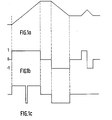
- the sign of the derivative is given by the curve in FIG. 1b.
- an upper limitation is imposed on the signals in time slots thus obtained to avoid abruptly straightening areas comprising smooth transitions on a large number of points, for example areas where there is a gradual transition from shadow to the light. It is this division into two shorter slots which is carried out on the left-hand side of FIG. 1 c.
- an operation known as normalization of the transitions is carried out, intended to bring the value of the first point to 0 and that of the last point to 1.
- a polynomial transformation is carried out, the polynomials that can be used can be very varied to adapt to the case to be treated, or even a transformation using other functions such as that exponentials, Arctangentes, etc ...
- a denormalization operation reverse of the previous normalization operation, to recover the initial dynamics, then we ensure the multiplexing of the samples processed during the signal transition period and those, unprocessed, which are located before or after this period, in order to find a complete signal.
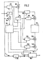
- FIG. 2 showing an embodiment of a device for implementing the method in the case of this application.
- the processing is applied in the horizontal direction, that is to say along the scanning lines of the image analysis system, with, in the example described, a sampling frequency of the difference signals color of 13.5 megahertz and a bandwidth of these signals of about one fifth of this value.
- the device of FIG. 2 firstly comprises a circuit (10, 20, 30) for calculating the sign of the derivative of the input signal, composed of a first delay circuit 10, a first subtractor 20 and of a control logic circuit 30.
- the delay circuit 10 delays said input signal by a sampling period T, and the subtractor 20 receives on the one hand the output xn-i of the delay circuit 10 and d on the other hand directly the input signal xn.
- the logic control circuit 30, which receives the output of the subtractor 20, then generates slots corresponding to the transitions of the input signal and of amplitude +1 or -1 depending on whether the sign of x n - l -x n is positive or negative.
- the circuit 30 segments those of these slots which have a duration greater than another threshold fixed at ten sampling periods, this segmentation being effected in as many segments as necessary so that none exceeds the fixed threshold. Finally, this circuit 30 generates the different read or write orders from the memories or registers used throughout the device.
- This device then comprises a standardization circuit (50, 60, 70, 80, 90, 100).
- This normalization circuit itself comprises a first "1 point” memory 50, which stores the value of the first point of the transition, and a second subtractor 60, which subtracts this value from that of all the following samples.
- the normalization circuit also includes, at the output of the subtractor 60, a second “1 point” memory 70 which stores the value of the difference between the last and the first point of the transition, a read only memory 80, which provides the inverse of this stored value, and a first multiplier 90 of this value reverses by each of the output values of the subtractor 60 transmitted to the other input of the multiplier via a second delay circuit 100 playing a role of time compensation transit.
- the normalized signal first by action of elements 50 and 60 then by action of elements 70 to 100, is available at the output of multiplier 90.
- the device according to the invention finally comprises, at the output of the memory 110, a denormalization circuit (120, 130, 140, 150), which makes it possible to recover the initial dynamics of the signal.
- This denormalization circuit includes for this purpose a multiplier 120 of the output of memory 110 by that of a first register 130 which had kept in memory, for this multiplication, the value of the last point of the transition used by the second memory "1 point" 70 for the normalization operation, then an adder 140 of the output of the multiplier 120 and that of a second register 150 having kept in memory the value of the first point of the transition (value which had been initially stored in the first "1 point” memory 50).
- the output of the adder 140 which delivers the denormalized signal, is sent to a multiplexer 160 which also receives the output of a third delay circuit 170 receiving and storing the input samples and having, like the circuit 100, a transit time compensation role.
- This multiplexer 160 ensures the multiplexing of the unprocessed points, situated before and after the transition processed, and which are transmitted to it by the transfer channel 1, and of the points treated using elements 10 to 150, which are transmitted to it by the parallel transfer channel 2.
- the output of the multiplexer 160 therefore delivers the signal with reinforced contours relative to the input signal.
- control connections connect the logic control circuit to the first "1 point” memory 50, to the second "1 point” memory 70, to the third delay circuit 100, to register 130, to register 150, and to the multiplexer 160, for good synchronization of the different operations.
- the invention is applicable in a very general way for the improvement of the subjective quality of any image or representation at least two-dimensional, that is to say not only in the field of television but also in medical or infrared imagery for example.
- polynomial transformation described as an essential operation of the processing according to the invention is not the only type of transformation possible, other modes of transformation based on logarithms, exponentials, trigonometric functions, etc. , which can of course be envisaged while respecting the symmetry with respect to point 1/2.
Description
La présente invention concerne un procédé de renforcement de transitions de signaux comportant une zone de transition entre des zones d'amplitude faible et d'amplitude élevée et opérant par multiplexage d'échantillons traités pendant la durée de ladite zone de transition et d'échantillons non traités pour les parties de signaux situées hors de ladite zone.The present invention relates to a method for reinforcing signal transitions comprising a transition zone between zones of low amplitude and high amplitude and operating by multiplexing of samples processed during the duration of said transition zone and of non-samples processed for the parts of signals situated outside the said zone.
L'invention concerne également un dispositif de traitement pour la mise en oeuvre du procédé selon la revendication 1, comprenant des moyens de multiplexage des échantillons du signal d'entrée traités pendant la durée de la zone de transition et des échantillons non traités situés hors de ladite zone.The invention also relates to a processing device for implementing the method according to
Ces procédé et dispositif sont applicables notamment au renforcement des contours d'images et tout particulièrement au renforcement des contours de chrominance ou de luminance dans le cas d'images de télévision, par exemple lors de la réception de signaux vidéofréquence codés selon un standard MAC, pour améliorer la qualité subjective de l'image.These methods and device are applicable in particular to the reinforcement of the contours of images and very particularly to the reinforcement of the contours of chrominance or of luminance in the case of television images, for example when receiving video signals coded according to a MAC standard, to improve the subjective quality of the image.
Un procédé et un dispositif de ce type sont décrits sur la figure 8 de l'article "Adaptive Techniken bei der digitalen Videosignalverarbeitung in Farb- fernsehempfângern" de M. Jacobsen, paru dans la revue Fernseh- und Kinotechnik, n°6/1983, pages 245-250. Mais il apparaît en fait que ce procédé réalise seulement un redressement du flanc de transition du signal, par interpolation à partir de quelques points de celui-ci.A process and a device of this type are described in FIG. 8 of the article "Adaptive Techniken bei der digitalen Videosignalverarbeitung in Farb- fernsehempfângern" by M. Jacobsen, published in the review Fernseh- und Kinotechnik, n ° 6/1983, pages 245-250. But it appears in fact that this method only achieves a straightening of the signal transition edge, by interpolation from a few points thereof.
Un but de l'invention est de proposer un procédé de renforcement des contours visant, de façon plus large, à améliorer la qualité subjective du signal par un remplacement de la partie de celui-ci située dans la zone de transition.An object of the invention is to propose a method for reinforcing the contours aiming, more broadly, at improving the subjective quality of the signal by replacing the part of it situated in the transition zone.
A cet effet, l'invention concerne un procédé comme indiqué ci-dessus et caractérisé en ce qu'il comprend, préalablement audit multiplexage, essentiellement les opérations suivantes :To this end, the invention relates to a method as indicated above and characterized in that it comprises, prior to said multiplexing, essentially the following operations:
- - normalisation du signal d'entrée pendant la durée de la zone de transition, destinée à ramener la valeur du premier point d'échantillonnage à 0 et celle du dernier point à 1 ;normalization of the input signal during the duration of the transition zone, intended to bring the value of the first sampling point to 0 and that of the last point to 1;
-
- traitement de transformation destiné à remplacer la valeur de chaque échantillon de la zone de transition par une autre valeur selon une fonction de transformation déterminée indépendante des valeurs du signal en dehors de la zone de transition et symétrique par rapport au point 1/2.transformation processing intended to replace the value of each sample of the transition zone by another value according to a determined transformation function independent of the values of the signal outside the transition zone and symmetrical with respect to the
point 1/2. - - dénormalisation du signal ainsi transformé pour retrouver la dynamique initiale du signal d'entrée.- denormalization of the signal thus transformed to recover the initial dynamics of the input signal.
Ce procédé selon l'invention ne se contente ps de rendre des transitions plus raides, mais offre la possibilité de moduler à volonté l'effet de renforcement des transitions.This method according to the invention does not just make the transitions stiffer, but offers the possibility of modulating at will the effect of strengthening the transitions.
Dans un mode particulier de sa mise en oeuvre, le procédé selon l'invention est caractérisé en ce que ledit traitement est une transformation polynomiale tendant à remplacer x par un polynôme P(x) lorsque x est inférieur à 1/2 et x par le polynôme 1-P(1-x) lorsque x est compris entre 1/2 et 1 ou égal à l'une de ces deux valeurs.In a particular mode of its implementation, the method according to the invention is characterized in that said processing is a polynomial transformation tending to replace x by a polynomial P (x) when x is less than 1/2 and x by the polynomial 1-P (1-x) when x is between 1/2 and 1 or equal to one of these two values.
Un autre but de l'invention est de proposer un dispositif avantageux de mise en oeuvre de ce procédé:Another object of the invention is to propose an advantageous device for implementing this method:
L'invention concerne à cet effet un dispositif de traitement comme indiqué ci-dessus et caractérisé en ce que lesdits moyens de multiplexage sont précédés d'une première voie de transfert des échantillons d'entrée non traités et, en parallèle sur celle-ci, d'une deuxième voie de transfert des échantillons d'entrée traités, ladite deuxième voie de transfert comprenant elle-même :
- (1) un circuit de calcul du signe de la dérivée du signal d'entrée, composé :
- (a) d'un premier circuit à retard retardant le signal d'entrée d'une période d'échantillonnage T ;
- (b) d'un premier soustracteur recevant d'une part la sortie Xn-1 du premier circuit à retard sur son entrée positive et d'autre part directement l'échantillon d'entrée xn sur son entrée négative ;
- (c) d'un circuit logique de commande recevant la sortie dudit soustracteur et délivrant des créneaux correspondant aux transitions du signal d'entrée et d'amplitude opposée selon que le signe de Xn-1-Xn est positif ou négatif ;
- (2) un circuit de normalisation composé :
- (d) d'une part, d'une première mémoire "1 point", qui stocke la valeur du premier point de la zone de transition, et d'un deuxième soustracteur retranchant cette valeur de celle de tous les échantillons suivants, qui arrive directement sur l'autre entrée de ce soustracteur ;
- (e) d'autre part, en sortie de ce deuxième soustracteur, d'une deuxième mémoire "1 point" stockant la valeur du dernier point de la zone de transition, d'un circuit d'inversion de ladite valeur, d'un premier multiplieur de cette valeur inverse par chacune des valeurs de sortie du deuxième soustracteur transmises à l'autre entrée dudit multiplieur par l'intermédiaire d'un deuxième circuit à retard ;
- (3) un circuit de transformation de chaque valeur de sortie x du premier multiplieur par un polynôme P(x) ou une fonction F(x) si x n'est pas supérieur à 1/2, ou par un polynôme 1 - P(1-x) ou une fonction 1 - F(1-x) si x est supérieur à 1/2 ;
- (4) un circuit de dénormalisation composé :
- (f) d'une part, d'un deuxième multiplieur recevant la sortie du circuit de transformation et celle d'un premier registre de stockage de la valeur précédemment stockée dans la deuxième mémoire "1 point" ;
- (g) d'autre part, d'un additionneur de la sortie dudit deuxième multiplieur et de la sortie d'un deuxième registre de stockage de la valeur précédemment stockée dans la première mémoire "1 point" ;
- la sortie dudit additionneur constituant la sortie de la deuxième voie de transfert, et le circuit logique de commande délivrant les différents ordres de lecture ou d'écriture des mémoires ou registres du dispositif.
- (1) a circuit for calculating the sign of the derivative of the input signal, composed of:
- (a) a first delay circuit delaying the input signal by a sampling period T;
- (b) a first subtractor receiving on the one hand the output Xn - 1 of the first delay circuit on its positive input and on the other hand directly the input sample x n on its negative input;
- (c) a logic control circuit receiving the output of said subtractor and delivering slots corresponding to the transitions of the input signal and of opposite amplitude depending on whether the sign of X n-1-X n is positive or negative;
- (2) a standardization circuit composed of:
- (d) on the one hand, a first memory "1 point", which stores the value of the first point of the transition zone, and a second subtractor subtracting this value from that of all the following samples, which arrives directly on the other input of this subtractor;
- (e) on the other hand, at the output of this second subtractor, a second "1 point" memory storing the value of the last point of the transition zone, a circuit for inverting said value, a first multiplier of this inverse value by each of the output values of the second subtractor transmitted to the other input of said multiplier via a second delay circuit;
- (3) a transformation circuit of each output value x of the first multiplier by a polynomial P (x) or a function F (x) if x is not greater than 1/2, or by a polynomial 1 - P ( 1-x) or a function 1 - F (1-x) if x is greater than 1/2;
- (4) a denormalization circuit composed:
- (f) on the one hand, a second multiplier receiving the output of the transformation circuit and that of a first register for storing the value previously stored in the second "1 point"memory;
- (g) on the other hand, an adder of the output of said second multiplier and of the output of a second storage register of the value previously stored in the first "1 point"memory;
- the output of said adder constituting the output of the second transfer channel, and the control logic circuit delivering the different read or write orders from the memories or registers of the device.
Les particularités et avantages de l'invention apparaîtront maintenant de façon plus précise dans la description qui suit et dans les dessins annexés, donnés à titre d'exemples non limitatifs et dans lesquels :
- - les figures 1a, 1b, 1c montrent respectivement un exemple de signal d'origine à traiter, la courbe correspondante -en créneaux- donnant le signe de la dérivée dudit signal d'origine, et cette même courbe du signe de la dérivée mais avec une limitation du premier créneau qui, trop long, a été divisé en deux créneaux plus courts ;
- - la figure 2 montre un exemple de réalisation de dispositif de traitement pour la mise en oeuvre du procédé selon l'invention ;
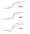
- - les figures 3a à 3c montrent trois exemples de renforcement de contours obtenus par des transformations polynomiales faisant appel à des polynômes respectivement du type en X2, en 2P-1 xP, et en ax3 + bx.
- - Figures 1a, 1b, 1c respectively show an example of an original signal to be processed, the corresponding curve -in slots- giving the sign of the derivative of said original signal, and this same curve of the sign of the derivative but with a limitation of the first slot which, being too long, has been divided into two shorter slots;
- - Figure 2 shows an exemplary embodiment of the processing device for implementing the method according to the invention;
- - Figures 3a to 3c show three examples of reinforcement of contours obtained by polynomial transformations using polynomials respectively of the type in X 2, in 2P- 1 xP, and in ax3 + bx.
On supposera tout d'abord, dans le cas présent, que l'objet du traitement à effectuer est une image se présentant sous la forme d'un tableau dont les lignes représentent les échantillons dans la direction horizontale et les colonnes les échantillons dans la direction verticale, le renforcement de contour étant effectué dans l'une de ces deux directions. On supposera aussi que le signal d'entrée est échantillonné avec une fréquence d'échantillonnage suffisamment importante devant sa bande passante, afin que les transitions du signal se fassent sur un nombre de points suffisant (au moins 4 ou 5 par exemple).First of all, it will be assumed, in the present case, that the object of the processing to be carried out is an image in the form of a table whose rows represent the samples in the horizontal direction and the columns the samples in the direction vertical, the contour reinforcement being carried out in one of these two directions. It will also be assumed that the input signal is sampled with a sufficiently high sampling frequency in front of its bandwidth, so that the transitions of the signal are made on a sufficient number of points (at least 4 or 5 for example).
Le procédé de renforcement de contour selon l'invention est alors le suivant. On calcule dans un premier temps le signe de la dérivée du signal, à partir de la différence entre deux échantillons successifs (Xn-1, xn), ce signe étant exprimé par 1, 0, ou -1 selon que ladite différence xn - xn-1 est positive, nulle ou négative. Pour un signal d'origine tel que celui représenté sur la figure 1a, 1e signe de la dérivée est donné par la courbe de la figure 1b. Dans un deuxième temps, on impose aux signaux en créneaux ainsi obtenus une limitation supérieure pour éviter de redresser brutalement des zones comportant des transitions douces sur un grand nombre de points, par exemple des zones où s'effectue un passage progressif de l'ombre à la lumière. C'est ce morcellement en deux créneaux plus brefs qui est réalisé sur la partie gauche de la figure 1 c. Dans un troisième temps, on effectue une opération dite de normalisation des transitions, destinée à ramener la valeur du premier point à 0 et celle du dernier point à 1.The contour reinforcement method according to the invention is then as follows. The sign of the derivative of the signal is first calculated from the difference between two successive samples ( X n-1, x n ), this sign being expressed by 1, 0, or -1 depending on whether said difference xn - xn-1 is positive, zero or negative. For an original signal such as that shown in FIG. 1a, the sign of the derivative is given by the curve in FIG. 1b. In a second step, an upper limitation is imposed on the signals in time slots thus obtained to avoid abruptly straightening areas comprising smooth transitions on a large number of points, for example areas where there is a gradual transition from shadow to the light. It is this division into two shorter slots which is carried out on the left-hand side of FIG. 1 c. Thirdly, an operation known as normalization of the transitions is carried out, intended to bring the value of the first point to 0 and that of the last point to 1.
Dans un quatrième temps, qui constitue l'étape essentielle du procédé selon l'invention, on opère une transformation polynomiale, les polynômes utilisables pouvant être très variés pour s'adapter au cas à traiter, ou même une transformation utilisant d'autres fonctions telles que des exponentielles, des Arctangentes, etc... Enfin, après une telle transformation, on effectue une opération de dénormalisation, inverse de l'opération de normalisation précédente, pour retrouver la dynamique initiale, puis on assure le multiplexage des échantillons traités pendant la période de transition du signal et de ceux, non traités, qui sont situés avant ou après cette.période, afin de retrouver un signal complet.In a fourth step, which constitutes the essential step of the method according to the invention, a polynomial transformation is carried out, the polynomials that can be used can be very varied to adapt to the case to be treated, or even a transformation using other functions such as that exponentials, Arctangentes, etc ... Finally, after such a transformation, we perform a denormalization operation, reverse of the previous normalization operation, to recover the initial dynamics, then we ensure the multiplexing of the samples processed during the signal transition period and those, unprocessed, which are located before or after this period, in order to find a complete signal.
On décrira maintenant une application particulière de ce procédé au renforcement des contours ou transitions en couleurs d'un signal de télévision codé selon le standard D2-MAC-paquets. Cette description est effectué en liaison avec la figure 2 montrant un mode de réalisation d'un dispositif de mise en oeuvre du procédé dans le cas de cette application. On précisera préalablement que le traitement est appliqué dans la direction horizontale, c'est-à-dire suivant les lignes de balayage du système d'analyse des images, avec, dans l'exemple décrit, une fréquence d'échantillonnage des signaux de différence de couleur de 13,5 mégahertz et une bande passante de ces signaux d'environ le cinquième de cette valeur. Ces caractéristiques ont conduit à une segmentation en n segments des transitions comportant un nombre de points supérieur à n x 10.We will now describe a particular application of this method to strengthening the contours or color transitions of a television signal coded according to the D2-MAC-packet standard. This description is made in conjunction with FIG. 2 showing an embodiment of a device for implementing the method in the case of this application. It will be specified beforehand that the processing is applied in the horizontal direction, that is to say along the scanning lines of the image analysis system, with, in the example described, a sampling frequency of the difference signals color of 13.5 megahertz and a bandwidth of these signals of about one fifth of this value. These characteristics have led to a segmentation into n segments of the transitions comprising a number of points greater than n × 10.
Le dispositif de la figure 2 comprend tout d'abord un circuit (10, 20, 30) de calcul du signe de la dérivée du signal d'entrée, composé d'un premier circuit à retard 10, d'un premier soustracteur 20 et d'un circuit logique de commande 30. Le circuit à retard 10 retarde ledit signal d'entrée d'une période d'échantillonnage T, et le soustracteur 20 reçoit d'une part la sortie xn-i du circuit à retard 10 et d'autre part directement le signal d'entrée xn. Le circuit logique de commande 30, qui reçoit la sortie du soustracteur 20, génère alors des créneaux correspondant aux transitions du signal d'entrée et d'amplitude +1 ou -1 selon que le signe de xn-l-xn est positif ou négatif. Simultanément, le circuit 30 segmente ceux de ces créneaux qui ont une durée supérieure à un autre seuil fixé à dix périodes d'échantillonnage, cette segmentation étant opérée en autant de segments que nécessaire pour qu'aucun ne dépasse le seuil fixé. Enfin, ce circuit 30 génère les différents ordres de lecture ou d'écriture des mémoires ou registres utilisés dans l'ensemble du dispositif.The device of FIG. 2 firstly comprises a circuit (10, 20, 30) for calculating the sign of the derivative of the input signal, composed of a
Ce dispositif comprend ensuite un circuit (50, 60, 70, 80, 90, 100) de normalisation. Ce circuit de normalisation comprend lui-même une première mémoire "1 point" 50, qui stocke la valeur du premier point de la transition, et un deuxième soustracteur 60, qui retranche cette valeur de celle de tous les échantillons suivants. Le circuit de normalisation comprend également, en sortie du soustracteur 60, une deuxième mémoire "1 point" 70 qui stocke la valeur de la différence entre le dernier et le premier point de la transition, une mémoire morte 80, qui fournit l'inverse de cette valeur stockée, et un premier multiplieur 90 de cette valeur inverse par chacune des valeurs de sortie du soustracteur 60 transmises à l'autre entrée du multiplieur par l'intermédiaire d'un deuxième circuit à retard 100 jouant un rôle de compensation de temps de transit. Le signal normalisé, d'abord par action des éléments 50 et 60 puis par action des éléments 70 à 100, est disponible en sortie du multiplieur 90.This device then comprises a standardization circuit (50, 60, 70, 80, 90, 100). This normalization circuit itself comprises a first "1 point"
A ce signal normalisé, c'est-à-dire maintenant compris entre 0 et 1, est alors appliquée une transformation polynomiale centrée sur le point d'amplitude 1/2. Dans l'exemple de réalisation ici décrit, le dispositif selon l'invention comprend une mémoire morte 110 de type PROM (de l'anglais Programmable Read-Only Memory) dont la programmation est réalisée à volonté, selon le cas particulier de renforcement de contour que l'on veut effectuer. Les figures 3a à 3c montrent trois exemples distincts de renforcement de contours, obtenus par application de trois types particuliers de transformations polynomiales (le contour d'origine est représenté en trait interrompu et le contour renforcé en trait continu) :
- (a) cas d'un polynôme en X 2 (figure 3a) : chaque valeur x est remplacée par x2 si x est nul ou compris entre 0
et 1/2, et par 1-(1-x)2 si x est compris entre 1/2et 1 ou égal à l'une de ces deux limites ; - (b) cas d'un polynôme en 2P-1xP (figure 3b): chaque valeur x est de façon similaire remplacée
par 2p-1xp ou par 1-2P-1(1-x)P selon la valeur de x ; - (c) cas d'un polynôme en ax3 + bx (figure 3c) : chaque valeur de x est, de même, remplacée par ax3 + bx ou par 1-(a(1-x)3 + b(1-x)) selon la valeur de x, avec des coefficients a et b qui ont par exemple été choisis égaux à a = 4/(1-12x2) et b = -3x2 , où xo est un coefficient dont la valeur détermine la plus ou moins grande importance du renforcement du contour.
- (a) case of a polynomial in X 2 (Figure 3a): each value x is replaced by x 2 if x is zero or between 0 and 1/2, and by 1- (1-x) 2 if x is between 1/2 and 1 or equal to one of these two limits;
- (b) case of a polynomial in 2P- 1 xP (figure 3b): each value x is similarly replaced by 2 p- 1x p or by 1-2P-1 (1-x) P according to the value of x ;
- (c) case of a polynomial in ax 3 + bx (figure 3c): each value of x is likewise replaced by ax 3 + bx or by 1- (a (1-x) 3 + b (1- x)) according to the value of x, with coefficients a and b which have for example been chosen equal to a = 4 / (1-12x 2 ) and b = -3x 2 , where xo is a coefficient whose value determines the more or less great importance of strengthening the contour.
Le dispositif selon l'invention comprend enfin, en sortie de la mémoire 110, un circuit de dénormalisation (120, 130, 140, 150), qui permet de retrouver la dynamique initiale du signal. Ce circuit de dénormalisation comprend à cet effet un multiplieur 120 de la sortie de la mémoire 110 par celle d'un premier registre 130 qui avait conservé en mémoire, en vue de cette multiplication, la valeur du dernier point de la transition utilisée par la deuxième mémoire "1 point" 70 pour l'opération de normalisation, puis un additionneur 140 de la sortie du multiplieur 120 et de celle d'un deuxième registre 150 ayant conservé en mémoire la valeur du premier point de la transition (valeur qui avait été initialement stockée dans la première mémoire "1 point" 50). La sortie de l'additionneur 140, qui délivre le signal dénormalisé, est envoyée vers un multiplexeur 160 qui reçoit par ailleurs la sortie d'un troisième circuit à retard 170 recevant et stockant les échantillons d'entrée et ayant, comme le circuit 100, un rôle de compensation de temps de transit. Ce multiplexeur 160 assure le multiplexage des points non traités, situés avant et après la transition traitée, et qui lui sont transmis par la voie de transfert 1, et des points traités à l'aide des éléments 10 à 150, qui lui sont transmis par la voie de transfert en parallèle 2. La sortie du multiplexeur 160 délivre donc le signal à contours renforcés par rapport au signal d'entrée.The device according to the invention finally comprises, at the output of the
Bien entendu, des connexions de commande relient le circuit logique de commande à la première mémoire "1 point" 50, à la deuxième mémoire "1 point" 70, au troisième circuit à retard 100, au registre 130, au registre 150, et au multiplexeur 160, pour la bonne synchronisation des différentes opérations.Of course, control connections connect the logic control circuit to the first "1 point"
L'invention qui vient d'être décrite n'est, manifestement, pas limitée au mode de réalisation expressément décrit et représenté, à partir duquel des variantes peuvent être proposées sans pour cela sortir du cadre de l'invention. Par exemple, les possibilités du circuit logique de commande 30 peuvent être élargies : on peut notamment demander à ce circuit d'éliminer du signal de commande de la transformation polynomiale les brefs créneaux successifs d'amplitude opposée (un exemple en est représenté sur la partie droite de la figure 1b) qui correspondent à des transitions brutales elles-mêmes dues à du bruit (la figure 1c ne comprend effectivement plus ces créneaux).The invention which has just been described is obviously not limited to the embodiment expressly described and shown, from which variants can be proposed without thereby departing from the scope of the invention. For example, the possibilities of the
Par ailleurs il est manifeste que l'invention est applicable de façon tout à fait générale pour l'amélioration de la qualité subjective de toute image ou représentation au moins bidimensionnelle, c'est-à-dire non seulement dans le domaine de la télévision mais aussi en imagerie médicale ou infrarouge par exemple.Furthermore, it is obvious that the invention is applicable in a very general way for the improvement of the subjective quality of any image or representation at least two-dimensional, that is to say not only in the field of television but also in medical or infrared imagery for example.
Enfin, la transformation polynomiale décrite comme une opération essentielle du traitement selon l'invention n'est pas le seul type de transformation possible, d'autres modes de transformation à base de logarithmes, d'exponentielles, de fonctions trigonométriques, etc..., pouvant bien entendu être envisagés tout en respectant la symétrie par rapport au point 1/2.Finally, the polynomial transformation described as an essential operation of the processing according to the invention is not the only type of transformation possible, other modes of transformation based on logarithms, exponentials, trigonometric functions, etc. , which can of course be envisaged while respecting the symmetry with respect to
Claims (3)
Applications Claiming Priority (2)
| Application Number | Priority Date | Filing Date | Title |
|---|---|---|---|
| FR8603425A FR2595891B1 (en) | 1986-03-11 | 1986-03-11 | METHOD FOR STRENGTHENING THE CONTOURS OF DIGITAL SIGNALS AND PROCESSING DEVICE FOR CARRYING OUT SAID METHOD |
| FR8603425 | 1986-03-11 |
Publications (2)
| Publication Number | Publication Date |
|---|---|
| EP0237115A1 EP0237115A1 (en) | 1987-09-16 |
| EP0237115B1 true EP0237115B1 (en) | 1990-05-23 |
Family
ID=9332988
Family Applications (1)
| Application Number | Title | Priority Date | Filing Date |
|---|---|---|---|
| EP87200362A Expired - Lifetime EP0237115B1 (en) | 1986-03-11 | 1987-03-02 | Method for sharpening the transitions of digital signals, and device carrying out said method |
Country Status (6)
| Country | Link |
|---|---|
| US (1) | US4839836A (en) |
| EP (1) | EP0237115B1 (en) |
| JP (1) | JP2505798B2 (en) |
| DE (1) | DE3762930D1 (en) |
| FI (1) | FI82345C (en) |
| FR (1) | FR2595891B1 (en) |
Families Citing this family (24)
| Publication number | Priority date | Publication date | Assignee | Title |
|---|---|---|---|---|
| JP2852390B2 (en) * | 1991-02-16 | 1999-02-03 | 株式会社半導体エネルギー研究所 | Display device |
| KR0130814B1 (en) * | 1993-12-18 | 1998-04-11 | Samsung Electronics Co Ltd | A contour correction method and apparatus of video signal |
| WO1997003609A1 (en) | 1995-07-16 | 1997-02-06 | Ultra-Guide Ltd. | Free-hand aiming of a needle guide |
| DE19722358A1 (en) * | 1997-05-28 | 1998-12-03 | Thomson Brandt Gmbh | Process for processing transition areas in an image signal |
| JPH11305743A (en) | 1998-04-23 | 1999-11-05 | Semiconductor Energy Lab Co Ltd | Liquid crystal display device |
| JP2007526707A (en) * | 2004-03-02 | 2007-09-13 | コーニンクレッカ フィリップス エレクトロニクス エヌ ヴィ | Signal processing system |
| US7728868B2 (en) | 2006-08-02 | 2010-06-01 | Inneroptic Technology, Inc. | System and method of providing real-time dynamic imagery of a medical procedure site using multiple modalities |
| US20080229370A1 (en) * | 2007-03-13 | 2008-09-18 | Zustak Frederick J | TV-centric system |
| WO2009094646A2 (en) | 2008-01-24 | 2009-07-30 | The University Of North Carolina At Chapel Hill | Methods, systems, and computer readable media for image guided ablation |
| US8340379B2 (en) | 2008-03-07 | 2012-12-25 | Inneroptic Technology, Inc. | Systems and methods for displaying guidance data based on updated deformable imaging data |
| US8554307B2 (en) | 2010-04-12 | 2013-10-08 | Inneroptic Technology, Inc. | Image annotation in image-guided medical procedures |
| US8641621B2 (en) | 2009-02-17 | 2014-02-04 | Inneroptic Technology, Inc. | Systems, methods, apparatuses, and computer-readable media for image management in image-guided medical procedures |
| US8690776B2 (en) | 2009-02-17 | 2014-04-08 | Inneroptic Technology, Inc. | Systems, methods, apparatuses, and computer-readable media for image guided surgery |
| US11464578B2 (en) | 2009-02-17 | 2022-10-11 | Inneroptic Technology, Inc. | Systems, methods, apparatuses, and computer-readable media for image management in image-guided medical procedures |
| WO2013116240A1 (en) | 2012-01-30 | 2013-08-08 | Inneroptic Technology, Inc. | Multiple medical device guidance |
| US10314559B2 (en) | 2013-03-14 | 2019-06-11 | Inneroptic Technology, Inc. | Medical device guidance |
| US9901406B2 (en) | 2014-10-02 | 2018-02-27 | Inneroptic Technology, Inc. | Affected region display associated with a medical device |
| US10188467B2 (en) | 2014-12-12 | 2019-01-29 | Inneroptic Technology, Inc. | Surgical guidance intersection display |
| US10192162B2 (en) * | 2015-05-21 | 2019-01-29 | Google Llc | Vector computation unit in a neural network processor |
| US9949700B2 (en) | 2015-07-22 | 2018-04-24 | Inneroptic Technology, Inc. | Medical device approaches |
| US9675319B1 (en) | 2016-02-17 | 2017-06-13 | Inneroptic Technology, Inc. | Loupe display |
| US10278778B2 (en) | 2016-10-27 | 2019-05-07 | Inneroptic Technology, Inc. | Medical device navigation using a virtual 3D space |
| US11259879B2 (en) | 2017-08-01 | 2022-03-01 | Inneroptic Technology, Inc. | Selective transparency to assist medical device navigation |
| US11484365B2 (en) | 2018-01-23 | 2022-11-01 | Inneroptic Technology, Inc. | Medical image guidance |
Family Cites Families (6)
| Publication number | Priority date | Publication date | Assignee | Title |
|---|---|---|---|---|
| US3800077A (en) * | 1971-10-15 | 1974-03-26 | Columbia Broadcasting Syst Inc | Automatic sharpness-enhancing equipment for television picture signals |
| NL7506411A (en) * | 1975-05-30 | 1976-12-02 | Philips Corp | SIGNAL FAILURE COMPENSATION DEVICE. |
| US4232340A (en) * | 1979-06-01 | 1980-11-04 | Rca Corporation | Defect compensation for color television |
| US4587620A (en) * | 1981-05-09 | 1986-05-06 | Nippon Gakki Seizo Kabushiki Kaisha | Noise elimination device |
| US4398210A (en) * | 1981-06-22 | 1983-08-09 | Rca Corporation | Impulse noise detection circuit for TV signals |
| KR890004853B1 (en) * | 1985-01-28 | 1989-11-29 | 미쓰비시전기 주식회사 | Circuits for processing video signals |
-
1986
- 1986-03-11 FR FR8603425A patent/FR2595891B1/en not_active Expired
-
1987
- 1987-03-02 EP EP87200362A patent/EP0237115B1/en not_active Expired - Lifetime
- 1987-03-02 DE DE8787200362T patent/DE3762930D1/en not_active Expired - Lifetime
- 1987-03-06 FI FI870995A patent/FI82345C/en not_active IP Right Cessation
- 1987-03-06 US US07/022,464 patent/US4839836A/en not_active Expired - Fee Related
- 1987-03-11 JP JP62054291A patent/JP2505798B2/en not_active Expired - Lifetime
Also Published As
| Publication number | Publication date |
|---|---|
| FI870995A (en) | 1987-09-12 |
| FR2595891B1 (en) | 1988-06-10 |
| JPS62289089A (en) | 1987-12-15 |
| JP2505798B2 (en) | 1996-06-12 |
| FI82345B (en) | 1990-10-31 |
| US4839836A (en) | 1989-06-13 |
| FI82345C (en) | 1991-02-11 |
| FR2595891A1 (en) | 1987-09-18 |
| FI870995A0 (en) | 1987-03-06 |
| EP0237115A1 (en) | 1987-09-16 |
| DE3762930D1 (en) | 1990-06-28 |
Similar Documents
| Publication | Publication Date | Title |
|---|---|---|
| EP0237115B1 (en) | Method for sharpening the transitions of digital signals, and device carrying out said method | |
| EP0712072B1 (en) | Method for the implementation of Montgomery modular reduction | |
| EP0142439B1 (en) | Method of compressing a train of digital information, and apparatus therefor | |
| FR2750554A1 (en) | CONDITIONAL ACCESS SYSTEM AND CHIP CARD PROVIDING SUCH ACCESS | |
| EP0266241A1 (en) | Method for transforming an original video image having multiple grey levels into a binary image | |
| EP0576359B1 (en) | Method and apparatus for decision feedback equalisation for the block transmission of information symbols | |
| EP0018861A1 (en) | Method and device for numeric processing of video signals representative of a leaf-like product | |
| FR2661584A1 (en) | ARRANGEMENT FOR REDUCING NOISE IN A VIDEO SIGNAL. | |
| FR2736231A1 (en) | DIGITAL COMMUNICATION SYSTEM COMPRISING A RECEIVER HAVING A RHYTHM RECOVERY DEVICE | |
| FR2738426A1 (en) | DEVICE FOR DIGITAL PROCESSING OF AN ANALOGUE SIGNAL TO BE RESTITUTED IN ANALOGUE FORM | |
| EP0053214B1 (en) | System for the distribution of digital signals | |
| EP0054459A1 (en) | Logarithmic signal processor, application to a frequency diversity radar, and radar comprising such a processor | |
| EP0262032A1 (en) | Binary adder having a fixed operand, and a parallel/serial multiplier comprising such an adder | |
| FR2482395A1 (en) | FANTOME IMAGE SIGNAL REMOVER FOR TELEVISION | |
| EP0692883A1 (en) | Blind equalisation method, and its application to speech recognition | |
| FR2493080A1 (en) | DIGITAL DIFFERENTIAL COUPLER BETWEEN A FOUR-WIRE TRANSMISSION CIRCUIT AND A TWO-WIRE LINE | |
| EP0667969A1 (en) | Device for electronically calculating a fourier transform and method of minimizing the size of internal data paths within such a device | |
| EP0224957A1 (en) | Movement estimation process and device in a picture sequence | |
| EP0085600A1 (en) | Device for the correction of intermodulation produced by an amplifier for high-frequency signals with peak value regulation | |
| WO1984004858A1 (en) | Echo suppressor with adaptive digital filter for transmission system | |
| EP0325509B1 (en) | Device for the block-wise permutation of television lines | |
| EP0123573A1 (en) | Method for the adaptive coding and decoding of a television picture, and device for carrying out such a method | |
| FR2613893A1 (en) | METHOD FOR SWITCHING ASYNCHRONOUS DIGITAL SIGNALS, AND DEVICE FOR IMPLEMENTING SAID METHOD | |
| FR2786632A1 (en) | Phase alignment method between clock signal and data input signal, involving optimizing input data transition flank to fall in center of sampling window to allow higher sampling frequency | |
| EP0786920A1 (en) | Transmission system of correlated signals |
Legal Events
| Date | Code | Title | Description |
|---|---|---|---|
| PUAI | Public reference made under article 153(3) epc to a published international application that has entered the european phase |
Free format text: ORIGINAL CODE: 0009012 |
|
| AK | Designated contracting states |
Kind code of ref document: A1 Designated state(s): DE FR GB IT SE |
|
| 17P | Request for examination filed |
Effective date: 19880315 |
|
| 17Q | First examination report despatched |
Effective date: 19890728 |
|
| RAP1 | Party data changed (applicant data changed or rights of an application transferred) |
Owner name: N.V. PHILIPS' GLOEILAMPENFABRIEKEN Owner name: LABORATOIRES D'ELECTRONIQUE PHILIPS |
|
| GRAA | (expected) grant |
Free format text: ORIGINAL CODE: 0009210 |
|
| AK | Designated contracting states |
Kind code of ref document: B1 Designated state(s): DE FR GB IT SE |
|
| PG25 | Lapsed in a contracting state [announced via postgrant information from national office to epo] |
Ref country code: SE Effective date: 19900523 |
|
| REF | Corresponds to: |
Ref document number: 3762930 Country of ref document: DE Date of ref document: 19900628 |
|
| ITF | It: translation for a ep patent filed |
Owner name: ING. C. GREGORJ S.P.A. |
|
| GBT | Gb: translation of ep patent filed (gb section 77(6)(a)/1977) | ||
| PLBE | No opposition filed within time limit |
Free format text: ORIGINAL CODE: 0009261 |
|
| STAA | Information on the status of an ep patent application or granted ep patent |
Free format text: STATUS: NO OPPOSITION FILED WITHIN TIME LIMIT |
|
| 26N | No opposition filed | ||
| ITTA | It: last paid annual fee | ||
| ITPR | It: changes in ownership of a european patent |
Owner name: CAMBIO RAGIONE SOCIALE;PHILIPS ELECTRONICS N.V. |
|
| REG | Reference to a national code |
Ref country code: FR Ref legal event code: CJ Ref country code: FR Ref legal event code: CD |
|
| PGFP | Annual fee paid to national office [announced via postgrant information from national office to epo] |
Ref country code: GB Payment date: 19960229 Year of fee payment: 10 |
|
| PGFP | Annual fee paid to national office [announced via postgrant information from national office to epo] |
Ref country code: FR Payment date: 19960327 Year of fee payment: 10 |
|
| PGFP | Annual fee paid to national office [announced via postgrant information from national office to epo] |
Ref country code: DE Payment date: 19960523 Year of fee payment: 10 |
|
| PG25 | Lapsed in a contracting state [announced via postgrant information from national office to epo] |
Ref country code: GB Effective date: 19970302 |
|
| GBPC | Gb: european patent ceased through non-payment of renewal fee |
Effective date: 19970302 |
|
| PG25 | Lapsed in a contracting state [announced via postgrant information from national office to epo] |
Ref country code: FR Free format text: LAPSE BECAUSE OF NON-PAYMENT OF DUE FEES Effective date: 19971128 |
|
| PG25 | Lapsed in a contracting state [announced via postgrant information from national office to epo] |
Ref country code: DE Effective date: 19971202 |
|
| REG | Reference to a national code |
Ref country code: FR Ref legal event code: ST |
|
| PG25 | Lapsed in a contracting state [announced via postgrant information from national office to epo] |
Ref country code: IT Free format text: LAPSE BECAUSE OF NON-PAYMENT OF DUE FEES;WARNING: LAPSES OF ITALIAN PATENTS WITH EFFECTIVE DATE BEFORE 2007 MAY HAVE OCCURRED AT ANY TIME BEFORE 2007. THE CORRECT EFFECTIVE DATE MAY BE DIFFERENT FROM THE ONE RECORDED. Effective date: 20050302 |