EP0142439B1 - Method of compressing a train of digital information, and apparatus therefor - Google Patents
Method of compressing a train of digital information, and apparatus therefor Download PDFInfo
- Publication number
- EP0142439B1 EP0142439B1 EP84402265A EP84402265A EP0142439B1 EP 0142439 B1 EP0142439 B1 EP 0142439B1 EP 84402265 A EP84402265 A EP 84402265A EP 84402265 A EP84402265 A EP 84402265A EP 0142439 B1 EP0142439 B1 EP 0142439B1
- Authority
- EP
- European Patent Office
- Prior art keywords
- difference
- word
- absolute value
- value
- interval
- Prior art date
- Legal status (The legal status is an assumption and is not a legal conclusion. Google has not performed a legal analysis and makes no representation as to the accuracy of the status listed.)
- Expired
Links
Images


Classifications
-
- H—ELECTRICITY
- H04—ELECTRIC COMMUNICATION TECHNIQUE
- H04N—PICTORIAL COMMUNICATION, e.g. TELEVISION
- H04N19/00—Methods or arrangements for coding, decoding, compressing or decompressing digital video signals
- H04N19/50—Methods or arrangements for coding, decoding, compressing or decompressing digital video signals using predictive coding
- H04N19/593—Methods or arrangements for coding, decoding, compressing or decompressing digital video signals using predictive coding involving spatial prediction techniques
-
- H—ELECTRICITY
- H03—ELECTRONIC CIRCUITRY
- H03M—CODING; DECODING; CODE CONVERSION IN GENERAL
- H03M7/00—Conversion of a code where information is represented by a given sequence or number of digits to a code where the same, similar or subset of information is represented by a different sequence or number of digits
- H03M7/30—Compression; Expansion; Suppression of unnecessary data, e.g. redundancy reduction
- H03M7/40—Conversion to or from variable length codes, e.g. Shannon-Fano code, Huffman code, Morse code
- H03M7/42—Conversion to or from variable length codes, e.g. Shannon-Fano code, Huffman code, Morse code using table look-up for the coding or decoding process, e.g. using read-only memory
Definitions
- the invention relates to a method of compressing a succession of binary digital information, in particular representative of the pixels of a digitized image; the invention also relates to a device implementing such a method.
- the values of the various elementary areas of the image or pixels are transcribed into words.
- the value of each word represents the "luminance" of the pixel considered.
- the radiological image is displayed by a luminance amplifier, captured by a camera and the signal from this camera is sampled.
- the series of samples thus produced represents for example a line by line reading by "scanning" of the different pixels of these lines. This series of samples is digitized, that is to say transformed into a series of words.
- each word is coded on 8 bits, which represents a gradation from 0 to 255 from black to white and if we define an image of 512 X 512 pixels
- the memory capacity is significant, that is 2,097,152 bits at to memorize.
- a mass memory is essential. We often use magnetic disk storage.
- a buffer memory of limited capacity is coupled to the mass memory, for the transfer of information. The mass memory is therefore "supplied" by successive readings of the information contained in the buffer memory.
- transferring the contents of the buffer memory to the mass memory is an operation which requires time and which limits the performance of the system to an insufficient rate of images in certain cases, for example if one wishes to observe rapid phenomena such as the development of a contrast medium in the blood system or the heart. It is therefore advantageous to compress the information representative of an image by exploiting the spatial and / or temporal redundancies inherent in it.
- the compression ratio defines the gain achieved after treatment.
- a compression ratio of 2 means that a buffer memory having the capacity necessary to memorize a complete normal image, can also receive the information representative of two images, after compression.
- the rate of image acquisition can be doubled.
- variable length codes have already been proposed, for example the Huffman codes.
- Huffman codes Such a code results in a conversion table where each possible difference value (between -255 and +255 for the example mentioned above) receives a binary code of length inversely proportional to its frequency of appearance.
- the invention relates to several improvements to this type of coding.
- Another important characteristic of the invention consists in directly coding the value of the pixel as soon as the difference exceeds, in absolute value, a chosen number. Indeed, if we consider pixels coded on 8 bits, for example, a large difference value requires 9 bits to be coded, because of the sign of this difference. It then becomes advantageous to code the pixel directly on 8 bits, since it is necessarily a positive number. In the example which will be described later, the pixel is directly coded (on 8 bits) as soon as the difference exceeds 31 in absolute value.
- Another notable feature of the invention consists in defining given intervals of possible differences and in identifying each interval by a given prefix.
- This mode of identifying the values of The difference has the advantage of reducing the "tree structure" of the electronic decoding circuits, that is to say the number of logic tests to be carried out before fully recognizing a word.
- the recognition of the prefix can be exploited to address a table (read-only memory) directly containing all the possible values of differences in the interval corresponding to the prefix.
- FIG. 1 represents the block diagram of a circuit for compressing a succession of words representing the pixels of an image.
- the 8-bit words are in parallel form and are applied to an input E to undergo compression while the digital information resulting from this compression are written in series in a buffer memory 7.
- the latter is coupled to a mass memory 8 (magnetic disk system for example) and repeated readings of the buffer memory make it possible to "feed" the mass memory B.
- the purpose of the compression is to increase the rate of acquisition of the images despite a relatively fast transfer rate slow between memories 7 and 8.
- the compression method essentially consists in memorizing, not the 8-bit words representing the pixels but the difference between two successive pixels, using a variable length code.
- the input E is therefore connected to an input Xn of a processing circuit 2 which will be described below and to a register 1 forming a memory, the output of which is connected to an input X n-1 of the processing circuit 2.
- the latter therefore receives at all times on its two inputs the value of a pixel and that of the previous pixel.
- the inputs E, Xn, X n-1 are 8-bit parallel inputs (that is to say each having 8 access terminals) and the register 1 is with parallel input and parallel output, also on 8 bits.
- each parallel link is conventionally represented by a single wire cut by an oblique line with which the number of bits of said link appears.
- Circuit 2 includes a parallel output C (of 16 bits) delivering the information (the code) to be recorded, coded and "formatted", as well as a parallel output L (of 4 bits) delivering information representative of the length of the code appearing simultaneously at the output C.
- the output L is applied to an input of a sequencer 4 comprising 3 clock outputs S1, S2 and S3 connected respectively to drive three registers of 8 bits, 3, 5 and 6. L ' arrangement of the sequencer 4 will be described later.
- the output C of the processing circuit 2 is connected to the input of the register 3 which is of the type with parallel loading and serial output.
- the sequencer decodes the useful length of the 16-bit "formatted" C code, to be transferred in series to register 5 or register 6. More precisely, the output S1 delivers each time a number of pulses equal to the length L and this clock signal applied to register 3 controls the transfer of the most significant bits to register 5 or 6 which is validated by the corresponding clock S2 or S3.
- the output L programs the sequencer so that it generates only 4 clock pulses at the output S1 so that only the word 1100 is written in one of the registers 5 or 6.
- the adopted format of 16 bits , for code C corresponds to the maximum length of the words to be transferred to memory 7.
- the serial output S4 of register 3 is connected to the inputs E 1 and E 2 of registers 5 and 6, respectively. These registers are of the serial input - parallel output type. The two outputs S 5 , S 6 of these registers are connected to a parallel input E 3 of the memory 7 which further comprises an addressing input Ad controlled by the sequencer 4.
- the presence of the two registers 5 and 6 is justified by the fact that the memory 7 is conventionally arranged in 8-bit addressable words.
- the clocks available at outputs 52 and 53 alternately validate registers 5 and 6.
- the sequencer switches the rest of the unloading from register 3 to the other register 6 (or 5). At the same time it generates the address of the memory 7 to which the register 5 (or 6) must be unloaded.
- the sequencer is shown in FIG. 2. It includes a clock generator H which drives a down-counter 9 with parallel setpoint input, connected to the output L of circuit 2 and therefore receiving a word representative of the length of the code.
- the clock generator N is also connected to an input of an AND gate, 10 to two inputs, the output of which constitutes the output S1 driving the register 3.
- the down-counter 9 includes an output S 9 called "zero state” which changes of state when the clock H has reset the down counter to zero, that is to say when it has delivered a number of pulses corresponding to the length L displayed at the setpoint input.
- This output S 9 is connected to the other input of the door 10. Its change of state blocks the door 10 and therefore interrupts the transmission of the clock pulses at the output Si.
- the output of the AND gate, 10 is also connected to the input of a counter Il. It is a counter by eight which controls a flip-flop 12 and an address counter 13. The output of the latter constitutes the output Ad which controls the memory 7.
- the output Q of the flip-flop 12 is connected to a input of an AND gate, 14, with two inputs while its output Q is connected to an input of an AND gate, 15, with two inputs.
- the other two inputs of doors 14 and 15 are connected to the output S l .
- the outputs of doors 14 and 15 constitute the outputs S 2 and S 3 mentioned above.
- D n be the difference between two consecutive pixels: since X n and X n-1 are whole numbers included in a given positive interval [0 to 255], D n is included in the interval [-255 +255].
- D n is included in the interval [-255 +255].
- D n 0, that is to say the most frequent statistically difference value in the succession of the pixels of the image, is coded with the word of minimum length, that is to say on a bit.
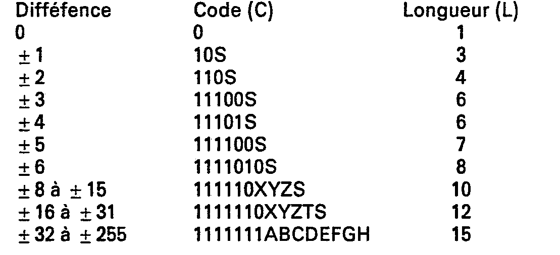
- the other fairly probable difference values, such as ⁇ 1, ⁇ 2, require only three or four bits. Larger difference values (such as the interval ⁇ 16 to ⁇ 31) require up to 12 bits but their probability of appearance is very low so that it has little effect on the compression rate obtained.
- the code words are arranged with an identification prefix and a suffix as well as (possibly) the sign bit S
- the identification prefix designates a given range of absolute difference values. For example, for the double interval of differences [ ⁇ 8 to ⁇ 15] we define a first prefix 111110, for the double interval of differences [ ⁇ 16 to ⁇ 31], we define a second prefix 1111110, and for the double interval of differences [ ⁇ 32 to ⁇ 255] a third prefix 1111111 is defined.
- the suffix XYZ has a sufficient number of bits (three) to represent all the absolute values of possible differences in the interval [ ⁇ 8 to ⁇ 15], since 3 bits allow 8 bit combinations. It is the same for the interval [ ⁇ 16 to ⁇ 31], whose suffix comprises 4 bits: XYZT.
- the fixed format word representing the pixel is directly transferred to the buffer memory 7 when the absolute value of the difference between this word and the previous one exceeds a chosen number.
- this number chosen is 31 so that for the double interval of differences [ ⁇ 32 to ⁇ 255], the suffix ABCDEFGH represents the very value of the pixel. Indeed, beyond 31, the coding of the difference would require more bits, taking into account the need to code the sign S, than the coding of the pixel itself (always positive).
- a third prefix of identification namely 1111111.
- the sign bit S is deleted during coding whenever possible.
- the conditions for suppressing the bit of sign S can apply in theory over the entire range of possible difference values (i.e. [-255 to +255] in the case described) but that, due to the particularity of direct coding of the pixel in the double interval [ ⁇ 32 to ⁇ 255], these conditions have meaning only for the interval complementary [-31 to +31] excluding zero.
- the examples which follow make it possible to understand the conditions for suppressing the bit of sign S.
- the inputs X n and X n-1 are directly connected to the inputs of a digital subtractor 20 including the parallel output D n (out of 9 bits) delivers the value of the difference at all times:
- TTL 181 the binary representation used in the subtractor is a two's complement representation
- a read only memory 21 PROM
- the absolute value appears coded on 8 bits, at a parallel output S 5 of the memory 21 and the sign bit appears at an output S 6 of the subtractor 20.
- the read only memory 21 is addressed directly by the output D ⁇ , it is that is to say that the parallel output D n of the subtractor 20 is connected to an address input of the read-only memory, each value of D n constituting an address of the memory 21 where the corresponding absolute value is found.
- the capacity of the memory 21 is reduced since it must contain 512 words of 8 bits.
- the programming of the latter is within the reach of those skilled in the art.
- the output S 5 and the input X n-1 are also connected to the two inputs (of the parallel type, 8 bits) of a digital adder 22 and to the two inputs of a digital subtractor 23, so as to carry out the two operations following:
- the output S 5 of the read only memory 21 is itself connected to the addressing input of a read only memory 29 in which the 256 possibilities for the length L and the value of the code C are written, without the sign S, denoted respectively L * and C * corresponding to the different possible values of the output S 5 .
- the code C * requires 11 bits and the length L * requires 4
- the read-only memory 29 will only require 3 boxes of the 82S115 type.
- Its addressing programming corresponds to the correspondence table described above, except for the double interval [ ⁇ 32 to ⁇ 255] and the sign bit S which does not appear.
- the outputs C "and L * are connected to corresponding inputs of a multiplexer 30 of the same type as the multiplexer 27.
- the outputs of the multiplexer 30 are connected to the inputs L 2 , C 2 of the multiplexer 27.
- the role of the multiplexer 30 is therefore to link either the group of inputs L 0 *, C 0 * or the group of inputs L 0 **, C o "to the corresponding inputs L 2 , C 2 .
- the control input e 6 of the multiplexer 30 is connected to the output of the gate 25 of the Exclusive OR type.
- the input L 0 ** is connected to the output L * of the read-only memory 29 via a binary operator 32 which performs the following operation: this incrementation therefore makes it possible to calculate the new length of the code when the sign S is reintroduced.
- the input C o is connected to the output C * of the memory 29 and includes an additional terminal connected to the output S 6 of the subtractor 20
- the control signal applied to the input e 6 therefore makes it possible to select the inputs L 0 *, C 0 * when the sign bit S can be deleted or the inputs L 0 ** C 0 ** when it must be
- a register 33 can be provided between the multiplexer 30 and the input C 2 of the multiplexer 27 to "format" the 15-bit code information, the register being controlled by the length information transmitted simultaneously to the input L 2 .
- circuit 2 which has just been described admits many variants. Among these, it is already advantageous, taking into account the capacities of the read-only memories proposed on the market, to replace the whole of this circuit by a single read-only memory (PROM) addressed directly by the values X n and X n-1 .
- PROM read-only memory
- block 2 can be a simple read only memory. If the inputs X n and X n-1 are each coded on 8 bits, which is comparable to a parallel addressing input of 16 bits for the read-only memory, there are therefore 65536 possible combinations which results in 64 K words of 15 bits for the code C and 64 K words of 4 bits for the code L.
- this read only memory is within the reach of those skilled in the art.
- the invention also relates to any compression method in which the results of the coding of the words L and C result only from a simple reading operation in a memory, as soon as the latter has been programmed by implementing the operations and tests defined above.
- Each point of the "tree" in FIG. 4 symbolizes a logic test between 0 and 1.
- 1. On the contrary, if the next bit is still 1, we progress again in the tree structure to be able to recognize
- 2 if the next bit is zero and so on ....
- the tree structure is limited by the use of tables (read only memories) containing all the possible combinations of the absolute values of differences included in the ranges [8 to 15], [16 to 31] and [32 to 255].
- the recognition of five consecutive 1s followed by a zero causes the addressing of the memory M 1 (corresponding to the first interval) by the following three bits.
- the recognition of six consecutive 1 followed by a zero causes the addressing of the memory M 2 (corresponding to the second interval) by the following four bits and the recognition of seven consecutive 1 causes the addressing of the memory M 3 (corresponding to the third interval) with the following eight bits.
- a circuit implementing the tree structure of FIG. 3 is easily produced from flip-flops and from said read-only memories M 1 , M 2 and M 3 . It can be seen that the succession of bits at the input E o thus conditions the recognition of the absolute value of the difference
Description
L'invention concerne un procédé de compression d'une succession d'informations numériques binaires, notamment représentatives des pixels d'une image numérisée ; l'invention a aussi pour objet un dispositif mettant en oeuvre un tel procédé.The invention relates to a method of compressing a succession of binary digital information, in particular representative of the pixels of a digitized image; the invention also relates to a device implementing such a method.
Dans un système numérique d'acquisition d'images, les valeurs des différentes zones élémentaires de l'image ou pixels sont transcrites en mots. La valeur de chaque mot représente la "luminance" du pixel considéré. Par exemple, dans le domaine de la radiologie numérique, l'image radiologique est visualisée par un amplificateur de luminance, captée par une caméra et le signal de cette caméra est échantillonné. La suite d'échantillons ainsi élaborée représente par exemple une lecture ligne par ligne par "balayage" des différents pixels de ces lignes. Cette suite d'échantillons est numérisée, c'est-à-dire transformée en une suite de mots. Si par exemple, chaque mot est codé sur 8 bits, ce qui représente une gradation de 0 à 255 du noir au blanc et si on se définit une image de 512 X 512 pixels, la capacité mémoire est importante, soit 2 097 152 bits à mémoriser. Lorsque de nombreuses images doivent être mémorisées, une mémoire de masse est indispensable. On utilise souvent un stockage sur disque magnétique. Généralement, une mémoire tampon de capacité limitée est couplée à la mémoire de masse, pour le transfert des informations. La mémoire de masse est donc "alimentée" par lectures successives des informations contenues dans la mémoire tampon. Les contraintes technologiques actuelles font que te transfert du contenu de la mémoire tampon vers la mémoire de masse est une opération qui demande du temps et qui limite les performances du système à un rythme d'images insuffisant dans certains cas, par exemple si on veut observer des phénomènes rapides comme l'évolution d'un produit de contraste dans le système sanguin ou le coeur. Il y a donc intérêt à comprimer les informations représentatives d'une image en exploitant les redondances spatiales et/ou temporelles inhérentes à celle-ci. Le taux de compression définit le gain réalisé après traitement. Ainsi, un taux de compression de 2 signifie qu'une mémoire tampon ayant la capacité nécessaire pour mémoriser une image normale complète, peut aussi accueillir les informations représentatives de deux images, après compression. Comme le temps de transfert entre la mémoire tampon et la mémoire de masse est invariable, cela revient à dire que le rythme d'acquisition des images peut être doublé.In a digital image acquisition system, the values of the various elementary areas of the image or pixels are transcribed into words. The value of each word represents the "luminance" of the pixel considered. For example, in the field of digital radiology, the radiological image is displayed by a luminance amplifier, captured by a camera and the signal from this camera is sampled. The series of samples thus produced represents for example a line by line reading by "scanning" of the different pixels of these lines. This series of samples is digitized, that is to say transformed into a series of words. If for example, each word is coded on 8 bits, which represents a gradation from 0 to 255 from black to white and if we define an image of 512 X 512 pixels, the memory capacity is significant, that is 2,097,152 bits at to memorize. When many images are to be stored, a mass memory is essential. We often use magnetic disk storage. Generally, a buffer memory of limited capacity is coupled to the mass memory, for the transfer of information. The mass memory is therefore "supplied" by successive readings of the information contained in the buffer memory. Current technological constraints mean that transferring the contents of the buffer memory to the mass memory is an operation which requires time and which limits the performance of the system to an insufficient rate of images in certain cases, for example if one wishes to observe rapid phenomena such as the development of a contrast medium in the blood system or the heart. It is therefore advantageous to compress the information representative of an image by exploiting the spatial and / or temporal redundancies inherent in it. The compression ratio defines the gain achieved after treatment. Thus, a compression ratio of 2 means that a buffer memory having the capacity necessary to memorize a complete normal image, can also receive the information representative of two images, after compression. As the transfer time between the buffer memory and the mass memory is invariable, this means that the rate of image acquisition can be doubled.
Une façon connue de comprimer une succession d'informations numériques résulte de la constatation que deux pixels voisins sont rarement très différents. Par conséquent, il est avantageux de mémoriser, non pas les pixels Xi, mais les différences Xi-Xi-,. En effet, si les pixels X; sont codés sur 8 bits, soit 256 valeurs possibles, la différence de deux pixels voisins sera dans la grande majorité des cas codable sur un nombre de bits inférieur à 5.A known way of compressing a succession of digital information results from the observation that two neighboring pixels are rarely very different. Consequently, it is advantageous to store, not the pixels X i , but the differences X i -X i- ,. Indeed, if the pixels X; are coded on 8 bits, ie 256 possible values, the difference of two neighboring pixels will in most cases be codable on a number of bits less than 5.
On connaît d'après le document "Nachrichtentechnische Zeitschrift, volume 27, N°3. Mars 1974, pages 115-118", un procédé de compression d'informations par suppression du bit de signe, mais ce procédé se fait avec perte d'informations et avec un code de longueur fixe.We know from the document "Nachrichtentechnische Zeitschrift,
Cependant, si on s'impose un codage sans perte d'information, il faut pouvoir aussi mémoriser les différences importantes entre pixels voisins, dont la probabilité d'apparition est faible mais qui se produisent néanmoins pour des détails aux transitions très contrastées. Pour résoudre ce problème, on a déjà proposé des codes à longueur variable, par exemple les codes de Huffman. Un tel code se traduit par un tableau de conversion où chaque valeur possible de différence (entre -255 et +255 pour l'exemple évoqué ci-dessus) reçoit un code binaire de longueur inversement proportionnelle à sa fréquence d'apparition. Ainsi, les valeurs de différence qui apparaissent le plus souvent au codage pendant l'exploration de l'image, pixel par pixel, reçoivent les codes les plus courts.However, if coding without loss of information is required, it is also necessary to be able to memorize the significant differences between neighboring pixels, whose probability of appearance is low but which nevertheless occur for details with very contrasted transitions. To solve this problem, variable length codes have already been proposed, for example the Huffman codes. Such a code results in a conversion table where each possible difference value (between -255 and +255 for the example mentioned above) receives a binary code of length inversely proportional to its frequency of appearance. Thus, the difference values which appear most often during coding during the exploration of the image, pixel by pixel, receive the shortest codes.
L'invention vise plusieurs perfectionnements de ce type de codage.The invention relates to several improvements to this type of coding.
En premier lieu, l'invention concerne donc un procédé de compression d'une succession d'informations numériques binaires sous perte d'informations se présentant sous la forme de mots de format fixe représentant des nombres entiers positifs de l'intervalle [0,N] consistant à soustraire chaque mot du précédent de façon à obtenir chaque fois une différence de format variable comportant un bit de signe, caractérisé en ce qu'il consiste, pour au moins certaines valeurs absolues de différences, à supprimer ledit bit de signe de ladite différence:
- - si la valeur absolue de celle-ci est supérieure à la valeur du mot précédent lorsque celui-ci est compris dans la première moitié dudit intervalle, ou,
- - si la valeur absolue de ladite différence est supérieure à la valeur de la différence entre le nombre N et la valeur du mot précédent lorsque celui-ci est compris dans la seconde moitié dudit intervalle, et
- - à transférer les informations ainsi comprimées, par exemple vers une mémoire.
- - if the absolute value of the latter is greater than the value of the preceding word when the latter is included in the first half of said interval, or,
- - if the absolute value of said difference is greater than the value of the difference between the number N and the value of the preceding word when the latter is included in the second half of said interval, and
- - Transfer the information thus compressed, for example to a memory.
Une autre caractéristique importante de l'invention consiste à coder directement la valeur du pixel dès que la différence dépasse, en valeur absolue, un nombre choisi. En effet, si on considère des pixels codés sur 8 bits, par exemple, une valeur de différence importante nécessite 9 bits pour être codée, en raison du signe de cette différence. Il devient alors avantageux de coder directement le pixel sur 8 bits, puisque c'est obligatoirement un nombre positif. Dans l'exemple qui sera décrit plus loin, on code directement le pixel (sur 8 bits) dès que la différence dépasse 31 en valeur absolue.Another important characteristic of the invention consists in directly coding the value of the pixel as soon as the difference exceeds, in absolute value, a chosen number. Indeed, if we consider pixels coded on 8 bits, for example, a large difference value requires 9 bits to be coded, because of the sign of this difference. It then becomes advantageous to code the pixel directly on 8 bits, since it is necessarily a positive number. In the example which will be described later, the pixel is directly coded (on 8 bits) as soon as the difference exceeds 31 in absolute value.
Enfin, une autre particularité notable de l'invention consiste à définir des intervalles donnés de différences possibles et à identifier chaque intervalle par un préfixe donné. Un suffixe comportant un nombre de bits suffisant pour représenter toutes les valeurs absolues de différences possibles dans l'intervalle considéré, suit directement le préfixe et un bit supplémentaire indique le signe. Ce mode d'identification des valeurs de différence a l'avantage de réduire "l'arborescence" des circuits électroniques de décodage, c'est-à-dire le nombre de tests logiques à effectuer avant de reconnaître complètement un mot. Ainsi, par exemple, la reconnaissance du préfixe pourra être exploitée pour adresser une table (mémoire morte) contenant directement toutes les valeurs possibles de différences dans l'intervalle correspondant au préfixe.Finally, another notable feature of the invention consists in defining given intervals of possible differences and in identifying each interval by a given prefix. A suffix with a sufficient number of bits to represent all the absolute values of possible differences in the interval considered, directly follows the prefix and an additional bit indicates the sign. This mode of identifying the values of The difference has the advantage of reducing the "tree structure" of the electronic decoding circuits, that is to say the number of logic tests to be carried out before fully recognizing a word. Thus, for example, the recognition of the prefix can be exploited to address a table (read-only memory) directly containing all the possible values of differences in the interval corresponding to the prefix.
L'invention concerne aussi un dispoitif de compression d'une succession d'informations numeriques binaires sous perte d'informations se presentant sous forme de mots de format fixe représentant des nombres entiers positifs de l'intervalle [0,N] comportant une entrée de mot où sont appliqués lesdits mots, un registre formant mémoire relié à ladite entrée pour mémoriser à chaque instant la valeur du mot précédant celui qui est appliqué à ladite entrée, et une mémoire pour recevoir une succession d'informations numériques de longueurs variables représentatives de la succession desdits mots de format fixe, caractérisé en ce qu'il comporte:
- des moyens pour transférer vers ladite mémoire tampon
- - soit la valeur absolue de la différence entre le mot appliqué à ladite entrée et ledit mot précédent si la valeur absolue de ladite différence est supérieure à la valeur du mot précédent lorsque celui-ci est compris dans la première moitié dudit intervalle ou si la valeur absolue de ladite différence est supérieure à la valeur de la différence entre le nombre N et la valeur du mot précédent lorsque celui-ci est compris dans la seconde moitié dudit intervalle,
- - soit la valeur de cette différence et de son signe dans le cas contraire.
- means for transferring to said buffer memory
- - either the absolute value of the difference between the word applied to said entry and said previous word if the absolute value of said difference is greater than the value of the previous word when the latter is included in the first half of said interval or if the value absolute of said difference is greater than the value of the difference between the number N and the value of the preceding word when the latter is included in the second half of said interval,
- - or the value of this difference and its sign otherwise.
L'invention sera mieux comprise et d'autres avantages de celle-ci apparaîtront mieux à la lumière de la description qui va suivre d'un mode de réalisation particulier d'un dispositif de compression conforme à son principe, donnée uniquement à titre d'exemple et faite en référence aux dessins annexés dans lesquels:
- - la figure 1 est un schéma bloc d'un dispositif de compression conforme à l'invention;
- - la figure 2 est un schéma de principe d'un séquenceur du dispositif de la figure 1;
- - la figure 3 est un schéma de principe d'un circuit de traitement de la figure 1 pour le codage des informations; et
- - la figure 4 illustre le principe du décodage.
- - Figure 1 is a block diagram of a compression device according to the invention;
- - Figure 2 is a block diagram of a sequencer of the device of Figure 1;
- - Figure 3 is a block diagram of a processing circuit of Figure 1 for coding information; and
- - Figure 4 illustrates the principle of decoding.
La figure 1 représente le schéma bloc d'un circuit de compression d'une succession de mots représentant les pixels d'une image. Les mots de 8 bits se présentent sous forme parallèle et sont appliqués à une entrée E pour subir une compression tandis que les informations numériques résultant de cette compression sont inscrits en série dans une mémoire tampon 7. Cette dernière est couplée à une mémoire de masse 8 (système à disque magnétique par exemple) et des lectures répétées de la mémoire tampon permettent "d'alimenter" la mémoire de masse B. Le but de la compression est d'augmenter la cadence d'acquisition des images malgré un rythme de transfert relativement lent entre les mémoires 7 et 8.FIG. 1 represents the block diagram of a circuit for compressing a succession of words representing the pixels of an image. The 8-bit words are in parallel form and are applied to an input E to undergo compression while the digital information resulting from this compression are written in series in a
Comme mentionné précédemment, le procédé de compression consiste pour l'essentiel à mémoriser, non les mots de 8 bits représentant les pixels mais la différence entre deux pixels successifs, en utilisant un code de longueur variable. L'entrée E est donc reliée à une entrée Xn d'un circuit de traitement 2 qui sera décrit plus loin et à un registre 1 formant mémoire dont la sortie est reliée à une entrée Xn-1 du circuit de traitement 2. Ce dernier reçoit donc à tout moment sur ses deux entrées la valeur d'un pixel et celle du pixel précédent. Les entrées E, Xn, Xn-1 sont des entrées parallèles de 8 bits (c'est-à-dire présentant chacune 8 bornes d'accès) et le registre 1 est à entrée parallèle et sortie parallèle, également sur 8 bits. Sur les dessins, chaque liaison parallèle est conventionnellement représentée par un seul fil coupé par un trait oblique auprès duquel figure le nombre de bits de ladite liaison. Le circuit 2 comporte une sortie parallèle C (de 16 bits) délivrant l'information (le code) à enregistrer, codée et "formatée", ainsi qu'une sortie parallèle L (de 4 bits) délivrant une information représentative de la longueur du code apparaissant simultanément à la sortie C. La sortie L est appliquée à une entrée d'un séquenceur 4 comportant 3 sorties d'horloge S1, S2 et S3 connectées respectivement pour piloter trois registres de 8 bits, 3, 5 et 6. L'agencement du séquenceur 4 sera décrit plus loin. La sortie C du circuit de traitement 2 est reliée à l'entrée du registre 3 qui est du type à chargement parallèle et sortie série. Le séquenceur décode la longueur utile du code C "formatée" à 16 bits, à transférer en série vers le registre 5 ou le registre 6. Plus précisément, la sortie S1 délivre chaque fois un nombre d'impulsions égal à la longueur L et ce signal d'horloge appliqué au registre 3 pilote le transfert des bits de poids fort correspondants vers le registre 5 ou 6 qui se trouve validé par l'horloge S2 ou S3 correspondante.As mentioned previously, the compression method essentially consists in memorizing, not the 8-bit words representing the pixels but the difference between two successive pixels, using a variable length code. The input E is therefore connected to an input Xn of a
Par exemple, si le mot représentatif d'une différence Xn-Xn-1 est égal à +2, ce qui peut se transcrire en code comprimé binaire:
- 1100 avec L = 4
- le code C "formaté" à 16 bits sera
- 0000000000001100
- 1100 with L = 4
- 16-bit "formatted" C code will be
- 0000000000001100
Mais la sortie L programme le séquenceur pour que celui-ci ne génère que 4 impulsions d'horloge à la sortie S1 de sorte que seul le mot 1100 s'inscrit dans l'un des registres 5 ou 6. Le format adopté de 16 bits, pour le code C correspond à la longueur maximum des mots à transférer dans la mémoire 7.But the output L programs the sequencer so that it generates only 4 clock pulses at the output S1 so that only the word 1100 is written in one of the
La sortie série S4 du registre 3 est reliée aux entrées E1 et E2 des registres 5 et 6, respectivement. Ces registres sont du type entrée série - sortie parallèle. Les deux sorties S5, S6 de ces registres sont reliées à une entree parallèle E3 de la mémoire 7 qui comporte en outre une entrée d'adressage Ad pilotée par le séquenceur 4. La présence des deux registres 5 et 6 se justifie par le fait que la mémoire 7 est classiquement agencée en mots adressables de 8 bits. Ainsi, les horloges disponibles aux sorties 52 et 53 valident alternativement les registres 5 et 6. Chaque fois qu'un registre 5 (ou 6) a reçu 8 bits en provenance du registre 3, le séquenceur commute la suite du déchargement du registre 3 vers l'autre registre 6 (ou 5). Dans le même temps il génère l'adresse de la mémoire 7 à laquelle doit être déchargé le registre 5 (ou 6).The serial output S4 of
Le séquenceur est représenté à la figure 2. Il comporte un générateur d'horloge H qui pilote un décompteur 9 à entrée de consigne parallèle, connectée à la sortie L du circuit 2 et recevant par conséquent un mot représentatif de la longueur du code. Le générateur d'horloge N est également relie a une entrée d'une porte ET, 10 à deux entrées dont la sortie constitue la sortie S1 pilotant le registre 3. Le décompteur 9 comporte une sortie S9 dite "d'état zéro" qui change d'état lorsque l'horloge H a remis le décompteur à zéro, c'est-à-dire lorsqu'elle a délivré un nombre d'impulsions correspondant à la longueur L affichée à l'entrée de consigne. Cette sortie S9 est connectée à l'autre entrée de la porte 10. Son changement d'état bloque la porte 10 et interrompt donc la transmission des impulsions d'horloge à la sortie Si. La sortie de la porte ET, 10 est aussi reliée à l'entrée d'un compteur Il. Il s'agit d'un compteur par huit qui pilote une bascule bistable 12 et un compteur d'adresses 13. La sortie de ce dernier constitue la sortie Ad qui pilote la mémoire 7. La sortie Q de la bascule 12 est reliée à une entrée d'une porte ET, 14, à deux entrées tandis que sa sortie Q est reliée à une entrée d'une porte ET, 15, à deux entrées. Les deux autres entrées des portes 14 et 15 sont connectées à la sortie Sl. Les sorties des portes 14 et 15 constituent les sorties S2 et S3 mentionnées ci-dessus. Ainsi, chaque fois que le compteur 11 a enregistré 8 impulsions d'horloge H transmises par la porte 10, il pilote le changement d'état de la bascule 12, ce qui inverse la validation des registres 5 et 6 pour le chargement des informations délivrées par le compteur 3. Dans le même temps, le compteur 11 incrémente le compteur d'adresses 13 d'une unité, pour le transfert des informations contenues dans le registre qui vient d'être "rempli" à une nouvelle adresse de la mémoire 7.The sequencer is shown in FIG. 2. It includes a clock generator H which drives a down-
Avant d'aborder la description du circuit de traitement 2 qui effectue l'essentiel des opérations de compression des informations représentatives des pixels Xi, il faut expliciter le processus de codage choisi. Soit Dn, la différence entre deux pixels consécutifs:![]()
![]()
On vérifie que Dn = 0, c'est-à-dire la valeur de différence statistiquement la plus fréquente dans la succession des pixels de l'image, est codée avec le mot de longueur minimum, c'est-à-dire sur un bit. Les autres valeurs de différences assez probables, comme par exemple ± 1, ± 2, ne nécessitent que trois ou quatre bits. Les valeurs de différences plus importantes (comme par exemple l'intervalle ±16 à ±31) nécessitent jusqu'à 12 bits mais leur probabilité d'apparition est très faible de sorte que cela joue peu sur le taux de compression obtenu. Dans le code, le dernier bit 5 représente le signe. Par exemple, S = 0 si la différence Dn est positive et S = 1 si Dn est négative. Comme on le verra plus loin, le bit de signe peut dans certains cas être supprimé.It is verified that D n = 0, that is to say the most frequent statistically difference value in the succession of the pixels of the image, is coded with the word of minimum length, that is to say on a bit. The other fairly probable difference values, such as ± 1, ± 2, require only three or four bits. Larger difference values (such as the interval ± 16 to ± 31) require up to 12 bits but their probability of appearance is very low so that it has little effect on the compression rate obtained. In the code, the
Par ailleurs, selon un aspect avantageux de l'invention et à partir d'une valeur absolue de différence supérieure à 7, les mots de code sont agencés avec un préfixe d'identification et un suffixe ainsi que (éventuellement) le bit de signe S. Le préfixe d'identification désigne un intervalle donné de valeurs absolues de différences. Par exemple, pour l'intervalle double de différences [ ± 8 à ± 15] on définit un premier préfixe 111110, pour l'intervalle double de différences [±16 à ±31], on définit un second préfixe 1111110, et pour l'intervalle double de différences [±32 à ±255] on définit un troisième préfixe 1111111. On notera que le suffixe XYZ comporte un nombre de bits suffisant (trois) pour représenter toutes les valeurs absolues de différences possibles dans l'intervalle [± 8 à ± 15], puisque 3 bits permettent 8 combinaisons binaires. Il en est de même pour l'intervalle [ ± 16 à ± 31], dont le suffixe comporte 4 bits : XYZT.Furthermore, according to an advantageous aspect of the invention and from an absolute value of difference greater than 7, the code words are arranged with an identification prefix and a suffix as well as (possibly) the sign bit S The identification prefix designates a given range of absolute difference values. For example, for the double interval of differences [± 8 to ± 15] we define a first prefix 111110, for the double interval of differences [± 16 to ± 31], we define a second prefix 1111110, and for the double interval of differences [± 32 to ± 255] a
En revanche, selon une particularité avantageuse de l'invention, on transfère directement le mot de format fixe représentant le pixel vers la mémoire tampon 7 lorsque la valeur absolue de la différence entre ce mot et le précédent dépasse un nombre choisi. Selon l'exemple, ce nombre choisi est 31 de sorte que pour l'intervalle double de différences [±32 à ±255], le suffixe ABCDEFGH représente la valeur même du pixel. En effet, au-delà de 31, le codage de la différence nécessiterait plus de bits, compte tenu de la nécessité de coder le signe S, que le codage du pixel lui-même (toujours positif). On associe à ce suffixe, un troisième préfixe d'identification, à savoir 1111111.On the other hand, according to an advantageous feature of the invention, the fixed format word representing the pixel is directly transferred to the
Selon une caractéristique importante de l'invention, le bit de signe S est supprimé au codage chaque fois que c'est possible. Il est à noter que les conditions de suppression du bit de signe S, telles qu'elles vont être exposées ci-dessous, peuvent s'appliquer en théorie sur tout l'intervalle des valeurs de différences possibles (c'est-à-dire [-255 à +255] dans le cas décrit) mais que, en raison de la particularité de codage direct du pixel dans l'intervalle double [±32 à ±255], ces conditions n'ont de sens que pour l'intervalle complémentaire [-31 à +31] non compris le zéro. Les exemples qui suivent permettent de comprendre les conditions de suppression du bit de signe S.According to an important characteristic of the invention, the sign bit S is deleted during coding whenever possible. It should be noted that the conditions for suppressing the bit of sign S, as they will be explained below, can apply in theory over the entire range of possible difference values (i.e. [-255 to +255] in the case described) but that, due to the particularity of direct coding of the pixel in the double interval [± 32 to ± 255], these conditions have meaning only for the interval complementary [-31 to +31] excluding zero. The examples which follow make it possible to understand the conditions for suppressing the bit of sign S.
On a toujours 0 ≤ Xi ≤ N, selon l'exemple 0 ≤ Xi ≤ 255
- a) supposons Xn-1 = 0, quelle que soit la valeur du pixel suivant Xn, la différence: Dn = Xn-Xn-1 est forcément positive. On peut donc supprimer le signe S de Dn dans tous les cas.
- b) supposons Xn-1 = 1, la seule différence négative possible est -1, il faut alors coder ± 1 sur 3 bits en conservant le bit de signe. Pour toutes les autres valeurs de différences, Dn peut être amputé du bit de signe S.
- c) supposons Xn-1 = 2, les seules différences négatives possibles sont -1 et -2. Pour lever l'indétermination, il faut donc coder ± 1 et ± 2 en conservant le bit de signe S. Pour toutes les autres valeurs de différences Dn peut être amputé du bit de signe S.
- a) suppose X n-1 = 0, whatever the value of the next pixel X n , the difference: D n = X n -X n-1 is necessarily positive. We can therefore remove the sign S from D n in all cases.
- b) suppose X n-1 = 1, the only possible negative difference is -1, we must then code ± 1 on 3 bits while keeping the sign bit. For all other difference values, D n can be cut off by the bit of sign S.
- c) suppose X n-1 = 2, the only possible negative differences are -1 and -2. To remove the indeterminacy, it is therefore necessary to code ± 1 and ± 2 while keeping the sign bit S. For all other difference values D n can be reduced by the sign bit S.
On peut continuer ce raisonnement pour toutes les valeurs de l'avant dernier pixel Xn-1, comprises dans la première moitié de l'intervalle de variation des pixels Xi. Autrement dit, on supprime le bit de signe S si la valeur absolue de la différence Dn est supérieure à l'avant dernier mot lorsque celui-ci est compris dans la première moitié de l'intervalle des X; En fait, pour la raison indiquée précédemment, ce genre de test sera arrêté lorsque la valeur absolue de la différence sera supérieure à 31.
- d) supposons maintenant Xn-1 = N = 255. Quelle que soit la valeur du pixel suivant Xn, la différence Dn = Xn-Xn-1 est forcément négative. On peut donc aussi supprimer le signe S de Dn dans tous les cas.
- e) supposons Xn-1 = 254, la seule différence positive possible est + 1 si Xn = 255. Pour lever l'indétermination on code les différences Dn = ± 1 sur 3 bits en conservant le bit de signe. Pour toutes les autres valeurs de différences, Dn peut être amputé du bit de signe S.
- f) supposons Xn-1 = 253, les seules différences positives possibles sont + 1 et +2, correspondant à Xn = 254 ou Xn = 255. On code alors les différences ± 1 et ± 2 en conservant le bit de signe S. Pour toutes les autres valeurs de différences, Dn peut être amputé du bit de signe S.
- d) now suppose X n-1 = N = 255. Whatever the value of the next pixel X n , the difference D n = X n -X n-1 is necessarily negative. We can therefore also remove the sign S from D n in all cases.
- e) suppose X n-1 = 254, the only possible positive difference is + 1 if X n = 255. To remove the indeterminacy, we code the differences D n = ± 1 in 3 bits while keeping the sign bit. For all other difference values, D n can be cut off by the bit of sign S.
- f) suppose X n-1 = 253, the only possible positive differences are + 1 and +2, corresponding to X n = 254 or X n = 255. We then code the differences ± 1 and ± 2 while keeping the sign bit S. For all other difference values, D n can be cut off by the bit with sign S.
On peut continuer ce raisonnement pour toutes les valeurs de l'avant dernier pixel Xn-1 comprises dans la seconde moitié de l'intervalle de variation des pixels Xi. Autrement dit, on supprime le bit de signe S si la valeur absolue de la différence Dn est supérieure à la valeur de la différence entre le nombre N (N = 255) et la valeur de l'avant dernier pixel Xn-1, lorsque celui-ci est compris dans la seconde moitié de l'intervalle de variation des pixels Xi. Là encore, cependant, ce genre de test est abandonné lorsque la valeur absolue de la différence devient supérieure à 31.We can continue this reasoning for all the values of the penultimate pixel X n-1 included in the second half of the interval of variation of the pixels X i . In other words, the sign bit S is deleted if the absolute value of the difference D n is greater than the value of the difference between the number N (N = 255) and the value of the penultimate pixel X n-1 , when the latter is included in the second half of the pixel variation interval X i . Again, however, this kind of test is abandoned when the absolute value of the difference becomes greater than 31.
On va maintenant décrire en référence à la figure 3 un mode de réalisation possible du circuit de traitement 2. Les entrées Xn et Xn-1 sont directement reliées aux entrées d'un soustracteur numérique 20 dont la sortie parallèle Dn (sur 9 bits) délivre à chaque instant la valeur de la différence:![]()
![]()
On peut par exemple utiliser un circuit intégré du commerce de type ALU 4 bits (TTL 181) proposé par les principaux constructeurs de semi-conducteurs. Comme la représentation binaire utilisée dans le soustracteur est une représentation en complément à deux, on utilise une mémoire morte 21 (PROM) pour extraire la valeur absolue de la différence. La valeur absolue apparaît codée sur 8 bits, à une sortie S5 parallèle de la mémoire 21 et le bit de signe apparaît à une sortie S6 du soustracteur 20. La mémoire morte 21 est adressée directement par la sortie Dµ, c'est-à-dire que la sortie parallèle Dn du soustracteur 20 est reliée à une entrée d'adressage de la mémoire morte, chaque valeur de Dn constituant une adresse de la mémoire 21 où se trouve inscrite la valeur absolue correspondante. La capacité de la mémoire 21 est réduite puisqu'elle doit contenir 512 mots de 8 bits. On peut par exemple utiliser un circuit intégré du type 82S115 proposé par les principaux constructeurs de semi-conducteurs; un seul boîtier suffit pour réaliser la mémoire 21. La programmation de cette dernière est à la portée de l'homme du métier.One can for example use a commercial integrated circuit of the 4-bit ALU type (TTL 181) offered by the main semiconductor manufacturers. As the binary representation used in the subtractor is a two's complement representation, a read only memory 21 (PROM) is used to extract the absolute value of the difference. The absolute value appears coded on 8 bits, at a parallel output S 5 of the
La sortie S5 et l'entrée Xn-1 sont également rellées aux deux entrées (de type parallele, 8 bits) d'un additionneur numérique 22 et aux deux entrées d'un soustracteur numérique 23, de façon à réaliser les deux opérations suivantes:![]()
![]()
![]()
![]()
Les circuits 22 et 23 peuvent être réalisés à partir du même type de circuit intégré que le soustracteur 20. La sortie "report" Sa de l'additionneur 22 et la sortie "report" S9 du soustracteur 23 sont reliées respectivement aux deux entrées d'une porte 25 du type OU Exclusif. Autrement dit, la sortie S8 affiche la valeur du bit de report de l'opération Xn-1 +|Dn| tandis que la sortie S9 affiche la valeur du bit de report de l'opération Xn-1 -|Dn|. L'ensemble (22, 23, 25) qui vient d'être décrit réalise de façon simple l'ensemble des tests (définis ci-dessus) permettant de déterminer si le bit de signe peut être supprimé ou non. On vérifie en effet que si les deux valeurs:
- Xn-1 +|Dn| et Xn-1 -|Dn| sont dans l'intervalle [0,N], cela signifie qu'il faut tenir compte du signe dans la transmission du code C vers la mémoire tampon. Si au contraire une valeur se trouver à l'extérieur de l'intervalle [0,N], cela signifie qu'on peut supprimer le bit de signe. Or, ces conditions s'expriment par la table de la vérité de la
porte 25, puisque, si la sortie de cette porte est à 1, cela signifie que l'un seulement des bits de report a la valeur 1, c'est-à-dire que le résultat de l'une seulement des opérations est en dehors de l'intervalle [0,N].
- X n-1 + | D n | and X n-1 - | D n | are in the interval [0, N], this means that the sign must be taken into account when transmitting the code C to the buffer memory. If, on the contrary, a value is outside the interval [0, N], this means that the sign bit can be deleted. However, these conditions are expressed by the truth table of
gate 25, since, if the output of this gate is at 1, it means that only one of the carry bits has thevalue 1, that is that is, the result of only one of the operations is outside the range [0, N].
Par ailleurs, la sortie Ss est reliée à un comparateur 26 qui permet de déterminer si la valeur absolue de la différence Dn est supérieure ou inférieure à 31. Pratiquement, ce comparateur peut être une simple porte OU à trois entrées auxquelles on relie les trois dernières bornes de la sortie S5 (sur lesquelles apparaissent les bits de poids fort). Comme le nombre 31 s'exprime par:
- 00011111 en binaire,
un nombre supérieur aura forcément au moins l'un de ses trois bits de poids forts égal à 1. La sortie de cette porte est reliée à une entrée de pilotage e5 d'un multiplexeur 27 dont les sorties L et C sont les sorties représentées à la figure 2. Ce multiplexeur comporte deux groupes d'entrées L1' C1 et L2, C2, respectivement, et son rôle consiste simplement à faire correspondre les entrées Ll, C1 ou L2, C2 avec les sorties L, C en fonction de la commande appliquée à l'entrée e5. L'entrée L1 est fixe et exprime le nombre 15 en binaire, les 8 bornes correspondant aux bits de poids faibles de l'entrée C1 reçoivent directement le mot Xn tandis que les 7 bornes correspondant aux bits de poids forts de cette même entrée C1 sont toutes à 1. Ainsi se trouve simplement réalisée la double transcription Longueur, Code, dans le cas ou la valeur de la différence appartient à l'intervalle double [±32 à ±255] identifié par le comparateur 26. Le multiplexeur 27 peut par exemple être réalisé à partir d'un circuit intégré du type 74244.Furthermore, the output S s is connected to a
- 00011111 in binary,
a higher number will necessarily have at least one of its three most significant bits equal to 1. The output of this gate is connected to a control input e5 of a
La sortie S5 de la mémoire morte 21 est elle-même reliée à l'entrée d'adressage d'une mémoire morte 29 dans laquelle sont inscrites les 256 possibilités pour la longueur L et la valeur du code C, sans le signe S, notées respectivement L* et C* correspondant aux différentes valeurs possibles de la sortie S5. Comme le code C* nécessite 11 bits et la longueur L* en nécessite 4, la mémoire morte 29 ne nécessitera que 3 boîtiers de type 82S115. Sa programmation d'adressage correspond au tableau de correspondance décrit ci-dessus, sauf en ce qui concerne l'intervalle double [ ± 32 à ± 255] et le bit de signe S qui n'apparaît pas. Les sorties C" et L* sont reliées à des entrées correspondantes d'un multiplexeur 30 du même type que le multiplexeur 27. Les sorties du multiplexeur 30 sont reliées aux entrées L2, C2 du multiplexeur 27. Le rôle du multiplexeur 30 est donc de relier soit le groupe d'entrées L0*, C0* soit le groupe d'entrées L0**, Co" aux entrées correspondantes L2, C2. L'entrée de pilotage e6 du multiplexeur 30 est reliée à la sortie de la porte 25 de type OU Exclusif. L'entrée L0** est reliée à la sortie L* de la mémoire morte 29 par l'intermédiaire d'un opérateur binaire 32 qui réalise l'opération suivante:![]()
![]()
Le fonctionnement du circuit de traitement de la figure 3 résulte avec évidence de sa description. On voit que pour tout couple de pixels Xn, Xn-1' on effectue systématiquement la différence Dn (soustracteur 20) puis on classe la valeur absolue de Dn par rapport audit "nombre choisi", c'est-à-dire 31, grâce au comparateur 26. Cette classification permet de positionner le multiplexeur 27, c'est-à-dire de transmettre éventuellement le mot Xn et sa longueur vers les sorties L et C du multiplexeur 27 si |Dn|>31. Dans le cas contraire, on supprime le signe de la différence lorsque c'est possible, ce qui se traduit par le positionnement du multiplexeur 30 sous le contrôle de la porte 25. Si le signe peut être supprimé, les sorties L* C* de la mémoire 29 deviennent les sorties L, C du système. Dans le cas contraire, on les complète pour réintroduire le signe disponible à la sortie S6.The operation of the processing circuit of Figure 3 is evident from its description. We see that for any pair of pixels X n , X n-1 ' we systematically make the difference D n (subtractor 20) and then classify the absolute value of D n with respect to said "chosen number", that is to say say 31, thanks to the
Bien entendu, le circuit 2 qui vient d'être décrit, admet de nombreuses variantes. Parmi celles-ci, il est d'ores et déjà avantageux, compte tenu des capacités des mémoires mortes proposées dans le commerce, de remplacer l'ensemble de ce circuit par une unique mémoire morte (PROM) adressée directement par les valeurs Xn et Xn-1. Autrement dit, en se reportant à nouveau à la figure 1, le bloc 2 peut être une simple mémoire morte. Si les entrées Xn et Xn-1 sont codées chacune sur 8 bits, ce qui est assimilable à une entrée d'adressage parallèle de 16 bits pour la mémoire morte, on a donc 65536 combinaisons possibles ce qui se traduit par 64 K mots de 15 bits pour le code C et 64 K mots de 4 bits pour le code L. Si on utilise par exemple des circuits intégrés du type 27128, qui ont chacun une capacité mémoire de 16 K octets, il suffira de huit boîtiers pour enregistrer une fois pour toutes les 64 K valeurs possibles du code C et de quatre boîtiers pour enregistrer les 64 K valeurs possibles de la longueur L, soit un total de douze boîtiers seulement.Of course, the
La programmation de cette mémoire morte est à la portée de l'homme du métier. On pourra par exemple simuler le système de la figure 3 sur ordinateur en générant successivement toutes les valeurs possibles pour Xn et Xn-1. On peut aussi construire le système de la figure 3 pour l'utiliser en tant que programmateur des boîtiers.The programming of this read only memory is within the reach of those skilled in the art. We can for example simulate the system of figure 3 on computer by successively generating all the possible values for X n and X n-1 . We can also build the system of figure 3 to use it as a programmer housings.
Par conséquent, l'invention vise aussi tout procédé de compression dans lequel les résultats du codage des mots L et C ne résultent que d'une simple opération de lecture dans une mémoire, dès lors que cette dernière a été programmée en mettant en oeuvre les opérations et tests définis ci-dessus.Consequently, the invention also relates to any compression method in which the results of the coding of the words L and C result only from a simple reading operation in a memory, as soon as the latter has been programmed by implementing the operations and tests defined above.
Le décodage va maintenant être brièvement explicité. Chaque point de "l'arborescence" de la figure 4 symbolise un test logique entre 0 et 1. La suite des bits représentant les informations après compression est appliquée à l'entrée Eo, le premier pixel ayant été codé en tant que tel. Par conséquent, si le bit suivant est zéro, on l'interprète comme D, = 0. L'arrivée d'un 1 implique en revanche un test supplémentaire. Si le bit suivant est un zero, on aboutit à |Dn| = 1. Au contraire, si le bit suivant est encore 1 on progresse à nouveau dans l'arborescence pour pouvoir reconnaître |Dn| = 2 si le bit suivant est zéro et ainsi de suite.... Au delà de IDnl = 7, l'arborescence est limitée grâce à l'emploi de tables (mémoires mortes) contenant toutes les combinaisons possibles des valeurs absolues de différences comprises dans les intervalles [8 à 15], [16 à 31 ] et [32 à 255]. Ainsi, la reconnaissance de cinq 1 consécutifs suivis d'un zéro provoque l'adressage de la mémoire M1 (correspondant au premier intervalle) par les trois bits suivants. La reconnaissance de six 1 consécutifs suivis d'un zéro provoque l'adressage de la mémoire M2 (correspondant au second intervalle) par les quatre bits suivants et la reconnaissance de sept 1 consécutifs provoque l'adressage de la mémoire M3 (correspondant au troisième intervalle) par les huit bits suivants.Decoding will now be briefly explained. Each point of the "tree" in FIG. 4 symbolizes a logic test between 0 and 1. The series of bits representing the information after compression is applied to the input E o , the first pixel having been coded as such. Consequently, if the next bit is zero, it is interpreted as D, = 0. The arrival of a 1, on the other hand, involves an additional test. If the next bit is a zero, we arrive at | D n | = 1. On the contrary, if the next bit is still 1, we progress again in the tree structure to be able to recognize | D n | = 2 if the next bit is zero and so on .... Beyond ID nl = 7, the tree structure is limited by the use of tables (read only memories) containing all the possible combinations of the absolute values of differences included in the ranges [8 to 15], [16 to 31] and [32 to 255]. Thus, the recognition of five consecutive 1s followed by a zero causes the addressing of the memory M 1 (corresponding to the first interval) by the following three bits. The recognition of six consecutive 1 followed by a zero causes the addressing of the memory M 2 (corresponding to the second interval) by the following four bits and the recognition of seven consecutive 1 causes the addressing of the memory M 3 (corresponding to the third interval) with the following eight bits.
Un circuit mettant en oeuvre l'arborescence de la figure 3 est aisément réalisable à partir de bascules bistables et desdites mémoires mortes M1, M2 et M3. On conçoit que la succession des bits à l'entrée Eo conditionne ainsi la reconnaissance de la valeur absolue de la différence |Dn|.A circuit implementing the tree structure of FIG. 3 is easily produced from flip-flops and from said read-only memories M 1 , M 2 and M 3 . It can be seen that the succession of bits at the input E o thus conditions the recognition of the absolute value of the difference | D n |.
Si on mémorise la valeur du pixel précédent, il est facile de refaire les opérations:![]()
![]()
![]()
![]()
Claims (14)
Applications Claiming Priority (2)
| Application Number | Priority Date | Filing Date | Title |
|---|---|---|---|
| FR8318132 | 1983-11-15 | ||
| FR8318132A FR2554995B1 (en) | 1983-11-15 | 1983-11-15 | METHOD FOR COMPRESSING A SUCCESSION OF DIGITAL INFORMATION AND DEVICE USING THE SAME |
Publications (3)
| Publication Number | Publication Date |
|---|---|
| EP0142439A2 EP0142439A2 (en) | 1985-05-22 |
| EP0142439A3 EP0142439A3 (en) | 1985-06-19 |
| EP0142439B1 true EP0142439B1 (en) | 1988-07-20 |
Family
ID=9294125
Family Applications (1)
| Application Number | Title | Priority Date | Filing Date |
|---|---|---|---|
| EP84402265A Expired EP0142439B1 (en) | 1983-11-15 | 1984-11-09 | Method of compressing a train of digital information, and apparatus therefor |
Country Status (4)
| Country | Link |
|---|---|
| US (1) | US4646148A (en) |
| EP (1) | EP0142439B1 (en) |
| DE (1) | DE3472844D1 (en) |
| FR (1) | FR2554995B1 (en) |
Families Citing this family (25)
| Publication number | Priority date | Publication date | Assignee | Title |
|---|---|---|---|---|
| US5051991A (en) * | 1984-10-17 | 1991-09-24 | Ericsson Ge Mobile Communications Inc. | Method and apparatus for efficient digital time delay compensation in compressed bandwidth signal processing |
| FR2591050B1 (en) * | 1985-12-04 | 1990-07-20 | Thomson Cgr | METHOD AND DEVICE FOR CONDITIONALLY ENCODING COMPRESSION OF DIGITAL IMAGES WITHOUT LOSS OF INFORMATION |
| FR2600223B1 (en) * | 1986-01-13 | 1988-08-19 | Thomson Cgr | METHOD OF FORMATTING AND DEFORMATTING DATA RESULTING FROM CODING OF DIGITAL INFORMATION USING A VARIABLE LENGTH CODE, AND IMPLEMENTING DEVICE |
| US4799242A (en) * | 1987-08-24 | 1989-01-17 | International Business Machines Corporation | Multi-mode dynamic code assignment for data compression |
| US5051904A (en) * | 1988-03-24 | 1991-09-24 | Olganix Corporation | Computerized dynamic tomography system |
| CA1315392C (en) * | 1988-11-18 | 1993-03-30 | Taejeong Kim | Side-match and overlap-match vector quantizers for images |
| GB2226470A (en) * | 1988-12-23 | 1990-06-27 | Philips Electronic Associated | Encoding,decoding and processing pixel values for storing and reproducing a digitised image in expanded format |
| US5237316A (en) * | 1990-02-02 | 1993-08-17 | Washington University | Video display with high speed reconstruction and display of compressed images at increased pixel intensity range and retrofit kit for same |
| US5796872A (en) * | 1992-03-25 | 1998-08-18 | Canon Kabushiki Kaisha | Method and apparatus for compressing and decompressing image data |
| US5448642A (en) * | 1992-05-12 | 1995-09-05 | The United States Of America As Represented By The Administrator Of The National Aeronautics And Space Administration | Method for coding low entrophy data |
| FR2705223A1 (en) * | 1993-05-13 | 1994-11-25 | Ge Medical Syst Sa | Method for acquiring images of a body by rotational placement |
| US5903671A (en) * | 1993-12-27 | 1999-05-11 | Canon Kabushiki Kaisha | Data compression method and apparatus therefor |
| US5550541A (en) * | 1994-04-01 | 1996-08-27 | Dolby Laboratories Licensing Corporation | Compact source coding tables for encoder/decoder system |
| FR2718875B1 (en) * | 1994-04-15 | 1996-05-15 | Sextant Avionique | Landing assistance device. |
| JPH08204577A (en) * | 1995-01-26 | 1996-08-09 | Sega Enterp Ltd | Method and device for data encoding and those for decoding |
| US6101276A (en) * | 1996-06-21 | 2000-08-08 | Compaq Computer Corporation | Method and apparatus for performing two pass quality video compression through pipelining and buffer management |
| JP3339335B2 (en) * | 1996-12-12 | 2002-10-28 | ヤマハ株式会社 | Compression encoding / decoding method |
| US6549652B1 (en) | 1998-09-11 | 2003-04-15 | Cirrus Logic, Inc. | Method and apparatus for reducing noise during lossy transformation processes |
| US7158681B2 (en) * | 1998-10-01 | 2007-01-02 | Cirrus Logic, Inc. | Feedback scheme for video compression system |
| US6307971B1 (en) | 1998-10-01 | 2001-10-23 | Sharewave, Inc. | Method and apparatus for digital data compression |
| US7212676B2 (en) * | 2002-12-30 | 2007-05-01 | Intel Corporation | Match MSB digital image compression |
| KR20080016881A (en) * | 2005-05-24 | 2008-02-22 | 코닌클리케 필립스 일렉트로닉스 엔.브이. | Compression and decompression using corrections of predicted values |
| US7536057B2 (en) * | 2005-10-31 | 2009-05-19 | Northrop Grumman Corporation | Open system architecture for surveillance systems with efficient bandwidth management |
| US9742434B1 (en) * | 2016-12-23 | 2017-08-22 | Mediatek Inc. | Data compression and de-compression method and data compressor and data de-compressor |
| US10706492B2 (en) * | 2017-09-05 | 2020-07-07 | Texas Instruments Incorporated | Image compression/decompression in a computer vision system |
Family Cites Families (9)
| Publication number | Priority date | Publication date | Assignee | Title |
|---|---|---|---|---|
| US3474442A (en) * | 1966-10-03 | 1969-10-21 | Xerox Corp | Format generator circuit |
| US3723879A (en) * | 1971-12-30 | 1973-03-27 | Communications Satellite Corp | Digital differential pulse code modem |
| DE2405534C2 (en) * | 1974-02-06 | 1983-06-01 | AEG-Telefunken Nachrichtentechnik GmbH, 7150 Backnang | Message transmission system, in particular for the transmission of video signals |
| FR2314618A1 (en) * | 1975-06-13 | 1977-01-07 | Thomson Csf | Data transmission using differential pulse code modulation - has variable code length for digital data relating to amplitude variations |
| JPS5255313A (en) * | 1975-10-30 | 1977-05-06 | Kokusai Denshin Denwa Co Ltd | Facsimile signal coding system |
| JPS5816665B2 (en) * | 1975-10-30 | 1983-04-01 | ケイディディ株式会社 | Fuakushimirishingounofugoukahoushiki |
| JPS6043703B2 (en) * | 1976-02-27 | 1985-09-30 | 富士ゼロックス株式会社 | Binary signal facsimile data compression method |
| GB2050752B (en) * | 1979-06-07 | 1984-05-31 | Japan Broadcasting Corp | Motion compensated interframe coding system |
| US4325085A (en) * | 1980-06-09 | 1982-04-13 | Digital Communications Corporation | Method and apparatus for adaptive facsimile compression using a two dimensional maximum likelihood predictor |
-
1983
- 1983-11-15 FR FR8318132A patent/FR2554995B1/en not_active Expired
-
1984
- 1984-11-09 EP EP84402265A patent/EP0142439B1/en not_active Expired
- 1984-11-09 DE DE8484402265T patent/DE3472844D1/en not_active Expired
- 1984-11-14 US US06/671,489 patent/US4646148A/en not_active Expired - Fee Related
Also Published As
| Publication number | Publication date |
|---|---|
| DE3472844D1 (en) | 1988-08-25 |
| EP0142439A2 (en) | 1985-05-22 |
| FR2554995A1 (en) | 1985-05-17 |
| EP0142439A3 (en) | 1985-06-19 |
| US4646148A (en) | 1987-02-24 |
| FR2554995B1 (en) | 1989-05-05 |
Similar Documents
| Publication | Publication Date | Title |
|---|---|---|
| EP0142439B1 (en) | Method of compressing a train of digital information, and apparatus therefor | |
| EP0206847B1 (en) | Cosine transform calculating devices, picture coding and decoding device comprising such calculating devices | |
| FR2599872A1 (en) | DEVICES FOR CALCULATING SINGLE DIMENSIONAL COSINUS TRANSFORMS, AND CODING DEVICE AND IMAGE DECODING DEVICE COMPRISING SUCH CALCULATION DEVICES | |
| CH638646A5 (en) | METHOD AND APPARATUS FOR CODING A DIGITAL SIGNAL. | |
| FR2716587A1 (en) | Image compression method and apparatus. | |
| FR2691271A1 (en) | Compression and decompression without loss of data in video images - involves treating blocks of colour images in increments of blocks of pixels, establishing list of colours and mapping blocks of pixels with list of colours | |
| EP0820151B1 (en) | Method and device for compression and decompression of messages | |
| EP0416985B1 (en) | Method of multiplexing a sound signal with an analogue video signal and corresponding distribution system for still images with sound | |
| FR2515900A1 (en) | METHOD AND APPARATUS FOR ENCODING AND DECODING A BINARY DIGITAL INFORMATION SIGNAL | |
| FR2605818A1 (en) | ALDEBRATIC CODECODER-DECODER OF REED SOLOMON AND BCH BLOCK CODES, APPLICABLE TO DIGITAL TELECOMMUNICATIONS | |
| EP0338899B1 (en) | Method for coding and decoding blocks of data and apparatus for carrying out said coding and decoding method | |
| EP0682828A1 (en) | Block interleaving and deinterleaving method and device therefor | |
| FR2591050A1 (en) | METHOD AND DEVICE FOR COMPRESSION BY CONDITIONAL CODING OF DIGITAL IMAGES WITHOUT LOSS OF INFORMATION | |
| FR2613559A1 (en) | DIFFERENTIAL ENCODED PULSE MODULATION APPARATUS AND ITS OPERATING METHOD | |
| EP0063990B1 (en) | Method for image transmission with reduced data rate; transmission system for executing this method | |
| FR2600223A1 (en) | METHOD FOR FORMATTING AND DEFORMATING DATA RESULTING FROM CODING DIGITAL INFORMATION USING A VARIABLE LENGTH CODE, AND DEVICE FOR IMPLEMENTING THE SAME | |
| FR2543384A1 (en) | METHOD FOR ADAPTIVE ENCODING, AND DECODING, OF A TELEVISION IMAGE, AND DEVICES FOR IMPLEMENTING SAID METHOD | |
| EP0849708B1 (en) | Digital image processor for moving images compression/decompression | |
| EP0849709B1 (en) | Digital image processor for moving image compression/decompression | |
| EP0456804B1 (en) | Method for compressing images by self-organization of a neuronal network | |
| EP0020980A2 (en) | Segmented-display device | |
| EP0073720B1 (en) | Device for digital frequency generation | |
| FR2545956A1 (en) | APPARATUS FOR DECODING ENCODED DATA IN THE LENGTH OF SUITES LENGTH | |
| CA2026766C (en) | Method for multiplexing an audio signal and an analogue video signal and sound still picture distribution system | |
| EP0391755A2 (en) | Image display system |
Legal Events
| Date | Code | Title | Description |
|---|---|---|---|
| PUAI | Public reference made under article 153(3) epc to a published international application that has entered the european phase |
Free format text: ORIGINAL CODE: 0009012 |
|
| PUAL | Search report despatched |
Free format text: ORIGINAL CODE: 0009013 |
|
| AK | Designated contracting states |
Designated state(s): DE IT NL |
|
| AK | Designated contracting states |
Designated state(s): DE IT NL |
|
| 17P | Request for examination filed |
Effective date: 19851028 |
|
| 17Q | First examination report despatched |
Effective date: 19861201 |
|
| D17Q | First examination report despatched (deleted) | ||
| GRAA | (expected) grant |
Free format text: ORIGINAL CODE: 0009210 |
|
| AK | Designated contracting states |
Kind code of ref document: B1 Designated state(s): DE IT NL |
|
| ITF | It: translation for a ep patent filed |
Owner name: JACOBACCI & PERANI S.P.A. |
|
| REF | Corresponds to: |
Ref document number: 3472844 Country of ref document: DE Date of ref document: 19880825 |
|
| PLBE | No opposition filed within time limit |
Free format text: ORIGINAL CODE: 0009261 |
|
| STAA | Information on the status of an ep patent application or granted ep patent |
Free format text: STATUS: NO OPPOSITION FILED WITHIN TIME LIMIT |
|
| 26N | No opposition filed | ||
| PGFP | Annual fee paid to national office [announced via postgrant information from national office to epo] |
Ref country code: DE Payment date: 19891020 Year of fee payment: 6 |
|
| ITTA | It: last paid annual fee | ||
| PGFP | Annual fee paid to national office [announced via postgrant information from national office to epo] |
Ref country code: NL Payment date: 19891130 Year of fee payment: 6 |
|
| PG25 | Lapsed in a contracting state [announced via postgrant information from national office to epo] |
Ref country code: NL Effective date: 19910601 |
|
| NLV4 | Nl: lapsed or anulled due to non-payment of the annual fee | ||
| PG25 | Lapsed in a contracting state [announced via postgrant information from national office to epo] |
Ref country code: DE Effective date: 19910801 |