EP0236813B1 - Verfahren und Vorrichtung zum Vakuum-Verdampfen eines Komponentengemisches - Google Patents
Verfahren und Vorrichtung zum Vakuum-Verdampfen eines Komponentengemisches Download PDFInfo
- Publication number
- EP0236813B1 EP0236813B1 EP87102349A EP87102349A EP0236813B1 EP 0236813 B1 EP0236813 B1 EP 0236813B1 EP 87102349 A EP87102349 A EP 87102349A EP 87102349 A EP87102349 A EP 87102349A EP 0236813 B1 EP0236813 B1 EP 0236813B1
- Authority
- EP
- European Patent Office
- Prior art keywords
- vacuum pump
- signal
- difference
- time
- temperature
- Prior art date
- Legal status (The legal status is an assumption and is not a legal conclusion. Google has not performed a legal analysis and makes no representation as to the accuracy of the status listed.)
- Expired - Lifetime
Links
- 238000000034 method Methods 0.000 title claims description 27
- 238000007738 vacuum evaporation Methods 0.000 title claims description 8
- 239000000203 mixture Substances 0.000 title description 50
- 238000009835 boiling Methods 0.000 claims description 33
- 238000011084 recovery Methods 0.000 claims description 14
- 239000002826 coolant Substances 0.000 claims description 12
- 238000001816 cooling Methods 0.000 claims description 11
- 238000010438 heat treatment Methods 0.000 claims description 10
- 238000001704 evaporation Methods 0.000 claims description 9
- 238000009529 body temperature measurement Methods 0.000 claims description 7
- 238000009833 condensation Methods 0.000 claims description 7
- 230000005494 condensation Effects 0.000 claims description 7
- 238000012544 monitoring process Methods 0.000 claims description 6
- 230000008020 evaporation Effects 0.000 claims description 4
- 150000001875 compounds Chemical class 0.000 claims 8
- 239000000498 cooling water Substances 0.000 description 19
- 230000008569 process Effects 0.000 description 12
- 238000010586 diagram Methods 0.000 description 5
- XLYOFNOQVPJJNP-UHFFFAOYSA-N water Substances O XLYOFNOQVPJJNP-UHFFFAOYSA-N 0.000 description 5
- 230000015572 biosynthetic process Effects 0.000 description 4
- 238000011156 evaluation Methods 0.000 description 4
- 230000011664 signaling Effects 0.000 description 3
- 230000008859 change Effects 0.000 description 2
- 230000001105 regulatory effect Effects 0.000 description 2
- BHMLFPOTZYRDKA-IRXDYDNUSA-N (2s)-2-[(s)-(2-iodophenoxy)-phenylmethyl]morpholine Chemical compound IC1=CC=CC=C1O[C@@H](C=1C=CC=CC=1)[C@H]1OCCNC1 BHMLFPOTZYRDKA-IRXDYDNUSA-N 0.000 description 1
- 238000009825 accumulation Methods 0.000 description 1
- 230000000052 comparative effect Effects 0.000 description 1
- 230000001419 dependent effect Effects 0.000 description 1
- 238000001514 detection method Methods 0.000 description 1
- 238000004821 distillation Methods 0.000 description 1
- 230000006872 improvement Effects 0.000 description 1
- 238000012806 monitoring device Methods 0.000 description 1
- 230000009467 reduction Effects 0.000 description 1
- 239000000126 substance Substances 0.000 description 1
- 230000001360 synchronised effect Effects 0.000 description 1
- 238000010257 thawing Methods 0.000 description 1
Images


Classifications
-
- B—PERFORMING OPERATIONS; TRANSPORTING
- B01—PHYSICAL OR CHEMICAL PROCESSES OR APPARATUS IN GENERAL
- B01D—SEPARATION
- B01D1/00—Evaporating
- B01D1/0082—Regulation; Control
-
- B—PERFORMING OPERATIONS; TRANSPORTING
- B01—PHYSICAL OR CHEMICAL PROCESSES OR APPARATUS IN GENERAL
- B01D—SEPARATION
- B01D3/00—Distillation or related exchange processes in which liquids are contacted with gaseous media, e.g. stripping
- B01D3/08—Distillation or related exchange processes in which liquids are contacted with gaseous media, e.g. stripping in rotating vessels; Atomisation on rotating discs
- B01D3/085—Distillation or related exchange processes in which liquids are contacted with gaseous media, e.g. stripping in rotating vessels; Atomisation on rotating discs using a rotary evaporator
-
- B—PERFORMING OPERATIONS; TRANSPORTING
- B01—PHYSICAL OR CHEMICAL PROCESSES OR APPARATUS IN GENERAL
- B01D—SEPARATION
- B01D3/00—Distillation or related exchange processes in which liquids are contacted with gaseous media, e.g. stripping
- B01D3/10—Vacuum distillation
-
- B—PERFORMING OPERATIONS; TRANSPORTING
- B01—PHYSICAL OR CHEMICAL PROCESSES OR APPARATUS IN GENERAL
- B01D—SEPARATION
- B01D5/00—Condensation of vapours; Recovering volatile solvents by condensation
- B01D5/0033—Other features
- B01D5/0045—Vacuum condensation
-
- B—PERFORMING OPERATIONS; TRANSPORTING
- B01—PHYSICAL OR CHEMICAL PROCESSES OR APPARATUS IN GENERAL
- B01D—SEPARATION
- B01D5/00—Condensation of vapours; Recovering volatile solvents by condensation
- B01D5/0033—Other features
- B01D5/0051—Regulation processes; Control systems, e.g. valves
-
- B—PERFORMING OPERATIONS; TRANSPORTING
- B01—PHYSICAL OR CHEMICAL PROCESSES OR APPARATUS IN GENERAL
- B01D—SEPARATION
- B01D5/00—Condensation of vapours; Recovering volatile solvents by condensation
- B01D5/0057—Condensation of vapours; Recovering volatile solvents by condensation in combination with other processes
- B01D5/006—Condensation of vapours; Recovering volatile solvents by condensation in combination with other processes with evaporation or distillation
- B01D5/0063—Reflux condensation
-
- B—PERFORMING OPERATIONS; TRANSPORTING
- B01—PHYSICAL OR CHEMICAL PROCESSES OR APPARATUS IN GENERAL
- B01D—SEPARATION
- B01D5/00—Condensation of vapours; Recovering volatile solvents by condensation
- B01D5/0078—Condensation of vapours; Recovering volatile solvents by condensation characterised by auxiliary systems or arrangements
- B01D5/0081—Feeding the steam or the vapours
Definitions
- the invention relates to a method for vacuum evaporation of an at least double component mixture of the type specified by the preamble of claim 1 and to a device for automatically carrying out this method.
- the vacuum which is established in the evaporator system after the vacuum pump is switched on is measured by means of a pressure sensor.
- the measured value for this system pressure which is differentiated over a predetermined time unit, forms an actual value which, in order to control the switch-off time of the vacuum pump, is compared with a setpoint value which is predetermined for a pressure decrease of the evaporator system related to the same time unit.
- the specification of the setpoint presupposes an at least approximate knowledge of the lower-boiling component which is contained in the mixture of components to be evaporated for recovery as distillate.
- the differential quotient of pressure and time with which an asymptotic approximation to the boiling pressure of the lower-boiling component is taken into account when specifying the setpoint, must be determined beforehand and should be stored for a larger number of components either in tabular form or already in terms of control in order to to enable rational applicability of the method.
- the control of the switch-off time of the vacuum pump is a two-point control designed with a hysteresis loop, by means of which, when a mixture of components is evaporated, the greatest possible approximation to the boiling point of the lower-boiling component is intended.
- a certain boiling temperature is specified, which is deducted from the experimentally determined boiling and thawing curves of its boiling diagram for the boiling pressure of this component, which is only assumed for the mixture, for the setpoint.
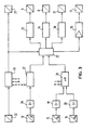
- a rotary evaporator which comprises an evaporator flask which can be heated with a heating device, a condenser which can be cooled by cooling water and a vacuum pump which is arranged to produce a vacuum in the condenser and in the evaporator flask
- a temperature pressure Control system for evaporating a mixture of components to arrange a temperature sensor measuring the system temperature and a pressure sensor measuring the system pressure on the condenser. Both sensors are connected via a measured value comparator to a shut-off valve arranged in the suction line of the vacuum pump in order to control the shut-off valve for switching the vacuum pump on and off as a function of adjustable measured value specifications.
- a shut-off valve arranged in the suction line of the vacuum pump in order to control the shut-off valve for switching the vacuum pump on and off as a function of adjustable measured value specifications.
- the invention characterized by the claims solves the problem of developing a method and a device of the specified type for the vacuum evaporation of a component mixture such that even without prior, at least approximate knowledge of the individual mixture components for their recovery, an improved efficiency, including a comparative one, is also achieved Time factor can be achieved and thus a greater degree of freedom is obtained for the setpoint specification of a system-related process parameter.
- the method according to the invention has the advantages that the inlet and outlet temperatures of the cooling medium can be measured easily and at the same time with the highest precision.
- An incipient condensation of the steam of a boiling mixture component thus represents the correspondingly precisely ascertainable point in time after which the vacuum pump is switched on between a difference occurs between these temperature measurements.
- a minimum controlled variable can thus be specified for this difference, so that when comparing with the difference threshold values oriented in the respective order of magnitude based on this specification, the points in time at which the vacuum pump for the recovery of a first mixture component is switched off and then again are recorded is switched on in order to subject the remaining mixture to a next setpoint / actual value comparison which is aimed at the possible recovery of a further mixture component with a different boiling point.
- the evaporator flask 1 is rotatably mounted in a piston holder 2 receiving a drive motor and is immersed in a rest position in a heating bath 3 that can be heated by means of a heating device.
- the heating bath 3 can be used to heat the component mixture to a boiling temperature that approximates the boiling point of its presumably easiest-boiling component is.
- the boiling temperature can also experience, by means of a vacuum pump 4, a shift regulated by a temperature-pressure control system to a low-value control variable including all mixture components.
- the vacuum pump 4 is designed as a water jet pump and connected to a condenser 6 with a suction line 5.
- the condenser 6 is connected to the evaporator flask 1 by means of a connecting tube 7 rotatably supported by the flask holder 2.
- a shut-off valve 9 which can be actuated by means of an electromagnet 8 is arranged in the suction line 5. When the shut-off valve 9 is open and the vacuum pump 4 is switched on, a vacuum is thus generated in the condenser 6 and in the evaporator flask 1, which vacuum can be measured by means of a pressure sensor 10.
- a specific boiling temperature is specified for the component mixture contained in the evaporating flask 1
- a lowering of the boiling pressure which also determines the boiling point of each mixture component when the vacuum is applied is therefore interrupted when the suction line 5 is shut off against the vacuum pump 4 by closing the shut-off valve 9.
- the shut-off valve 9 is closed at a point in time which coincides with the boiling point of a mixture component, its recovery as distillate can then be initiated.
- the distillate is obtained by condensation of the vapor of the mixture component transferred into the condenser 6 and collected in a collecting flask 11.
- the recovery as distillate can be accelerated by switching on the rotary drive for the evaporator flask 1 and the condenser 6 connected to it.
- the condenser 6 has a cooling coil 12 which is connected to an inlet line 13 and an outlet line 14 for cooling water.
- the inlet and outlet lines 13, 14 are each provided with a temperature sensor 15, 16 at a location close to the condenser 6, with which the inlet temperature IDE and the outlet temperature 1A of the cooling water can be measured.
- the shut-off valve 9 is open and the vacuum pump 4 is switched on, the vapor formed in the evaporator flask 1 is sucked off via the suction line 5, any substantial condensate formation on the cooling coil 12 is omitted, so that the two sensors 15, 16 have the same measured values for the inlet and outlet temperatures of the Cooling water can be detected.
- shutoff valve 18 which can also be actuated by means of an electromagnet 17, is arranged in the drain line 14.
- the temperature-pressure control system of the rotary evaporator is such that after an initial heating of the component mixture to a low-value control temperature maintained for the entire process, a mixture component begins to evaporate fairly quickly at the point in time when a with the shut-off valve 9 and the vacuum pump 4 switched on their vacuum is approximated.
- the lower temperature of the cooling water compared to the boiling temperature therefore experiences condensation during the initial phase the cooling coil 12 the aforementioned increase in the discharge line 14, so that there is a continuously increasing difference ⁇ between the outlet temperature ⁇ A and the inlet temperature ⁇ E.
- the course of curve I illustrates a possible process sequence for vacuum evaporation of a component mixture, the individual components of which are unknown.
- the mixture is first heated according to the above instructions by means of the heating bath 3 to a temperature which can be defined as a low-temperature control temperature which is based on the mixture and which is set on the basis of experience and which is maintained for the entire process.
- a temperature which can be defined as a low-temperature control temperature which is based on the mixture and which is set on the basis of experience and which is maintained for the entire process.
- the shut-off valve 9 is opened and the vacuum pump 4 is switched on at a point in time assumed with the coordinate origin.
- the vacuum generated in the evaporator system then drops the pressure curve I for an approximation of the component mixture to the boiling pressure of its lowest-boiling component.
- This drop in the pressure curve 1 during a first duty cycle A of the vacuum pump 4 is measured by means of the pressure sensor 10 and can be given a display connected in parallel for monitoring.
- the drop in the pressure curve I results in a practically synchronous rise in a second curve 11, which illustrates the difference ⁇ between the outlet temperature ⁇ A and the inlet temperature ⁇ E of the cooling water that occurs after the process starts and is taken into account as evidence of condensate formation taking place.
- the rise in the temperature curve II is monitored for the control of a first switch-off point B of the vacuum pump 4 by closing the check valve 9, which is controlled by actuation of the electromagnet 8.
- the monitoring is represented as a comparison of the difference between the temperature measurements for the cooling water, recorded with the two sensors 15, 16, with a predetermined upper difference threshold value, which is illustrated as a setpoint with the dashed line III.
- the first switch-off point B which is decisive for the vacuum pump 4, is thus obtained when a correspondence of the values is determined in this target / actual value comparison.
- a further drop in the pressure curve I is interrupted.
- a first mixture component can be recovered as a distillate collected with the collecting flask 11.
- the end of this recovery typically announces a drop in temperature curve II.
- this decrease in the temperature curve II is also monitored for a further setpoint / actual value comparison in order to switch the vacuum pump 4 on again at a next point in time C with the opening of the shutoff valve 9.
- the switch-on time C is obtained when a correspondence is established between the difference ⁇ again forming the actual value of the two temperature measurement values ⁇ A and ⁇ E for the cooling water and a differently specified lower difference threshold value, which is illustrated in FIG. 2 with the dashed line IV is.
- the pressure curve I continues to fall, which consequently triggers an increase in the temperature curve II again, provided that the mixture also contains a component which, in the vacuum which is then further reduced, has a consequently higher boiling point than that between at times B and C has recovered mixture component. If, during the monitoring of this repeated rise in the temperature curve II or with a corresponding target / actual value comparison, a correspondence with the upper difference threshold value III is again established, then the vacuum pump 4 is switched off again at a next point in time E, and consequently also recover heavier-boiling mixture components than distillate.
- the process sequence described above can be controlled automatically by means of a control device in which the pressure sensor 10 and the temperature sensors 15, 16 generate the measured value signals determining the process sequence.
- the measured value signals supplied by the temperature sensors for the inlet and outlet temperatures ⁇ E and ⁇ A of the cooling water are amplified by amplifiers 19 and 20 before the difference ⁇ is formed from them with a differential circuit 21.
- a differential signal generated by the differential circuit 21 is supplied to a logic circuit 22, which is designed for a comparison of the differential signal thus following the temperature curve II with upper and lower differential threshold value signals in accordance with the specifications according to lines III and IV in FIG.
- the logic circuit 22 therefore activates a switch-on signal to a control device 23 of the vacuum pump 4 and a switch-off signal to a control device 24 of the check valve 9
- the supplied electromagnet 8 with which the switch-on times C and F and the switch-off times B and E can be controlled.
- the logic circuit 22 is also optimally designed for supplying a control signal following each switch-off signal with a time delay to a control device 25 of the condenser 6 which regulates the flow of the cooling water.
- the control signal for this control device can be obtained in such a way that each rise in the temperature curve II, as shown in FIG. 2, not only on reaching the upper differential threshold value 111, but also on reaching a higher one, indicated by the dash-dotted line V. Control value is monitored. If the logic circuit 22 subsequently also determines a match with this control value V at a switch-off time B or E, the control device 25 regulates the amount of cooling water flowing through the cooling coil 12 of the condenser 6 until the temperature curve II again leaves a control level of the cooling water temperature specified with the control value.
- the regulating device 25 can be connected to a control device for the electromagnet 17 of the check valve 18.
- the logic circuit 22 is also optimally designed for linking the switch-on and switch-off signals supplied to the control devices 23 and 24 and the control signal supplied to the control device 25 with the measured value signal supplied by the pressure sensor 10 for the system pressure p. Similar to the measured value signals of the temperature sensors 15, 16, the measured value signal of the pressure sensor 10 is also amplified by an amplifier 26 before it is supplied to the logic circuit 22 via an evaluation circuit 27 for this connection.
- the evaluation circuit 27 can evaluate the amplified measured value signal a of the pressure sensor 10, for example for forwarding to a signaling device 28, so that a monitoring message can be displayed, for example, to a display device 29 of the control device when it is switched.
- the signaling device 28 can then also be optimally supplied with the amplified measured value signals b and c of the two temperature sensors 15, 16.
- the evaluation circuit 27 can be designed in such a way that, by means of the logic circuit 22, the delivery of a control signal to a control device 30 for the rotary drive 31 of the evaporator system is omitted if the presence of a leak that is also displayed on the display device 29 is reported during the evaluation .
- further monitoring devices 32 can also be connected to the display device 29 via the signaling device 28, with which an automatic control of the process sequence is optimally monitored, such working signals analogously to the measured value signal of the pressure sensor 10 also being able to optimally experience a link to the logic circuit 22.
- the vacuum evaporation described above can be applied to any distillation and rectification of mixtures conventionally practiced in the chemical industry, including azeotropic mixtures.
- the method is not limited to use in a rotary evaporator, although it is best suited for this purpose and an average recovery of at least about 99% of all boiling components of a mixture can be achieved without any prior knowledge of the composition.
- the temperature measurement of the cooling medium that is practiced for the automatic control of the process does not necessarily have to be carried out in the immediate vicinity of the cooling device, but instead can also be laid in a measuring circuit connected in parallel with the cooling device.
- the heat flow sensor For a further alternative of this measuring principle, it is also possible to evaluate the measured value signal of a heat flow sensor as a corresponding manipulated variable instead of the difference between the two temperature measured values for the coolant, the heat flow sensor having to be arranged in the flow path of the steam of the mixture components by which the cause of the difference in the To measure temperature measurements of the cooling water forming the heat flow.
Landscapes
- Chemical & Material Sciences (AREA)
- Chemical Kinetics & Catalysis (AREA)
- Engineering & Computer Science (AREA)
- Automation & Control Theory (AREA)
- Vaporization, Distillation, Condensation, Sublimation, And Cold Traps (AREA)
Applications Claiming Priority (2)
| Application Number | Priority Date | Filing Date | Title |
|---|---|---|---|
| DE3607605 | 1986-03-07 | ||
| DE19863607605 DE3607605A1 (de) | 1986-03-07 | 1986-03-07 | Verfahren und vorrichtung zum vakuum-verdampfen eines komponentengemisches |
Publications (3)
| Publication Number | Publication Date |
|---|---|
| EP0236813A2 EP0236813A2 (de) | 1987-09-16 |
| EP0236813A3 EP0236813A3 (en) | 1988-09-21 |
| EP0236813B1 true EP0236813B1 (de) | 1990-06-27 |
Family
ID=6295791
Family Applications (1)
| Application Number | Title | Priority Date | Filing Date |
|---|---|---|---|
| EP87102349A Expired - Lifetime EP0236813B1 (de) | 1986-03-07 | 1987-02-19 | Verfahren und Vorrichtung zum Vakuum-Verdampfen eines Komponentengemisches |
Country Status (3)
| Country | Link |
|---|---|
| EP (1) | EP0236813B1 (enExample) |
| JP (1) | JPS62213802A (enExample) |
| DE (2) | DE3607605A1 (enExample) |
Families Citing this family (17)
| Publication number | Priority date | Publication date | Assignee | Title |
|---|---|---|---|---|
| CH670773A5 (enExample) * | 1986-06-13 | 1989-07-14 | Buechi Lab Tech | |
| CH681279A5 (en) * | 1989-04-25 | 1993-02-26 | Buechi Lab Tech | Liq. evapn. and condensation process - uses detection system to avoid noxious component escape through vacuum system |
| GB8916081D0 (en) * | 1989-07-13 | 1989-08-31 | Kerry Ultrasonics | Methods of and apparatus for purifying a liquid |
| FR2657271B1 (fr) * | 1990-01-23 | 1992-05-15 | Sanofi Sa | Appareillage d'evaporation sous vide. |
| DE4218451A1 (de) * | 1992-06-04 | 1993-12-09 | Transferon Waeschereimasch | Verfahren zur Aufbereitung verunreinigter höhersiedender Lösemittel sowie Vorrichtung zur Durchführung des Verfahrens |
| EP0685248A1 (de) * | 1994-06-03 | 1995-12-06 | Büchi Labortechnik AG | Verfahren und Vorrichtung zum Destillieren von Flüssigkeiten |
| ATE171638T1 (de) * | 1995-03-01 | 1998-10-15 | Baumann Didda Maria Janina | Verfahren und vorrichtung zur wiederaufbereitung eines verunreinigten lösemittels |
| US6117275A (en) * | 1996-03-01 | 2000-09-12 | Didda Maria Janina Baumann | Process and device for regenerating a contaminated solvent |
| DE19627641C1 (de) * | 1996-07-09 | 1998-01-15 | Heinz Dipl Ing Ploechinger | Verfahren und Vorrichtung zum Steuern des Drucks in einer Vakuumkammer einer Destillations- oder Sublimations-Vorrichtung |
| FR2786708B1 (fr) * | 1998-12-03 | 2001-02-09 | Jean Pierre Martel | Appareil de traitement continu et rapide de liquides, comportant des moyens d'echange de matiere entre des vapeurs volatiles ou des gaz et leur liquide generateur |
| ATE331210T1 (de) * | 1999-02-09 | 2006-07-15 | Genevac Ltd | Verbesserte unterdrucksteuerung in verdampfern |
| JP2008237943A (ja) * | 2007-03-23 | 2008-10-09 | Sanyo Electric Co Ltd | 減圧蒸留方法及び減圧蒸留装置 |
| DE102008051364B4 (de) * | 2008-10-15 | 2012-03-15 | Ika-Werke Gmbh & Co. Kg | Rotationsverdampfer |
| JP5892485B2 (ja) * | 2011-12-26 | 2016-03-23 | 地方独立行政法人東京都立産業技術研究センター | 降水降下物などの自動蒸発濃縮器 |
| DE102012221887A1 (de) * | 2012-11-29 | 2014-06-05 | Hans Heidolph Gmbh & Co. Kg | Verfahren und Vorrichtung zur Vakuumdestillation |
| EP2946820B1 (de) * | 2014-05-20 | 2025-06-18 | Büchi Labortechnik AG | Verfahren zum betrieb eines verdampfungssystems und verdampfungssystem |
| CN114656004B (zh) * | 2022-03-28 | 2022-11-08 | 嘉兴市磁海无损检测设备制造有限公司 | 一种基于真空蒸发的污水处理装置及污水处理方法 |
Family Cites Families (2)
| Publication number | Priority date | Publication date | Assignee | Title |
|---|---|---|---|---|
| DE3413385A1 (de) * | 1984-04-10 | 1985-10-17 | Peter 7600 Offenburg Huber | Verfahren zum eindampfen von fluessigkeiten unter vakuum sowie vorrichtung zur durchfuehrung des verfahrens |
| DE8524023U1 (de) * | 1985-08-22 | 1985-11-28 | Struve, Armin, Dipl.-Ing., 5090 Leverkusen | Vorrichtung zum Destillieren, Abdestillieren und Rektifizieren von Flüssigkeiten unter Vakuum, insbesondere Lösungsmitteln, vornehmlich im Labor- und Technikumsbetrieb |
-
1986
- 1986-03-07 DE DE19863607605 patent/DE3607605A1/de active Granted
-
1987
- 1987-02-19 DE DE8787102349T patent/DE3763362D1/de not_active Expired - Lifetime
- 1987-02-19 EP EP87102349A patent/EP0236813B1/de not_active Expired - Lifetime
- 1987-03-05 JP JP62051205A patent/JPS62213802A/ja active Pending
Also Published As
| Publication number | Publication date |
|---|---|
| DE3607605A1 (de) | 1987-09-10 |
| EP0236813A3 (en) | 1988-09-21 |
| DE3607605C2 (enExample) | 1988-03-17 |
| EP0236813A2 (de) | 1987-09-16 |
| DE3763362D1 (de) | 1990-08-02 |
| JPS62213802A (ja) | 1987-09-19 |
Similar Documents
| Publication | Publication Date | Title |
|---|---|---|
| EP0236813B1 (de) | Verfahren und Vorrichtung zum Vakuum-Verdampfen eines Komponentengemisches | |
| EP0284785B1 (de) | Verfahren und Vorrichtung zur Dichtheitskontrolle von zwei hintereinander in einer Fluidleitung angeordneten Ventilen | |
| DE3529956C2 (enExample) | ||
| DE3517215C2 (enExample) | ||
| DE19737717C2 (de) | Verfahren zum Steuern des Siededrucks in einem Rotationsverdampfer sowie Rotationsverdampfer zur Durchführung dieses Verfahrens | |
| DE2902270C2 (de) | Verfahren zum Abkühlen von Backgut | |
| DE3413385A1 (de) | Verfahren zum eindampfen von fluessigkeiten unter vakuum sowie vorrichtung zur durchfuehrung des verfahrens | |
| DE2940045C2 (enExample) | ||
| DE3526024C2 (enExample) | ||
| DE3307594A1 (de) | Dampfkessel mit elektrischer widerstandsheizung | |
| DE4039643A1 (de) | Verfahren und vorrichtung zum ueberwachen des heizwasserumlaufs bei einem gaswasserheizer | |
| EP2986186B1 (de) | Verfahren zur steuerung des heissgetränkezubereitungsgeräts mit kontrollierter dampferzeugung | |
| DE3235642A1 (de) | Einrichtung zur elektrischen abtauregelung fuer den verdampfer einer kaelteanlage | |
| DE3517220A1 (de) | Kaelteanlage mit einem ausblasesystem und verfahren zum betreiben derselben | |
| EP1199015A2 (de) | Dampfgargerät mit einer kalibrierungslosen Sollsiedetemperatur | |
| CH641888A5 (en) | Method of extracting gases from containers | |
| CH671435A5 (enExample) | ||
| EP1375214B1 (de) | Verfahren zur Ansteuerung eines Heizgerätes, Heizgerät mit einer zur Durchführung dieses Verfahrens ausgebildeten Ansteuervorrichtung, und Verfahren zum Ermitteln eines Wertes | |
| DE3225622C2 (de) | Verfahren und Vorrichtung zur Regelung der Luftfeuchtigkeit | |
| EP0219450A1 (de) | Vorrichtung zur Vakuumregulierung | |
| DE3220593C1 (de) | Verfahren zum Beenden des Abtauens des Verdampfers einer Luft-Wasser Wärmepumpe | |
| EP1248061A1 (de) | Verfahren zum Trocknen von Feststoffisolationen eines elektrischen Gerätes | |
| EP2280230A2 (de) | Verfahren zur Überwachung des Verschmutzungszustandes eines Wärmetauschers an einem Heizgerät | |
| EP0237855A2 (de) | Verfahren und Vorrichtung zum intermittierenden Reinigen von Eindampfanlagen | |
| DE2722066A1 (de) | Verfahren zum ein- bzw. abschalten eines rotationsverdampfers |
Legal Events
| Date | Code | Title | Description |
|---|---|---|---|
| PUAI | Public reference made under article 153(3) epc to a published international application that has entered the european phase |
Free format text: ORIGINAL CODE: 0009012 |
|
| AK | Designated contracting states |
Kind code of ref document: A2 Designated state(s): CH DE FR GB IT LI NL SE |
|
| PUAL | Search report despatched |
Free format text: ORIGINAL CODE: 0009013 |
|
| AK | Designated contracting states |
Kind code of ref document: A3 Designated state(s): CH DE FR GB IT LI NL SE |
|
| 17P | Request for examination filed |
Effective date: 19880929 |
|
| 17Q | First examination report despatched |
Effective date: 19890616 |
|
| GRAA | (expected) grant |
Free format text: ORIGINAL CODE: 0009210 |
|
| AK | Designated contracting states |
Kind code of ref document: B1 Designated state(s): CH DE FR GB IT LI NL SE |
|
| PG25 | Lapsed in a contracting state [announced via postgrant information from national office to epo] |
Ref country code: IT Free format text: LAPSE BECAUSE OF FAILURE TO SUBMIT A TRANSLATION OF THE DESCRIPTION OR TO PAY THE FEE WITHIN THE PRE;WARNING: LAPSES OF ITALIAN PATENTS WITH EFFECTIVE DATE BEFORE 2007 MAY HAVE OCCURRED AT ANY TIME BEFORE 2007. THE CORRECT EFFECTIVE DATE MAY BE DIFFERENT FROM THE ONE RECORDED.SCRIBED TIME-LIMIT Effective date: 19900627 Ref country code: NL Effective date: 19900627 Ref country code: FR Effective date: 19900627 Ref country code: GB Effective date: 19900627 Ref country code: SE Effective date: 19900627 |
|
| REF | Corresponds to: |
Ref document number: 3763362 Country of ref document: DE Date of ref document: 19900802 |
|
| EN | Fr: translation not filed | ||
| NLV1 | Nl: lapsed or annulled due to failure to fulfill the requirements of art. 29p and 29m of the patents act | ||
| GBV | Gb: ep patent (uk) treated as always having been void in accordance with gb section 77(7)/1977 [no translation filed] | ||
| PGFP | Annual fee paid to national office [announced via postgrant information from national office to epo] |
Ref country code: CH Payment date: 19910226 Year of fee payment: 5 |
|
| PLBE | No opposition filed within time limit |
Free format text: ORIGINAL CODE: 0009261 |
|
| STAA | Information on the status of an ep patent application or granted ep patent |
Free format text: STATUS: NO OPPOSITION FILED WITHIN TIME LIMIT |
|
| PGFP | Annual fee paid to national office [announced via postgrant information from national office to epo] |
Ref country code: DE Payment date: 19910430 Year of fee payment: 5 |
|
| 26N | No opposition filed | ||
| PG25 | Lapsed in a contracting state [announced via postgrant information from national office to epo] |
Ref country code: CH Effective date: 19920229 Ref country code: LI Effective date: 19920229 |
|
| REG | Reference to a national code |
Ref country code: CH Ref legal event code: PL |
|
| PG25 | Lapsed in a contracting state [announced via postgrant information from national office to epo] |
Ref country code: DE Effective date: 19921103 |