EP0236540B1 - Vorrichtung zur temperaturabhängigen Messpunktverstellung zweier Maschinenteile - Google Patents
Vorrichtung zur temperaturabhängigen Messpunktverstellung zweier Maschinenteile Download PDFInfo
- Publication number
- EP0236540B1 EP0236540B1 EP86110454A EP86110454A EP0236540B1 EP 0236540 B1 EP0236540 B1 EP 0236540B1 EP 86110454 A EP86110454 A EP 86110454A EP 86110454 A EP86110454 A EP 86110454A EP 0236540 B1 EP0236540 B1 EP 0236540B1
- Authority
- EP
- European Patent Office
- Prior art keywords
- machine part
- scale
- headstock
- attached
- transverse bolt
- Prior art date
- Legal status (The legal status is an assumption and is not a legal conclusion. Google has not performed a legal analysis and makes no representation as to the accuracy of the status listed.)
- Expired - Lifetime
Links
- 230000001419 dependent effect Effects 0.000 title description 5
- 238000006073 displacement reaction Methods 0.000 claims description 6
- 239000000463 material Substances 0.000 claims description 5
- 238000005259 measurement Methods 0.000 description 6
- 238000010438 heat treatment Methods 0.000 description 4
- 238000003801 milling Methods 0.000 description 3
- XEEYBQQBJWHFJM-UHFFFAOYSA-N Iron Chemical compound [Fe] XEEYBQQBJWHFJM-UHFFFAOYSA-N 0.000 description 2
- 230000000694 effects Effects 0.000 description 2
- 229910001369 Brass Inorganic materials 0.000 description 1
- 230000005540 biological transmission Effects 0.000 description 1
- 239000010951 brass Substances 0.000 description 1
- 230000003111 delayed effect Effects 0.000 description 1
- 238000009413 insulation Methods 0.000 description 1
- 229910052742 iron Inorganic materials 0.000 description 1
- 229910000679 solder Inorganic materials 0.000 description 1
Images
Classifications
-
- G—PHYSICS
- G01—MEASURING; TESTING
- G01B—MEASURING LENGTH, THICKNESS OR SIMILAR LINEAR DIMENSIONS; MEASURING ANGLES; MEASURING AREAS; MEASURING IRREGULARITIES OF SURFACES OR CONTOURS
- G01B5/00—Measuring arrangements characterised by the use of mechanical techniques
- G01B5/0011—Arrangements for eliminating or compensation of measuring errors due to temperature or weight
- G01B5/0014—Arrangements for eliminating or compensation of measuring errors due to temperature or weight due to temperature
-
- Y—GENERAL TAGGING OF NEW TECHNOLOGICAL DEVELOPMENTS; GENERAL TAGGING OF CROSS-SECTIONAL TECHNOLOGIES SPANNING OVER SEVERAL SECTIONS OF THE IPC; TECHNICAL SUBJECTS COVERED BY FORMER USPC CROSS-REFERENCE ART COLLECTIONS [XRACs] AND DIGESTS
- Y10—TECHNICAL SUBJECTS COVERED BY FORMER USPC
- Y10S—TECHNICAL SUBJECTS COVERED BY FORMER USPC CROSS-REFERENCE ART COLLECTIONS [XRACs] AND DIGESTS
- Y10S33/00—Geometrical instruments
- Y10S33/19—Thermal expansive
-
- Y—GENERAL TAGGING OF NEW TECHNOLOGICAL DEVELOPMENTS; GENERAL TAGGING OF CROSS-SECTIONAL TECHNOLOGIES SPANNING OVER SEVERAL SECTIONS OF THE IPC; TECHNICAL SUBJECTS COVERED BY FORMER USPC CROSS-REFERENCE ART COLLECTIONS [XRACs] AND DIGESTS
- Y10—TECHNICAL SUBJECTS COVERED BY FORMER USPC
- Y10T—TECHNICAL SUBJECTS COVERED BY FORMER US CLASSIFICATION
- Y10T408/00—Cutting by use of rotating axially moving tool
- Y10T408/16—Cutting by use of rotating axially moving tool with control means energized in response to activator stimulated by condition sensor
-
- Y—GENERAL TAGGING OF NEW TECHNOLOGICAL DEVELOPMENTS; GENERAL TAGGING OF CROSS-SECTIONAL TECHNOLOGIES SPANNING OVER SEVERAL SECTIONS OF THE IPC; TECHNICAL SUBJECTS COVERED BY FORMER USPC CROSS-REFERENCE ART COLLECTIONS [XRACs] AND DIGESTS
- Y10—TECHNICAL SUBJECTS COVERED BY FORMER USPC
- Y10T—TECHNICAL SUBJECTS COVERED BY FORMER US CLASSIFICATION
- Y10T409/00—Gear cutting, milling, or planing
- Y10T409/30—Milling
- Y10T409/303976—Milling with means to control temperature or lubricate
Definitions
- the invention relates to a device for temperature-dependent measuring point adjustment of two relatively movable machine parts of the type specified in the preamble of claim 1.
- a phenomenon influencing the accuracy of relative displacement movements of two machine parts lies in the thermal expansion of the machine parts in the event of temperature changes such as occur, for example, when machine tools start up. Such heating is primarily caused by bearing friction of the components rotating in the respective machine parts, e.g. the work spindle and its drive shafts in the headstock of a machine tool. Since the effective length of the scales used corresponds to the maximum feed path of the movable machine part, but the heated machine parts are often longer than this maximum travel distance, these temperature changes lead to undesirable zero point displacements of the scale. These disadvantageous effects occur particularly in program-controlled machine tools with a horizontally movable headstock, in which the scale is attached to the headstock and a reading head is attached to the stand.
- the program control of these machines is designed so that their position control circuit detects and compensates for undesired relative movements between the headstock that carries the scale and the stationary reading head. If, however, the thermal expansions of the headstock itself and the spindle mounted in the headstock have different values, the reading head cannot record these differences, so that data containing errors are fed to the position control circuit accordingly.
- a measuring device for machine tools with automatic temperature compensation in which the measurement and processing inaccuracies caused by thermal expansion are practically avoided by arranging an expansion rod made of a material with a high thermal expansion coefficient parallel to the axis of the headstock and with its rear End is attached to the headstock and with its front end to the scale, the thermal expansion of the expansion rod should be approximately equal to the thermal expansion of the headstock.
- the expansion rod in direct contact with the headstock also heats up, the end of which extends towards the front and carries along the scale attached to it.
- the elongation of the expansion rod corresponds to the thermal expansion of the entire headstock in the longitudinal direction, including a vertical milling head, if applicable, on the front.
- this known measuring system has proven to be functional in practice, there were still certain measuring errors which relate to the arrangement of the expansion rod on the outer surface of the machine part, i.e. of the headstock. In start-up mode in particular there were measurement errors due to a delayed heat transfer from the thermally particularly highly stressed inner components to the scale.
- the temperatures prevailing inside the moving machine part cannot be recorded and taken into account, which in the case of headstocks has the result that the elongation of the work spindle mounted in the headstock, including its spindle sleeves, is greater than the thermal expansion of the headstock itself due to the higher temperatures prevailing inside .
- the resulting measurement errors cannot be compensated for and must be accepted.
- a device for measuring the relative position of two machine parts with compensation for thermal changes in length in which a scale and an expansion rod are arranged axially parallel next to each other on a side surface of the movable machine part, in this case a headstock, and with attack their respective front ends on each leg of a double-armed swivel element.
- the axially parallel to the scale expansion element consists of a material with a high coefficient of thermal expansion, so that it expands more than a certain operating temperature of the first machine part and causes a rotary movement of the pivoting element, which is converted into a corresponding displacement movement of the scale.
- the swivel lever bearing on the moving machine part can be adjusted to change the gear ratio of the swivel movements. Since in this known device all components are in direct contact with the first machine part, they are also exposed to the effects of heat, which affects the measurement accuracy.
- the object of the invention is to provide a generic device for temperature-dependent measurement To create point adjustment of two relatively movable machine parts, with which an improved compensation of different thermal expansions of these machine parts or the elements built into them is achieved.
- the thermal expansions of the cross bolt which is heated particularly quickly and intensively, are converted into longitudinal displacements of the scale by means of the angular lifting, the thermal expansion of the transverse bolt being transferred into an adjusting movement of the scale which is adapted to the respective circumstances by means of a corresponding translation factor of the angular lever.
- the inner end of the cross bolt advantageously lies in the most heated zones of the machine part, the temperatures prevailing in these areas can also be taken into account and the elongations caused thereby, e.g. of a work spindle with a quill.
- the material of the cross bolt does not have to relate to the material and thus the thermal expansion of the machine part, i.e. its thermal expansion coefficient.
- the determination of the scale on the movable first machine part by means of the leaf springs ensures a constantly effective restoring force of the scale and a free distance from the headstock, which without additional components brings about effective thermal insulation of the scale from the heated first machine part.
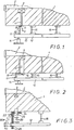
- a spindle 2 is rotatably mounted in a headstock 1.
- a cross bore 4 is formed in the headstock 1, in which a cross bolt 5 is received.
- the inner end of this cross bolt 5 lies directly on the outer bearing shell of the spindle bearing 3 or is in another way, e.g. through a threaded section, fixed in the bore.
- the pin 5, which is otherwise axially displaceable in the bore 4 protrudes with its tip out of the bore 4 and presses against the horizontal leg 6 of an angle lever 7, which is pivotable in its angle about a horizontal axis 8 in a bracket 9 fastened to the headstock 1 is stored.
- the vertical leg 10 of the angle lever 7 in the drawing is constantly in contact with a pressure piece 11 which is fastened to the inner surface of a scale 12.
- This scale 12 bears markings 13 on its outside, which can be read by a stationary reading head 14.
- the scale 12 is attached to the headstock 1 by two leaf springs 15, in such a way that there is constant pressure contact between the vertical leg 10 of the bell crank and the pressure piece attached to the scale 12.
- the cross bolt 5 expands according to its thermal expansion coefficient by an amount corresponding to the respective temperature and pivots the angle lever 7, the vertical leg 10 of which in the drawing, the scale against the force of the leaf springs 15 by a corresponding amount moves horizontally.
- FIG. 2 corresponds essentially to that of FIG. 1, but with the transverse bolt 5 having a bevelled end face 16 which bears against the correspondingly inclined end face of an angle lever in the form of a slide 17 in constant pressure contact.
- This slide 17 is displaceable in dashed guides on the headstock and presses when the bolt 5 is elongated against the pressure piece 11 on the scale 12, which is thereby displaced horizontally by a corresponding amount.
- the scale 12 is laterally attached to the headstock by means of the two leaf springs 15, so that the thermal expansions of the headstock are not transferred to the heat-insulated scale 12.
- the slide 17 of the embodiment according to FIG. 2 can be replaced by a two-armed pivot lever which is rotatably mounted on the side surface of the headstock 1 and has an inclined surface or a roller on its shorter arm, which with resilient pressure contact on the inclined surface 16 of the Cross bolt 5 abuts. To achieve the necessary translation, the longer end of the lever arm can rest on the pressure piece 11.
- a bimetallic element 20 can be used as an effective element of the deflection gear, as shown in FIG. 3.
- This bimetal element 20 is an angle profile, which consists of two L-shaped angles 21 and 22, which are continuously and firmly connected to one another by a large-area solder connection 23.
- the outer angle 22 can e.g. made of sheet iron and the inner bracket 21 made of brass.
- the outer angle 22 is fastened with its one leg 24 directly to the headstock 1 by means of a screw bolt 25, specifically to the front end part of the headstock 1, which is sensitive to temperature changes.
- At the end of the freely projecting other leg 26 of the bimetal element 20 is the scale 12 attached with its front end.
- An arcuate bimetal element 20 ' is shown in dashed lines in FIG. 3.
Landscapes
- Physics & Mathematics (AREA)
- General Physics & Mathematics (AREA)
- Automatic Control Of Machine Tools (AREA)
- A Measuring Device Byusing Mechanical Method (AREA)
- Length Measuring Devices With Unspecified Measuring Means (AREA)
Applications Claiming Priority (2)
| Application Number | Priority Date | Filing Date | Title |
|---|---|---|---|
| DE19863604550 DE3604550A1 (de) | 1986-02-13 | 1986-02-13 | Vorrichtung zur temperaturabhaengigen messpunktverstellung zweier maschinenteile |
| DE3604550 | 1986-02-13 |
Publications (2)
| Publication Number | Publication Date |
|---|---|
| EP0236540A1 EP0236540A1 (de) | 1987-09-16 |
| EP0236540B1 true EP0236540B1 (de) | 1990-04-04 |
Family
ID=6294032
Family Applications (1)
| Application Number | Title | Priority Date | Filing Date |
|---|---|---|---|
| EP86110454A Expired - Lifetime EP0236540B1 (de) | 1986-02-13 | 1986-07-29 | Vorrichtung zur temperaturabhängigen Messpunktverstellung zweier Maschinenteile |
Country Status (4)
| Country | Link |
|---|---|
| US (1) | US4728232A (enExample) |
| EP (1) | EP0236540B1 (enExample) |
| JP (1) | JPS62187204A (enExample) |
| DE (2) | DE3604550A1 (enExample) |
Families Citing this family (12)
| Publication number | Priority date | Publication date | Assignee | Title |
|---|---|---|---|---|
| DE3633573C1 (de) * | 1986-10-02 | 1988-02-04 | Heidenhain Gmbh Dr Johannes | Vorrichtung zur Kompensation von temperaturbedingten Verlagerungen eines Maschinenpunktes,insbesondere der temperaturbedingten Verlagerung einer Arbeitsspindelachse gegenueber einem Maschinen-Referenzpunkt |
| EP0348660B1 (de) * | 1988-06-29 | 1992-02-19 | Dr. Johannes Heidenhain GmbH | Positionsmesseinrichtung |
| US5036630A (en) * | 1990-04-13 | 1991-08-06 | International Business Machines Corporation | Radial uniformity control of semiconductor wafer polishing |
| US5303458A (en) * | 1992-03-31 | 1994-04-19 | Hardinge Brothers, Inc. | Method and apparatus for detecting and compensating thermal growth in machine tools |
| JPH06285731A (ja) * | 1992-04-03 | 1994-10-11 | Murata Mach Ltd | 複合加工機 |
| DE4223841A1 (de) * | 1992-07-20 | 1994-01-27 | Ems Technik Gmbh | Justiervorrichtung |
| JP3982890B2 (ja) * | 1997-08-06 | 2007-09-26 | 富士通株式会社 | 研磨装置、この装置に用いられる研磨治具、及び、この研磨治具に取り付けられる被研磨物取付部材 |
| WO2002003025A1 (en) * | 2000-06-30 | 2002-01-10 | Unova Ip Corp. | Method for determining effective coefficient of thermal expansion |
| ATE328263T1 (de) * | 2001-07-16 | 2006-06-15 | Werth Messtechnik Gmbh | Koordinatenmessgerät mit zusatzwärmequelle |
| CN102015203A (zh) * | 2008-03-17 | 2011-04-13 | 克里斯托弗·A·苏普罗克 | 智能机加工系统及其智能刀具夹具 |
| DE102010003303A1 (de) * | 2010-03-25 | 2011-09-29 | Deckel Maho Seebach Gmbh | Verfahren und Vorrichtung zum Kompensieren einer temperaturabhängigen Lageveränderung an einer Werkzeugmaschine |
| DE202010008979U1 (de) * | 2010-11-08 | 2012-02-09 | Starrag Heckert Ag | Einrichtung zur Lagekorrektur von Elementen einer Werkzeugmaschine und Kompensationselement dafür |
Family Cites Families (11)
| Publication number | Priority date | Publication date | Assignee | Title |
|---|---|---|---|---|
| US2727796A (en) * | 1955-01-11 | 1955-12-20 | G M Giannini & Co Inc | Temperature compensation of shaft end play and the like |
| USB295344I5 (enExample) * | 1958-02-03 | |||
| DE2558625A1 (de) * | 1975-12-24 | 1977-07-14 | Norte Klessmann & Co Kg | Werkzeugmaschine, insbesondere bohr- oder fraesmaschine |
| SU764960A1 (ru) * | 1978-01-05 | 1980-09-23 | Московский станкоинструментальный институт | Механизм точной подачи |
| DE3116827C2 (de) * | 1981-02-23 | 1983-10-20 | Maho Werkzeugmaschinenbau Babel & Co, 8962 Pfronten | Meßeinrichtung für Werkzeugmaschinen zum Erfassen von geradlinigen Relativbewegungen zweier Maschinenteile |
| DE3106701C2 (de) * | 1981-02-23 | 1982-12-02 | Maho Werkzeugmaschinenbau Babel & Co, 8962 Pfronten | Meßsystem für Werkzeugmaschinen |
| IT1156613B (it) * | 1982-06-28 | 1987-02-04 | Cima | Macchina dentatrice |
| DE3316081A1 (de) * | 1983-05-03 | 1984-11-08 | Dr. Johannes Heidenhain Gmbh, 8225 Traunreut | Messeinrichtung |
| DE3316082A1 (de) * | 1983-05-03 | 1984-11-08 | Dr. Johannes Heidenhain Gmbh, 8225 Traunreut | Messeinrichtung |
| DE3320529A1 (de) * | 1983-06-07 | 1984-12-13 | Maschinenfabrik Mikron AG, Bienne | Einrichtung zur kompensation temperaturbedingter verschiebungen einer arbeitsspindel gegenueber einem am spindelschlitten im abstand von der arbeitsspindel angebrachten massstab |
| DE3418583C1 (de) * | 1984-05-18 | 1985-09-12 | Gebr. Heller Maschinenfabrik GmbH, 7440 Nürtingen | Kurbelwellenfraesmaschine oder dergleichen Fraesmaschine |
-
1986
- 1986-02-13 DE DE19863604550 patent/DE3604550A1/de active Granted
- 1986-07-29 DE DE8686110454T patent/DE3670150D1/de not_active Expired - Fee Related
- 1986-07-29 EP EP86110454A patent/EP0236540B1/de not_active Expired - Lifetime
- 1986-11-26 JP JP61281634A patent/JPS62187204A/ja active Pending
- 1986-12-12 US US06/941,058 patent/US4728232A/en not_active Expired - Fee Related
Also Published As
| Publication number | Publication date |
|---|---|
| EP0236540A1 (de) | 1987-09-16 |
| DE3604550A1 (de) | 1987-08-27 |
| US4728232A (en) | 1988-03-01 |
| DE3670150D1 (de) | 1990-05-10 |
| DE3604550C2 (enExample) | 1989-02-09 |
| JPS62187204A (ja) | 1987-08-15 |
Similar Documents
| Publication | Publication Date | Title |
|---|---|---|
| EP0236540B1 (de) | Vorrichtung zur temperaturabhängigen Messpunktverstellung zweier Maschinenteile | |
| DE3316081C2 (enExample) | ||
| EP0123895B1 (de) | Messeinrichtung | |
| DE3719409C2 (enExample) | ||
| EP2024110B1 (de) | Vorrichtung zum messen der breite und/oder der bandlage eines metallbandes oder einer bramme | |
| DE3106701C2 (de) | Meßsystem für Werkzeugmaschinen | |
| CH648238A5 (de) | Vorrichtung zum durchbiegen einer druckwalze einer rotationsdruckmaschine. | |
| DE102019107189A1 (de) | Einrichtung und Verfahren zum thermischen Fügen von zwei Werkstücken | |
| DE3627546C1 (de) | Vorrichtung zur Kompensation der Waermedehnung zweier relativ bewegbarer Maschinenteile | |
| DE3427909C2 (de) | Farbdosiereinrichtung | |
| EP1392918B1 (de) | Vorrichtung, verfahren und anordnung zum andrücken zweier aneinander annäherbarer achsparalleler walzen in einer einrichtung zur herstellung oder/und behandlung einer materialbahn | |
| DE2643017C3 (de) | Durchbiegungseinstellwalze für Papiermaschinen | |
| EP0094584B1 (de) | Farbkasten für Druckmaschinen | |
| DE2900896C2 (de) | Gewinde-Meßgerät | |
| DE4127344C2 (enExample) | ||
| DE3116827C2 (de) | Meßeinrichtung für Werkzeugmaschinen zum Erfassen von geradlinigen Relativbewegungen zweier Maschinenteile | |
| DE29716031U1 (de) | Verstellvorrichtung für ein Walzenpaar zum Einstellen eines Walzenspaltes | |
| DE2105654C3 (de) | Befestigungsvorrichtung für ein Reibrad-LängenmeBgerät | |
| DE10330955B4 (de) | Positionsmessgerät und Verfahren zur Montage eines derartigen Positionsmessgerätes | |
| DE3347486A1 (de) | Dickenmessvorrichtung fuer blattgut | |
| DE102022125376B4 (de) | Messrolle zum Messen eines Bandzugs und Verfahren | |
| DE2643018B2 (de) | Walzenpresse mit einer Durchbiegungseinstellwalze z.B. für Papiermaschinen | |
| EP0123018A1 (de) | Messsystem mit einer Einrichtung zur Fehlerkorrektur | |
| DE10060714A1 (de) | Walzenpaaranordnung | |
| CH593724A5 (en) | Flexure compensation roll for rolling mills - where angle of hydraulic flexure compensation elements can be varied |
Legal Events
| Date | Code | Title | Description |
|---|---|---|---|
| PUAI | Public reference made under article 153(3) epc to a published international application that has entered the european phase |
Free format text: ORIGINAL CODE: 0009012 |
|
| AK | Designated contracting states |
Kind code of ref document: A1 Designated state(s): CH DE FR GB IT LI |
|
| RAP1 | Party data changed (applicant data changed or rights of an application transferred) |
Owner name: MAHO AKTIENGESELLSCHAFT |
|
| 17P | Request for examination filed |
Effective date: 19871019 |
|
| 17Q | First examination report despatched |
Effective date: 19890307 |
|
| GRAA | (expected) grant |
Free format text: ORIGINAL CODE: 0009210 |
|
| AK | Designated contracting states |
Kind code of ref document: B1 Designated state(s): CH DE FR GB IT LI |
|
| ITF | It: translation for a ep patent filed | ||
| GBT | Gb: translation of ep patent filed (gb section 77(6)(a)/1977) | ||
| REF | Corresponds to: |
Ref document number: 3670150 Country of ref document: DE Date of ref document: 19900510 |
|
| ET | Fr: translation filed | ||
| PLBE | No opposition filed within time limit |
Free format text: ORIGINAL CODE: 0009261 |
|
| STAA | Information on the status of an ep patent application or granted ep patent |
Free format text: STATUS: NO OPPOSITION FILED WITHIN TIME LIMIT |
|
| 26N | No opposition filed | ||
| PGFP | Annual fee paid to national office [announced via postgrant information from national office to epo] |
Ref country code: FR Payment date: 19910422 Year of fee payment: 6 |
|
| PGFP | Annual fee paid to national office [announced via postgrant information from national office to epo] |
Ref country code: CH Payment date: 19910529 Year of fee payment: 6 |
|
| PGFP | Annual fee paid to national office [announced via postgrant information from national office to epo] |
Ref country code: GB Payment date: 19910715 Year of fee payment: 6 |
|
| ITTA | It: last paid annual fee | ||
| PG25 | Lapsed in a contracting state [announced via postgrant information from national office to epo] |
Ref country code: GB Effective date: 19920729 |
|
| PG25 | Lapsed in a contracting state [announced via postgrant information from national office to epo] |
Ref country code: LI Effective date: 19920731 Ref country code: CH Effective date: 19920731 |
|
| PGFP | Annual fee paid to national office [announced via postgrant information from national office to epo] |
Ref country code: DE Payment date: 19920924 Year of fee payment: 7 |
|
| GBPC | Gb: european patent ceased through non-payment of renewal fee |
Effective date: 19920729 |
|
| PG25 | Lapsed in a contracting state [announced via postgrant information from national office to epo] |
Ref country code: FR Effective date: 19930331 |
|
| REG | Reference to a national code |
Ref country code: CH Ref legal event code: PL |
|
| REG | Reference to a national code |
Ref country code: FR Ref legal event code: ST |
|
| PG25 | Lapsed in a contracting state [announced via postgrant information from national office to epo] |
Ref country code: DE Effective date: 19940401 |
|
| PG25 | Lapsed in a contracting state [announced via postgrant information from national office to epo] |
Ref country code: IT Free format text: LAPSE BECAUSE OF NON-PAYMENT OF DUE FEES;WARNING: LAPSES OF ITALIAN PATENTS WITH EFFECTIVE DATE BEFORE 2007 MAY HAVE OCCURRED AT ANY TIME BEFORE 2007. THE CORRECT EFFECTIVE DATE MAY BE DIFFERENT FROM THE ONE RECORDED. Effective date: 20050729 |