EP0235800B1 - Kunststoffsubstrat für optische Platte und Verfahren zu seiner Herstellung - Google Patents
Kunststoffsubstrat für optische Platte und Verfahren zu seiner Herstellung Download PDFInfo
- Publication number
- EP0235800B1 EP0235800B1 EP87103007A EP87103007A EP0235800B1 EP 0235800 B1 EP0235800 B1 EP 0235800B1 EP 87103007 A EP87103007 A EP 87103007A EP 87103007 A EP87103007 A EP 87103007A EP 0235800 B1 EP0235800 B1 EP 0235800B1
- Authority
- EP
- European Patent Office
- Prior art keywords
- pressure
- plastic substrate
- transparent plastic
- recording medium
- substrate
- Prior art date
- Legal status (The legal status is an assumption and is not a legal conclusion. Google has not performed a legal analysis and makes no representation as to the accuracy of the status listed.)
- Expired
Links
- 239000000758 substrate Substances 0.000 title claims description 62
- 229920003023 plastic Polymers 0.000 title claims description 27
- 238000000034 method Methods 0.000 title claims description 20
- 230000003287 optical effect Effects 0.000 title claims description 17
- 239000004033 plastic Substances 0.000 title description 4
- 229920005989 resin Polymers 0.000 claims description 26
- 239000011347 resin Substances 0.000 claims description 26
- 238000002347 injection Methods 0.000 claims description 14
- 239000007924 injection Substances 0.000 claims description 14
- 238000000465 moulding Methods 0.000 claims description 9
- 230000003247 decreasing effect Effects 0.000 claims description 8
- 238000001746 injection moulding Methods 0.000 claims description 7
- 239000004417 polycarbonate Substances 0.000 claims description 6
- 229920000515 polycarbonate Polymers 0.000 claims description 6
- 238000013500 data storage Methods 0.000 claims description 4
- 239000000463 material Substances 0.000 claims 1
- 229920005668 polycarbonate resin Polymers 0.000 description 8
- 239000004431 polycarbonate resin Substances 0.000 description 8
- 238000007796 conventional method Methods 0.000 description 3
- 238000002474 experimental method Methods 0.000 description 2
- IEEZXCFWEVKMQT-UHFFFAOYSA-N 4-(1-phenylpropyl)phenol Chemical compound C=1C=C(O)C=CC=1C(CC)C1=CC=CC=C1 IEEZXCFWEVKMQT-UHFFFAOYSA-N 0.000 description 1
- 238000010521 absorption reaction Methods 0.000 description 1
- 238000001816 cooling Methods 0.000 description 1
- 239000013078 crystal Substances 0.000 description 1
- 238000010586 diagram Methods 0.000 description 1
- 230000000694 effects Effects 0.000 description 1
- ZZUFCTLCJUWOSV-UHFFFAOYSA-N furosemide Chemical compound C1=C(Cl)C(S(=O)(=O)N)=CC(C(O)=O)=C1NCC1=CC=CO1 ZZUFCTLCJUWOSV-UHFFFAOYSA-N 0.000 description 1
- 238000011835 investigation Methods 0.000 description 1
- 230000010287 polarization Effects 0.000 description 1
- 229920000642 polymer Polymers 0.000 description 1
- 238000011160 research Methods 0.000 description 1
- 238000004544 sputter deposition Methods 0.000 description 1
- XLYOFNOQVPJJNP-UHFFFAOYSA-N water Substances O XLYOFNOQVPJJNP-UHFFFAOYSA-N 0.000 description 1
Images
Classifications
-
- B—PERFORMING OPERATIONS; TRANSPORTING
- B29—WORKING OF PLASTICS; WORKING OF SUBSTANCES IN A PLASTIC STATE IN GENERAL
- B29C—SHAPING OR JOINING OF PLASTICS; SHAPING OF MATERIAL IN A PLASTIC STATE, NOT OTHERWISE PROVIDED FOR; AFTER-TREATMENT OF THE SHAPED PRODUCTS, e.g. REPAIRING
- B29C45/00—Injection moulding, i.e. forcing the required volume of moulding material through a nozzle into a closed mould; Apparatus therefor
- B29C45/17—Component parts, details or accessories; Auxiliary operations
- B29C45/26—Moulds
- B29C45/263—Moulds with mould wall parts provided with fine grooves or impressions, e.g. for record discs
-
- B—PERFORMING OPERATIONS; TRANSPORTING
- B29—WORKING OF PLASTICS; WORKING OF SUBSTANCES IN A PLASTIC STATE IN GENERAL
- B29C—SHAPING OR JOINING OF PLASTICS; SHAPING OF MATERIAL IN A PLASTIC STATE, NOT OTHERWISE PROVIDED FOR; AFTER-TREATMENT OF THE SHAPED PRODUCTS, e.g. REPAIRING
- B29C45/00—Injection moulding, i.e. forcing the required volume of moulding material through a nozzle into a closed mould; Apparatus therefor
-
- B—PERFORMING OPERATIONS; TRANSPORTING
- B29—WORKING OF PLASTICS; WORKING OF SUBSTANCES IN A PLASTIC STATE IN GENERAL
- B29D—PRODUCING PARTICULAR ARTICLES FROM PLASTICS OR FROM SUBSTANCES IN A PLASTIC STATE
- B29D17/00—Producing carriers of records containing fine grooves or impressions, e.g. disc records for needle playback, cylinder records; Producing record discs from master stencils
- B29D17/005—Producing optically read record carriers, e.g. optical discs
-
- G—PHYSICS
- G11—INFORMATION STORAGE
- G11B—INFORMATION STORAGE BASED ON RELATIVE MOVEMENT BETWEEN RECORD CARRIER AND TRANSDUCER
- G11B11/00—Recording on or reproducing from the same record carrier wherein for these two operations the methods are covered by different main groups of groups G11B3/00 - G11B7/00 or by different subgroups of group G11B9/00; Record carriers therefor
- G11B11/10—Recording on or reproducing from the same record carrier wherein for these two operations the methods are covered by different main groups of groups G11B3/00 - G11B7/00 or by different subgroups of group G11B9/00; Record carriers therefor using recording by magnetic means or other means for magnetisation or demagnetisation of a record carrier, e.g. light induced spin magnetisation; Demagnetisation by thermal or stress means in the presence or not of an orienting magnetic field
- G11B11/105—Recording on or reproducing from the same record carrier wherein for these two operations the methods are covered by different main groups of groups G11B3/00 - G11B7/00 or by different subgroups of group G11B9/00; Record carriers therefor using recording by magnetic means or other means for magnetisation or demagnetisation of a record carrier, e.g. light induced spin magnetisation; Demagnetisation by thermal or stress means in the presence or not of an orienting magnetic field using a beam of light or a magnetic field for recording by change of magnetisation and a beam of light for reproducing, i.e. magneto-optical, e.g. light-induced thermomagnetic recording, spin magnetisation recording, Kerr or Faraday effect reproducing
- G11B11/10582—Record carriers characterised by the selection of the material or by the structure or form
-
- G—PHYSICS
- G11—INFORMATION STORAGE
- G11B—INFORMATION STORAGE BASED ON RELATIVE MOVEMENT BETWEEN RECORD CARRIER AND TRANSDUCER
- G11B7/00—Recording or reproducing by optical means, e.g. recording using a thermal beam of optical radiation by modifying optical properties or the physical structure, reproducing using an optical beam at lower power by sensing optical properties; Record carriers therefor
- G11B7/24—Record carriers characterised by shape, structure or physical properties, or by the selection of the material
- G11B7/241—Record carriers characterised by shape, structure or physical properties, or by the selection of the material characterised by the selection of the material
- G11B7/252—Record carriers characterised by shape, structure or physical properties, or by the selection of the material characterised by the selection of the material of layers other than recording layers
- G11B7/253—Record carriers characterised by shape, structure or physical properties, or by the selection of the material characterised by the selection of the material of layers other than recording layers of substrates
-
- G—PHYSICS
- G11—INFORMATION STORAGE
- G11B—INFORMATION STORAGE BASED ON RELATIVE MOVEMENT BETWEEN RECORD CARRIER AND TRANSDUCER
- G11B7/00—Recording or reproducing by optical means, e.g. recording using a thermal beam of optical radiation by modifying optical properties or the physical structure, reproducing using an optical beam at lower power by sensing optical properties; Record carriers therefor
- G11B7/24—Record carriers characterised by shape, structure or physical properties, or by the selection of the material
- G11B7/26—Apparatus or processes specially adapted for the manufacture of record carriers
- G11B7/263—Preparing and using a stamper, e.g. pressing or injection molding substrates
Definitions
- the present invention relates to a recording medium such as optical disk, optical card, and optical tape and to a process for producing the same. More particularly, the present invention relates to an improvement of a transparent plastic substrate to support the data layer. More specifically, the present invention relates to a transparent plastic substrate that can be applied to the magneto-optical recording medium and to a process for producing the same.
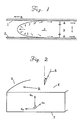
- Fig. 1 is a schematic diagram showing the behavior of molten resin in the mold cavity.
- Fig. 2 is a schematic representation to explain the refractive indexes n z , n x , and n y .
- a problem encountered in the optical high-density data recording medium designed to record and retrieve submicronsized data spots by means of a laser beam passing through a transparent substrate is a higher value of the birefringence of the transparent substrate.
- a recording medium having a high value of birefringence has such a low CN ratio (carrier-to-noise ratio) that it is of no practical use, particularly in the case of recording medium such as magneto-optical recording medium which is designed such that the reading of data is accomplished by detecting the change of the plane of polarization which is as small as 0.1 to 0.3 degrees.
- the transparent substrate should preferably be produced by injection molding from polycarbonate resin because of its low cost and its resistance to change by water absorption. Polycarbonate resin, however, has a disadvantage that the birefringence is high.
- the present inventors already disclosed that it is possible to greatly reduce the birefringence of the injection-molded substrate of polycarbonate by improving the molding conditions (Japanese Patent Application No. 12565-1984 or Japanese Patent Laid-open No. 155424/1985).
- Japanese Patent Application No. 12565-1984 or Japanese Patent Laid-open No. 155424/1985 In their continued researches, they found that the birefringence of the plastic substrate takes place not only in the direction parallel to the flat surface of the substrate (as believed previously) but also in the direction perpendicular to the flat surface, and that the birefringence in the latter direction strongly affects the CN ratio.
- the linearly polarized light is sent perpendicularly to the surface of the substrate and consequently the birefringence in the direction perpendicular to the surface of the substrate is not observed.
- the linearly polarized light is sent aslant (say 30°) with respect to the surface of the substrate, the transmitted light emerges from the crossed nicols. This phenomena cannot be explained on the hypothesis that there is the birefringence only in the direction parallel to the surface of the substrate; but it can be explained if an assumption is made that there is the birefringence also in the direction perpendicular to the surface of the substrate.
- the substrate made of polycarbonate resin has the optical anisotropism characterized by the refractive index n z in the direction perpendicular to the surface of the substrate and the refractlve indexes n x and n y parallel to the surface of the substrate.
- the absolute value of the difference between n x and n y is almost equal to 0; but the absolute values of the difference between n z and n x and between n z and n y are not equal to 0.
- the absolute values ranges from 0.0005 to 0.0006. This means that in the case of a 1.2 mm thick optical disk there occurs a retardation of 600-780 nm in the sectional direction.
- the polycarbonate substrate has the same optical anisotropism as the biaxial crystal has. It is apparent, however, that the optical anisotropism is attributable to the orientation of resin molecules that takes place in the mold cavity.
- Fig. 1 schematically shows the behavior of molten resin in the mold cavity.
- the molten resin 3 receives the shear stress in the radially inward direction from the mold surfaces 1 and 2 and the radially outward force exerted by the injection pressure. Therefore, the molten resin receives three forces along the thickness direction of the mold cavity that bring about orientation in the radialy inward direction, in the thickness direction, and in the radially inward direction simultaneously.
- the present inventors hypothesized that it would be necessary to control the orientation in the above-mentioned region B in order to lower the high birefringence which is one of the causes that aggravate the CN ratio of a polycarbonate resin substrate. And they carried out a series of experiments based on the hypothesis to complete the present invention.
- the disk substrate of the present invention which has specific refractive indexes had not existed before the present disclosure, because it was impossible to determine the effect of the refractive index n z in the direction perpendicular to the surface of the substrate so long as the birefringence was measured by the conventional method, i.e., by sending the linearly polarized light perpendicularly to the surface of the substrate.
- a recording medium for the optical high-density data storage and retrieval system designed to record and/or read data by means of an incident laser beam passing through a flat transparent plastic substrate, characterized in that the absolute values of the difference between the refractive index (n z ) in the direction perpendicular to the flat surface of the transparent plastic substrate and the refractive indexes (n x ) and (n y ) in the direction parallel to the flat surface, that is,
- are smaller than 4 ⁇ 10 ⁇ 4.
- the above-mentioned optical high-density data recording/retrieving system per se is known well.
- the system is designed to record and retrieve data by using a laser beam as thin as about 1 ⁇ m.
- a laser beam as thin as about 1 ⁇ m.
- the data are written in the form of pits on one side of the transparent plastic substrate when the substrate is molded, or the data are written by the user after the substrate has been molded. In the latter case, data are written on the Te-based DRAW film or the TbFeCo-based E-DRAW film formed on the plastic substrate with or without track grooves or preformatted pits.
- the laser beam for writing and reading the data is sent through the transparent plastic substrate (So-called back-reading system).
- the recording medium of the invention can also be applied to the so-called front-reading system.
- the recording medium is supported on a proper support and the laser beam is sent through the transparent plastic substrate of the invention arranged above the recording medium.
- the transparent plastic substrate it is necessary that the transparent plastic substrate have as small birefringence as possible.
- the refractive index n z in the direction perpendicular to the surface of the plastic substrate will be examined in the following. It is assumed that the transparent plastic substrate 5 has refractive indexes in three directions as show in Fig. 2 . They are refractive indexes n x and n y in the directions parallel to the flat surfaces 6 and 7 of the substrate and perpendicular to each other, and refractive index n z in the direction perpendicular to the flat surfaces 6 and 7.
- the birefringence attributable to n z was not measured by the conventional method, because the linearly polarized light was sent perpendicularly to the flat surfaces 6 and 7 to measure the birefringence.
- the present inventors observed the n z by sending the linearly polarized light 8 aslant (at an incident angle ( ⁇ ) of 30°, for example) with respect to the flat surface 6.
- the measuring method is not explained in detail because it is the same as the conventional one except that the incident angle is inclined through 30° with respect to the substrate.
- the point is that the linearly polarized light is sent through the substrate at an incident angle of 30° and the intensity of the transmitted light is measured under crossed nicols.
- n x equals n y in most cases.
- the absolute values /n z -n x / and /n z -n y / are much much greater than the value of birefringence which has been believed in the past. These values are greater than 0.0005 in the case of substrates produced by the conventional injection molding method. If a magneto-optical recording film is formed on such a substrate, the resulting magneto-optical disk has a CN ratio of about 48 dB.
- the CN ratio of the optical disk is increased to 51 dB if an magneto-optical recording film is formed on the substrate of the present invention which has the values /n z -n x / and /n z -n y / smaller than 0.0004. It is considered that the increase of CN ratio is attributable to the increase of kerr rotational angle ⁇ k , i.e. an angle of rotation of laser beam passing through a magnetic field, and the decrease of noise level.
- the present invention there is provided in the second place a process for producing the recording medium having the above mentioned features.
- an improved process for producing a recording medium for the optical high-density data storage and retrieval system by holding a flat transparent plastic substrate through injection molding of a molten resin into a flat mold cavity made up of a pair of split molds and arranging on at least one side of the thus formed transparent plastic substrate a data layer to record and/or retrieve data by means of an incident laser beam passing through the transparent plastic substrate, wherein said improvement comprises decreasing or increasing the clamping pressure and/or holding pressure in a portion of the pressure-holding stage after the injection and filling stage of a molten resin into the mold cavity in order to release pressure from or apply pressure to the resin filled in the mold cavity so that the absolute values of the difference between the refractive index (n z ) in the direction perpendicular to the flat surface of the transparent plastic substrate and the refractive indexes (n x ) and (n y ) in the direction parallel to
- the resin that can be used for the process of the invention includes any resin that exhibits the anisotropism of refractive index as mentioned above. Preferable among them is polycarbonate resin, which has other advantageous features in addition to the anisotrospism.
- the mold cavity used for the process has a dimension which varies according to the disk to be produced. The diameter is from about 3 cm to about 30 cm, and the thickness is from 1 mm to 2 mm, usually 1.2 mm.
- the molding machine is properly selected according to the dimensions of the disk. The molding operation is performed under the ordinary molding conditions for disk molding, except the special operation in the pressure-holding stage.
- the temperature of the injection cylinder is usually 300-400°C
- the mold temperature is about 90°C
- the injection speed of resin into the cavity is 10-500 ml/sec.
- the process for producing the recording medium is characterized by decreasing or increasing the clamping pressure and/or holding pressure in at least a portion of the pressure-holding stage after the injection and filling stage of a molten resin into the mold cavity in order to release pressure from or apply pressure to the resin filled in the mold cavity.
- the selection of pressure release or pressure application should be properly made according to need.
- Pressure decrease is selected in such cases that a relief pattern of a stamper can be transferred onto a disk surface even when the pressure is decreased.
- Pressure increase is selected when the pattern cannot be transferred under the condition of reduced pressure. Whichever might be selected, the object is to relieve or disperse the orientation of the resin in the direction perpendicular to the surface as shown in Fig. 1, i.e. to destroy orientation of polymer chains.
- the pressure release or pressure application be made at least in a portion of the pressure holding stage. In actual operation, it should be accomplished in the period starting immediately after the molten resin has been filled in the mold cavity by the injection stage which takes 1-2 seconds, and ending when the mold opening stage begins.
- the timing for pressure release or pressure application is properly selected in consideration of transferability of a relief pattern from a mold or stamper surface to a molded disk surface which in practice is determined by measuring a shape or profile of the molded disk. In other words, the timing is after the surface of the molten resin filled in the cavity has begun to solidify on contact with the cooled mold, but before the inside of the molten resin is not yet cooled.
- the pressure release or pressure application should preferably be performed while the region B (in Fig. 1) is not yet solidified.
- the pressure release to lower the holding pressure may be accomplished after the completion of injection by decreasing the clamping force to a great extent or to nearly zero or by retracting the injection screw or by the combination thereof.
- the pressure application may be accomplished by increasing the holding pressure again.
- the pressure release or pressure application should be accomplished before the resin in the region B substantially solidifies.
- the pressure release and pressure application may be accomplished consecutively. As well, cases are possible that pressure is increased and decreased consecutively or successively (repeatedly). When both pressure decrease and increase are applied, pressure ranges may be different from the case of only one of pressure decrease or increase.
- the above mentioned steps partly alleviate the molding strain and cooling strain, making it possible to produce the disk substrate having small values /n z -n x / and /n z -n y /.
- a disk substrate was produced from polycarbonate of 2,2-bis(4-hydroxydiphenyl)propane having an average molecular weight of 15,000 using a Dynamelter injection molding machine made by Meiki Seisakusho.
- the mold cavity measures 300 mm in diameter and 1.2 mm thick.
- To one side of the cavity is attached a stamper having 1.6- ⁇ m pitch track grooves.
- the injection cylinder temperature was 340°C
- the mold temperature was 90°C
- the injection speed was 120 ml/ sec
- the injection time was about 1.5 sec.
- the pressure release was started 0.2 seconds after the completion of injection, and it lasted for 5 sec until the clamping force decreased linearly from 200 tons to zero. Ten seconds later, the mold was opened and the disk substrate was demolded.
- the refractive indexes of the thus obtained disk was measured by sending a linearly polarized light at an incident angle of 30° with respect to the surface of the disk.
- the value of /n z -n y / was 0.0003, which is equivalent to 360 nm in terms of retardation.
- On this disk substrate was formed a magneto-optical recording layer of Gd 0.12 Tb 0.12 Fe 0.76 by sputtering in the usual way.
- the resulting optomagnetic disk was found to have a CN ratio of 51 dB.
- Example 2 The same procedure as in Example 1 was repeated except that the step of pressure release was replaced by the step of pressure application.
- the pressure application was started 0.2 seconds after the completion of injection, and it lasted for 5 sec until the clamping force increased linearly from 150 tons to 250 tons.
- the value of /n z -n y / was 0.0004.
- On this substrate was formed a magneto-optical recording layer.
- the resulting magneto-optical disk was found to have a CN ratio of 50 dB.
Landscapes
- Engineering & Computer Science (AREA)
- Manufacturing & Machinery (AREA)
- Mechanical Engineering (AREA)
- Injection Moulding Of Plastics Or The Like (AREA)
- Optical Record Carriers And Manufacture Thereof (AREA)
- Polyesters Or Polycarbonates (AREA)
- Manufacturing Optical Record Carriers (AREA)
Claims (14)
Applications Claiming Priority (2)
| Application Number | Priority Date | Filing Date | Title |
|---|---|---|---|
| JP45900/86 | 1986-03-03 | ||
| JP61045900A JPS62204451A (ja) | 1986-03-03 | 1986-03-03 | 光デイスク用プラスチツク基板とその製法 |
Publications (3)
| Publication Number | Publication Date |
|---|---|
| EP0235800A2 EP0235800A2 (de) | 1987-09-09 |
| EP0235800A3 EP0235800A3 (en) | 1989-03-29 |
| EP0235800B1 true EP0235800B1 (de) | 1991-06-26 |
Family
ID=12732116
Family Applications (1)
| Application Number | Title | Priority Date | Filing Date |
|---|---|---|---|
| EP87103007A Expired EP0235800B1 (de) | 1986-03-03 | 1987-03-03 | Kunststoffsubstrat für optische Platte und Verfahren zu seiner Herstellung |
Country Status (4)
| Country | Link |
|---|---|
| US (2) | US4841501A (de) |
| EP (1) | EP0235800B1 (de) |
| JP (1) | JPS62204451A (de) |
| DE (1) | DE3770955D1 (de) |
Families Citing this family (20)
| Publication number | Priority date | Publication date | Assignee | Title |
|---|---|---|---|---|
| JP2519213B2 (ja) * | 1986-07-31 | 1996-07-31 | シャープ株式会社 | 光磁気デイスク板の製造方法 |
| JPH0675888B2 (ja) * | 1986-11-28 | 1994-09-28 | ソニー株式会社 | デイスクの射出成形方法 |
| JPH078514B2 (ja) * | 1988-04-18 | 1995-02-01 | ダイセル化学工業株式会社 | 光ディスク用プラスチック基板の射出成形法 |
| JP2906349B2 (ja) * | 1989-11-01 | 1999-06-21 | 住友重機械工業株式会社 | 光ディスク基板の製造方法 |
| US5696755A (en) * | 1992-11-04 | 1997-12-09 | Storage Technology Corporation | System for minimizing the effects of scratches on recording media |
| JPH06243523A (ja) * | 1993-02-16 | 1994-09-02 | Canon Inc | 光磁気ディスクおよび光磁気ディスクシステム |
| JP3512595B2 (ja) * | 1996-11-07 | 2004-03-29 | 株式会社リコー | プラスチック成形品の成形方法およびプラスチック成形品の成形用金型 |
| JP3116986B2 (ja) * | 1994-04-08 | 2000-12-11 | 三菱化学株式会社 | 光学的情報記録用媒体およびその記録再生方法 |
| US5683630A (en) * | 1994-06-20 | 1997-11-04 | Matsushita Electric Industrial Co., Ltd. | Process for making optical disk substrates |
| JP3385491B2 (ja) * | 1994-06-21 | 2003-03-10 | コニカ株式会社 | 射出成形方法 |
| JPH08187757A (ja) * | 1995-01-10 | 1996-07-23 | Meiki Co Ltd | ディスク基板の成形方法 |
| US5635114A (en) | 1995-08-14 | 1997-06-03 | Hong Gilbert H | Method of making thin film optical storage media |
| US7179551B2 (en) | 1999-02-12 | 2007-02-20 | General Electric Company | Poly(arylene ether) data storage media |
| KR100755089B1 (ko) | 1999-02-12 | 2007-09-03 | 제너럴 일렉트릭 캄파니 | 저장 매체, 기판 제조 방법, 데이터 검색 방법, 엠보싱 방법 및 데이터 저장 매체 형성 방법 |
| WO2002085537A2 (en) * | 2001-04-19 | 2002-10-31 | General Electric Company | Spin coating process |
| DE10141858B4 (de) * | 2001-08-27 | 2010-06-17 | Kraussmaffei Technologies Gmbh | Verfahren und Vorrichtung zum Herstellen flächenartiger Kunststoff-Formteile, insbesondere Kunststoffscheiben |
| US20100170566A1 (en) * | 2009-01-06 | 2010-07-08 | Arthur Don Harmala | Apparatus and method for manufacturing polymer solar cells |
| US8202407B1 (en) | 2009-01-06 | 2012-06-19 | Arthur Don Harmala | Apparatus and method for manufacturing polycarbonate solar cells |
| JP6209965B2 (ja) * | 2013-12-20 | 2017-10-11 | 日本ゼオン株式会社 | プラスチック製透過型光学素子成形方法 |
| CN106696192B (zh) * | 2016-12-23 | 2018-11-09 | 河南工程学院 | 微注塑压缩模具 |
Family Cites Families (18)
| Publication number | Priority date | Publication date | Assignee | Title |
|---|---|---|---|---|
| US3556662A (en) * | 1968-05-03 | 1971-01-19 | Us Navy | Device for determining birefringence |
| US4185955A (en) * | 1977-10-31 | 1980-01-29 | Mca Disco-Vision, Inc. | Apparatus for replicating centrally apertured video disc records |
| DE2966968D1 (en) * | 1978-08-28 | 1984-06-14 | Discovision Ass | Method for moulding a videodisc composition |
| JPS5597929A (en) * | 1979-01-19 | 1980-07-25 | Matsushita Electric Ind Co Ltd | Production of flat plate-shaped body |
| US4397805A (en) * | 1979-04-18 | 1983-08-09 | Discovision Associates | Method for making a video disc |
| JPS56145535A (en) * | 1980-04-15 | 1981-11-12 | Matsushita Electric Ind Co Ltd | Disc for optical recording |
| JPS5727451A (en) * | 1980-07-23 | 1982-02-13 | Sharp Corp | Magnetooptic storage element |
| JPS5938944A (ja) * | 1982-08-26 | 1984-03-03 | Toshiba Corp | 光学式情報記憶媒体 |
| JPS59113534A (ja) * | 1982-12-20 | 1984-06-30 | Canon Inc | 光学記録媒体 |
| JPS60219028A (ja) * | 1984-04-16 | 1985-11-01 | Mitsui Toatsu Chem Inc | コンパクトデイスク用熱可塑性樹脂シ−ト |
| AT381063B (de) * | 1983-09-28 | 1986-08-25 | Npo Plastik | Verfahren zum herstellen von kunststoffteilen |
| JPS60155424A (ja) * | 1984-01-26 | 1985-08-15 | Daicel Chem Ind Ltd | 大径のポリカ−ボネ−ト製光デイスク基板およびその製造法 |
| JPS615913A (ja) * | 1984-06-20 | 1986-01-11 | Sumitomo Bakelite Co Ltd | 円板状記録媒体基板成形装置 |
| JPH0684031B2 (ja) * | 1984-08-16 | 1994-10-26 | 三菱マテリアル株式会社 | 射出成形方法 |
| JPS6180640A (ja) * | 1984-09-28 | 1986-04-24 | Canon Inc | 光学的記録媒体 |
| JPS6195919A (ja) * | 1984-10-18 | 1986-05-14 | Sony Corp | 射出成形機 |
| KR900004755B1 (ko) * | 1985-06-14 | 1990-07-05 | 마쯔시다덴기산교 가부시기가이샤 | 광 디스크 |
| US4828769A (en) * | 1986-05-05 | 1989-05-09 | Galic/Maus Ventures | Method for injection molding articles |
-
1986
- 1986-03-03 JP JP61045900A patent/JPS62204451A/ja active Granted
-
1987
- 1987-02-27 US US07/019,720 patent/US4841501A/en not_active Expired - Fee Related
- 1987-03-03 DE DE8787103007T patent/DE3770955D1/de not_active Expired - Lifetime
- 1987-03-03 EP EP87103007A patent/EP0235800B1/de not_active Expired
-
1989
- 1989-04-14 US US07/338,834 patent/US4986938A/en not_active Expired - Fee Related
Also Published As
| Publication number | Publication date |
|---|---|
| JPH0568778B2 (de) | 1993-09-29 |
| JPS62204451A (ja) | 1987-09-09 |
| EP0235800A2 (de) | 1987-09-09 |
| DE3770955D1 (de) | 1991-08-01 |
| US4986938A (en) | 1991-01-22 |
| EP0235800A3 (en) | 1989-03-29 |
| US4841501A (en) | 1989-06-20 |
Similar Documents
| Publication | Publication Date | Title |
|---|---|---|
| EP0235800B1 (de) | Kunststoffsubstrat für optische Platte und Verfahren zu seiner Herstellung | |
| BR8704985A (pt) | Substrato de material polimerico rigido e circular e discos para o armazenamento de informacoes e discos oticos | |
| US4961884A (en) | Process for producing substrate of optical disc | |
| JPH078514B2 (ja) | 光ディスク用プラスチック基板の射出成形法 | |
| EP0280028B1 (de) | Optische Informationsplatte | |
| EP0474050B1 (de) | Magneto-optische Scheibe | |
| JPH0579011B2 (de) | ||
| US6325950B1 (en) | Method for producing optical disc substrates | |
| JPS62246708A (ja) | 光デイスク用プラスチツク基板の射出成形法 | |
| USRE37719E1 (en) | Optical data recording system and method of production of recording medium | |
| JP2685092B2 (ja) | 光情報記録媒体及びその製造方法 | |
| Umezawa et al. | The Influence of Adjacent Preformat Pits on Magneto-Optical Signals | |
| JP3304377B2 (ja) | 光ディスク | |
| JPH0579010B2 (de) | ||
| JP2500146B2 (ja) | 光情報記録媒体の製造方法 | |
| RU2191695C2 (ru) | Способ изготовления носителя для записи информации | |
| JP2650839B2 (ja) | 光情報記録媒体 | |
| JPH0579009B2 (de) | ||
| JP3072736B2 (ja) | 光ディスク基板成形装置 | |
| JPH03119534A (ja) | 情報記録担体とその製造方法及びその成形金型 | |
| JP2001058341A (ja) | 光ディスク基板成形金型および光ディスク基板 | |
| JP2685092C (de) | ||
| JP2500146C (de) | ||
| JPH07192321A (ja) | 光ディスク用プラスチック基板の製造方法 | |
| JPH08142144A (ja) | 複屈折に優れた光ディスク成形基板の製造方法及びこの成形基板を用いて得られる光ディスク |
Legal Events
| Date | Code | Title | Description |
|---|---|---|---|
| PUAI | Public reference made under article 153(3) epc to a published international application that has entered the european phase |
Free format text: ORIGINAL CODE: 0009012 |
|
| AK | Designated contracting states |
Kind code of ref document: A2 Designated state(s): DE FR GB NL |
|
| 17P | Request for examination filed |
Effective date: 19871026 |
|
| PUAL | Search report despatched |
Free format text: ORIGINAL CODE: 0009013 |
|
| AK | Designated contracting states |
Kind code of ref document: A3 Designated state(s): DE FR GB NL |
|
| 17Q | First examination report despatched |
Effective date: 19900808 |
|
| GRAA | (expected) grant |
Free format text: ORIGINAL CODE: 0009210 |
|
| AK | Designated contracting states |
Kind code of ref document: B1 Designated state(s): DE FR GB NL |
|
| ET | Fr: translation filed | ||
| REF | Corresponds to: |
Ref document number: 3770955 Country of ref document: DE Date of ref document: 19910801 |
|
| PLBI | Opposition filed |
Free format text: ORIGINAL CODE: 0009260 |
|
| 26 | Opposition filed |
Opponent name: N.V. PHILIPS GLOELAMPENFABRIEKEN Effective date: 19920326 |
|
| NLR1 | Nl: opposition has been filed with the epo |
Opponent name: N.V. PHILIPS GLOEILAMPENFABRIEKEN. |
|
| REG | Reference to a national code |
Ref country code: GB Ref legal event code: 732E |
|
| REG | Reference to a national code |
Ref country code: FR Ref legal event code: TP |
|
| NLS | Nl: assignments of ep-patents |
Owner name: OLYMPUS OPTICAL CO., LTD.;DAICEL CHEMICAL INDUSTRI |
|
| RDAH | Patent revoked |
Free format text: ORIGINAL CODE: EPIDOS REVO |
|
| APAC | Appeal dossier modified |
Free format text: ORIGINAL CODE: EPIDOS NOAPO |
|
| APAE | Appeal reference modified |
Free format text: ORIGINAL CODE: EPIDOS REFNO |
|
| PGFP | Annual fee paid to national office [announced via postgrant information from national office to epo] |
Ref country code: GB Payment date: 19990304 Year of fee payment: 13 |
|
| PGFP | Annual fee paid to national office [announced via postgrant information from national office to epo] |
Ref country code: FR Payment date: 19990309 Year of fee payment: 13 |
|
| PGFP | Annual fee paid to national office [announced via postgrant information from national office to epo] |
Ref country code: DE Payment date: 19990315 Year of fee payment: 13 |
|
| PGFP | Annual fee paid to national office [announced via postgrant information from national office to epo] |
Ref country code: NL Payment date: 19990329 Year of fee payment: 13 |
|
| PG25 | Lapsed in a contracting state [announced via postgrant information from national office to epo] |
Ref country code: GB Free format text: LAPSE BECAUSE OF NON-PAYMENT OF DUE FEES Effective date: 20000303 |
|
| PG25 | Lapsed in a contracting state [announced via postgrant information from national office to epo] |
Ref country code: NL Free format text: LAPSE BECAUSE OF NON-PAYMENT OF DUE FEES Effective date: 20001001 |
|
| APAC | Appeal dossier modified |
Free format text: ORIGINAL CODE: EPIDOS NOAPO |
|
| GBPC | Gb: european patent ceased through non-payment of renewal fee |
Effective date: 20000303 |
|
| RDAG | Patent revoked |
Free format text: ORIGINAL CODE: 0009271 |
|
| STAA | Information on the status of an ep patent application or granted ep patent |
Free format text: STATUS: PATENT REVOKED |
|
| NLV4 | Nl: lapsed or anulled due to non-payment of the annual fee |
Effective date: 20001001 |
|
| 27W | Patent revoked |
Effective date: 20001018 |
|
| REG | Reference to a national code |
Ref country code: FR Ref legal event code: ST |
|
| APAH | Appeal reference modified |
Free format text: ORIGINAL CODE: EPIDOSCREFNO |