EP0231908A2 - Procédé et appareil pour réactions de saponification - Google Patents
Procédé et appareil pour réactions de saponification Download PDFInfo
- Publication number
- EP0231908A2 EP0231908A2 EP87101320A EP87101320A EP0231908A2 EP 0231908 A2 EP0231908 A2 EP 0231908A2 EP 87101320 A EP87101320 A EP 87101320A EP 87101320 A EP87101320 A EP 87101320A EP 0231908 A2 EP0231908 A2 EP 0231908A2
- Authority
- EP
- European Patent Office
- Prior art keywords
- conduit
- vessel
- openings
- acid
- recirculating
- Prior art date
- Legal status (The legal status is an assumption and is not a legal conclusion. Google has not performed a legal analysis and makes no representation as to the accuracy of the status listed.)
- Withdrawn
Links
- 238000000034 method Methods 0.000 title claims abstract description 26
- 238000007127 saponification reaction Methods 0.000 title claims abstract description 12
- 238000006243 chemical reaction Methods 0.000 claims abstract description 22
- 230000035484 reaction time Effects 0.000 claims abstract description 9
- 238000003860 storage Methods 0.000 claims abstract description 9
- 230000003134 recirculating effect Effects 0.000 claims description 29
- 239000007788 liquid Substances 0.000 claims description 21
- 239000000344 soap Substances 0.000 claims description 13
- 239000000126 substance Substances 0.000 claims description 11
- 239000003784 tall oil Substances 0.000 claims description 8
- KWYUFKZDYYNOTN-UHFFFAOYSA-M Potassium hydroxide Chemical compound [OH-].[K+] KWYUFKZDYYNOTN-UHFFFAOYSA-M 0.000 claims description 7
- HEMHJVSKTPXQMS-UHFFFAOYSA-M Sodium hydroxide Chemical compound [OH-].[Na+] HEMHJVSKTPXQMS-UHFFFAOYSA-M 0.000 claims description 6
- 239000002994 raw material Substances 0.000 claims description 6
- OYHQOLUKZRVURQ-NTGFUMLPSA-N (9Z,12Z)-9,10,12,13-tetratritiooctadeca-9,12-dienoic acid Chemical compound C(CCCCCCC\C(=C(/C\C(=C(/CCCCC)\[3H])\[3H])\[3H])\[3H])(=O)O OYHQOLUKZRVURQ-NTGFUMLPSA-N 0.000 claims description 4
- ZQPPMHVWECSIRJ-UHFFFAOYSA-N Oleic acid Natural products CCCCCCCCC=CCCCCCCCC(O)=O ZQPPMHVWECSIRJ-UHFFFAOYSA-N 0.000 claims description 4
- QXJSBBXBKPUZAA-UHFFFAOYSA-N isooleic acid Natural products CCCCCCCC=CCCCCCCCCC(O)=O QXJSBBXBKPUZAA-UHFFFAOYSA-N 0.000 claims description 4
- WRIDQFICGBMAFQ-UHFFFAOYSA-N (E)-8-Octadecenoic acid Natural products CCCCCCCCCC=CCCCCCCC(O)=O WRIDQFICGBMAFQ-UHFFFAOYSA-N 0.000 claims description 3
- LQJBNNIYVWPHFW-UHFFFAOYSA-N 20:1omega9c fatty acid Natural products CCCCCCCCCCC=CCCCCCCCC(O)=O LQJBNNIYVWPHFW-UHFFFAOYSA-N 0.000 claims description 3
- QSBYPNXLFMSGKH-UHFFFAOYSA-N 9-Heptadecensaeure Natural products CCCCCCCC=CCCCCCCCC(O)=O QSBYPNXLFMSGKH-UHFFFAOYSA-N 0.000 claims description 3
- IPCSVZSSVZVIGE-UHFFFAOYSA-N hexadecanoic acid Chemical compound CCCCCCCCCCCCCCCC(O)=O IPCSVZSSVZVIGE-UHFFFAOYSA-N 0.000 claims description 3
- FUZZWVXGSFPDMH-UHFFFAOYSA-N hexanoic acid Chemical compound CCCCCC(O)=O FUZZWVXGSFPDMH-UHFFFAOYSA-N 0.000 claims description 3
- WWZKQHOCKIZLMA-UHFFFAOYSA-N octanoic acid Chemical compound CCCCCCCC(O)=O WWZKQHOCKIZLMA-UHFFFAOYSA-N 0.000 claims description 3
- 239000003921 oil Substances 0.000 claims description 3
- GSEJCLTVZPLZKY-UHFFFAOYSA-N Triethanolamine Chemical compound OCCN(CCO)CCO GSEJCLTVZPLZKY-UHFFFAOYSA-N 0.000 claims description 2
- 235000014113 dietary fatty acids Nutrition 0.000 claims description 2
- 229930195729 fatty acid Natural products 0.000 claims description 2
- 239000000194 fatty acid Substances 0.000 claims description 2
- 150000004665 fatty acids Chemical class 0.000 claims description 2
- 239000011541 reaction mixture Substances 0.000 claims description 2
- FERIUCNNQQJTOY-UHFFFAOYSA-N Butyric acid Chemical compound CCCC(O)=O FERIUCNNQQJTOY-UHFFFAOYSA-N 0.000 claims 2
- POULHZVOKOAJMA-UHFFFAOYSA-N dodecanoic acid Chemical compound CCCCCCCCCCCC(O)=O POULHZVOKOAJMA-UHFFFAOYSA-N 0.000 claims 2
- 239000011344 liquid material Substances 0.000 claims 2
- FBUKVWPVBMHYJY-UHFFFAOYSA-N nonanoic acid Chemical compound CCCCCCCCC(O)=O FBUKVWPVBMHYJY-UHFFFAOYSA-N 0.000 claims 2
- 235000019198 oils Nutrition 0.000 claims 2
- HZAXFHJVJLSVMW-UHFFFAOYSA-N 2-Aminoethan-1-ol Chemical compound NCCO HZAXFHJVJLSVMW-UHFFFAOYSA-N 0.000 claims 1
- 239000005635 Caprylic acid (CAS 124-07-2) Substances 0.000 claims 1
- 239000005639 Lauric acid Substances 0.000 claims 1
- 239000005642 Oleic acid Substances 0.000 claims 1
- 235000021314 Palmitic acid Nutrition 0.000 claims 1
- 235000021355 Stearic acid Nutrition 0.000 claims 1
- 239000003513 alkali Substances 0.000 claims 1
- 239000003240 coconut oil Substances 0.000 claims 1
- 235000019864 coconut oil Nutrition 0.000 claims 1
- ZBCBWPMODOFKDW-UHFFFAOYSA-N diethanolamine Chemical compound OCCNCCO ZBCBWPMODOFKDW-UHFFFAOYSA-N 0.000 claims 1
- ZQPPMHVWECSIRJ-MDZDMXLPSA-N elaidic acid Chemical compound CCCCCCCC\C=C\CCCCCCCC(O)=O ZQPPMHVWECSIRJ-MDZDMXLPSA-N 0.000 claims 1
- WQEPLUUGTLDZJY-UHFFFAOYSA-N n-Pentadecanoic acid Natural products CCCCCCCCCCCCCCC(O)=O WQEPLUUGTLDZJY-UHFFFAOYSA-N 0.000 claims 1
- QIQXTHQIDYTFRH-UHFFFAOYSA-N octadecanoic acid Chemical compound CCCCCCCCCCCCCCCCCC(O)=O QIQXTHQIDYTFRH-UHFFFAOYSA-N 0.000 claims 1
- OQCDKBAXFALNLD-UHFFFAOYSA-N octadecanoic acid Natural products CCCCCCCC(C)CCCCCCCCC(O)=O OQCDKBAXFALNLD-UHFFFAOYSA-N 0.000 claims 1
- 229960002446 octanoic acid Drugs 0.000 claims 1
- ZQPPMHVWECSIRJ-KTKRTIGZSA-N oleic acid Chemical compound CCCCCCCC\C=C/CCCCCCCC(O)=O ZQPPMHVWECSIRJ-KTKRTIGZSA-N 0.000 claims 1
- 235000021313 oleic acid Nutrition 0.000 claims 1
- 150000002889 oleic acids Chemical class 0.000 claims 1
- 239000008117 stearic acid Substances 0.000 claims 1
- TUNFSRHWOTWDNC-HKGQFRNVSA-N tetradecanoic acid Chemical compound CCCCCCCCCCCCC[14C](O)=O TUNFSRHWOTWDNC-HKGQFRNVSA-N 0.000 claims 1
- 239000000376 reactant Substances 0.000 abstract description 12
- 238000004064 recycling Methods 0.000 abstract description 3
- 238000001311 chemical methods and process Methods 0.000 abstract 1
- XLYOFNOQVPJJNP-UHFFFAOYSA-N water Substances O XLYOFNOQVPJJNP-UHFFFAOYSA-N 0.000 description 20
- 239000004615 ingredient Substances 0.000 description 18
- 238000004519 manufacturing process Methods 0.000 description 9
- 239000000047 product Substances 0.000 description 5
- 239000000203 mixture Substances 0.000 description 4
- KFZMGEQAYNKOFK-UHFFFAOYSA-N Isopropanol Chemical compound CC(C)O KFZMGEQAYNKOFK-UHFFFAOYSA-N 0.000 description 3
- 239000003518 caustics Substances 0.000 description 3
- 239000003599 detergent Substances 0.000 description 3
- 238000012163 sequencing technique Methods 0.000 description 3
- 239000002904 solvent Substances 0.000 description 3
- KCXVZYZYPLLWCC-UHFFFAOYSA-N EDTA Chemical compound OC(=O)CN(CC(O)=O)CCN(CC(O)=O)CC(O)=O KCXVZYZYPLLWCC-UHFFFAOYSA-N 0.000 description 2
- 241000196324 Embryophyta Species 0.000 description 2
- -1 butyric Chemical class 0.000 description 2
- 239000003085 diluting agent Substances 0.000 description 2
- 230000000694 effects Effects 0.000 description 2
- DKPFZGUDAPQIHT-UHFFFAOYSA-N Butyl acetate Natural products CCCCOC(C)=O DKPFZGUDAPQIHT-UHFFFAOYSA-N 0.000 description 1
- 235000013162 Cocos nucifera Nutrition 0.000 description 1
- 244000060011 Cocos nucifera Species 0.000 description 1
- 239000002253 acid Substances 0.000 description 1
- 239000000654 additive Substances 0.000 description 1
- 239000004599 antimicrobial Substances 0.000 description 1
- 235000013361 beverage Nutrition 0.000 description 1
- 238000004140 cleaning Methods 0.000 description 1
- 150000001875 compounds Chemical class 0.000 description 1
- 235000013365 dairy product Nutrition 0.000 description 1
- 238000010586 diagram Methods 0.000 description 1
- MTHSVFCYNBDYFN-UHFFFAOYSA-N diethylene glycol Chemical compound OCCOCCO MTHSVFCYNBDYFN-UHFFFAOYSA-N 0.000 description 1
- 239000000686 essence Substances 0.000 description 1
- 238000005886 esterification reaction Methods 0.000 description 1
- 235000013305 food Nutrition 0.000 description 1
- 230000005484 gravity Effects 0.000 description 1
- 239000008233 hard water Substances 0.000 description 1
- 150000002500 ions Chemical class 0.000 description 1
- 239000012263 liquid product Substances 0.000 description 1
- 239000000314 lubricant Substances 0.000 description 1
- 239000000463 material Substances 0.000 description 1
- 238000005259 measurement Methods 0.000 description 1
- 150000002888 oleic acid derivatives Chemical class 0.000 description 1
- 239000002304 perfume Substances 0.000 description 1
- 239000003755 preservative agent Substances 0.000 description 1
- 238000004886 process control Methods 0.000 description 1
- 239000008234 soft water Substances 0.000 description 1
- 239000010891 toxic waste Substances 0.000 description 1
- 239000002699 waste material Substances 0.000 description 1
- 238000005303 weighing Methods 0.000 description 1
Images


Classifications
-
- C—CHEMISTRY; METALLURGY
- C11—ANIMAL OR VEGETABLE OILS, FATS, FATTY SUBSTANCES OR WAXES; FATTY ACIDS THEREFROM; DETERGENTS; CANDLES
- C11D—DETERGENT COMPOSITIONS; USE OF SINGLE SUBSTANCES AS DETERGENTS; SOAP OR SOAP-MAKING; RESIN SOAPS; RECOVERY OF GLYCEROL
- C11D13/00—Making of soap or soap solutions in general; Apparatus therefor
-
- B—PERFORMING OPERATIONS; TRANSPORTING
- B01—PHYSICAL OR CHEMICAL PROCESSES OR APPARATUS IN GENERAL
- B01F—MIXING, e.g. DISSOLVING, EMULSIFYING OR DISPERSING
- B01F23/00—Mixing according to the phases to be mixed, e.g. dispersing or emulsifying
- B01F23/40—Mixing liquids with liquids; Emulsifying
- B01F23/49—Mixing systems, i.e. flow charts or diagrams
-
- B—PERFORMING OPERATIONS; TRANSPORTING
- B01—PHYSICAL OR CHEMICAL PROCESSES OR APPARATUS IN GENERAL
- B01J—CHEMICAL OR PHYSICAL PROCESSES, e.g. CATALYSIS OR COLLOID CHEMISTRY; THEIR RELEVANT APPARATUS
- B01J19/00—Chemical, physical or physico-chemical processes in general; Their relevant apparatus
- B01J19/0006—Controlling or regulating processes
-
- Y—GENERAL TAGGING OF NEW TECHNOLOGICAL DEVELOPMENTS; GENERAL TAGGING OF CROSS-SECTIONAL TECHNOLOGIES SPANNING OVER SEVERAL SECTIONS OF THE IPC; TECHNICAL SUBJECTS COVERED BY FORMER USPC CROSS-REFERENCE ART COLLECTIONS [XRACs] AND DIGESTS
- Y10—TECHNICAL SUBJECTS COVERED BY FORMER USPC
- Y10T—TECHNICAL SUBJECTS COVERED BY FORMER US CLASSIFICATION
- Y10T436/00—Chemistry: analytical and immunological testing
- Y10T436/12—Condition responsive control
Definitions
- This invention relates to a new and Improved process and apparatus for saponification reactions and the like, e.g. to produce liquid soaps, on a batch scale over a sufficiently short time Interval to effect a semicontinuous process.
- the reaction times are In the order of about 2 - 8 minutes, and reactor vessel capacities are of about 1 - 25 gallons, or greater.
- the chemical Industry manufactures a wide variety of liquid soaps at plant sites In large quantities for shipping in container cars, drums, etc.
- the containers are then returned to the site and refilled. in the case of drums, they are usually washed prior to return, which creates a waste disposal problem.
- the weight of water diluent In the liquid soap represents a transportation expense.
- Today, the manufacture of liquid soaps used In Industry no longer poses a manufacturing problem from the chemical standpoint. The greater problem Is posed In transportation of chemically toxic wastes, and In use of reactors which are economically effective in both large and small scale manufacture of the product.
- a process and apparatus Is provided for the batch manufacture on a seml- continuous basis for saponfication reactions and the like.
- the reactions produce liquid products during a reaction time which varies from about 2 - 8 minutes.
- the ingredients are added sequentially In weighed amounts to water In the reactor, and the mixture of water and Ingredients are recycled, usually continuously, to ensure adequate mixing during a predetermined reaction time set for each ingredient.
- the recycling operation Is stopped and the liquid reactant product is fed to storage; the process is then repeated. Since the process is carried out a large number of times dally, It is preferred to employ a microprocessor to control valve on-off times to enable sequencing of reactant addition and reaction times. This reduces the possibility of operator errors and also ensures product uniformity.
- Various techniques may be used to obtain an accurate feed of reactants and include the use of a load cell, pump rates (rpm), timed volume feed, etc. It Is to be understood, however, that the equipment can also be controlled manually, using suitable valves and pumps well known to the art.
- the microprocessor which Is the preferred method of controlling the equipment, can be readlly selected from commercially available units by those skilled In this art. For example, using an STD bus, a main processor board, an STD bus card to control Inputs and outputs for the valves, pumps, and switches used with the equipment, and another STD bus card to read the load cell used with one embodiment of the equipment, are commercially readlly available, e.g. from Prolog, Inc., or Computer Dynamics Company.
- the operating program which Is stored on the main processor board, can readily be prepared by one skilled In this art to operate the equipment for any process to be run In accordance with the teachings of the present Invention.
- Typical raw materials for saponification reactions include: tall I oll, coconut oll, olelc acid, linoleic acid, saponiflable olis containing liquid oleic and linoleic acid, and cracked oils.
- Other base chemicals include fatty acids such as butyric, caproic, caprylic, undecanoic, capric, nonanoic, lauric, myristic, palmitic, stearic, elaldlc, and mixtures thereof.
- Alkalis suitable for the saponification reaction include NaOH, KOH, and the mono, dl, and triethanolamines.
- Reaction temperatures usually vary from about 120°F - 140°F, however, the maximum temperature limits vary from about 70°F to about 200°F. These temperatures are achieved partly by the use of hot water and partly by the exothermic nature of the reaction.
- the usual concentrations of ingredients are about 5:1 - 6:1 of saponifiable raw material/caustic, where the saponification number varies from about 175 - 280.
- the amount of water used Is at least 60% of the total weight of ingredients, and typically 75% - 80% by weight of the ingredient concentration.
- Saponifiable olis e.g., tall oil, may be employed as a 100% concentrated liquid, and the caustic is added as a 45% - 50% solution.
- Additives such as chelates, EDTA and detergents may be used to reduce the effect of hard water Ions.
- Solvents such as isopropyl alcohol, glycol ether and butyl acetate are useful as solvents and viscosity thinners.
- Reactor vessel sizes of about 1 - 25 gallons are suitable for most reactions, and the only practical upper limit on reactor size Is that imposed by the economics of a large size plant. It will be appreciated that small size reactors of say 1-2 gallons are suitable for use In such diverse areas as dairies, laundries, restaurants, hotels, etc., where the raw material economics and process costs are counterbalanced by the cost of delivered liquid soap.
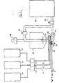
- FIG. 1 One embodiment of the apparatus of this invention is shown In FIG. 1, and comprises a cone-shaped reactor vessel 10 fed from a supply tank 11 containing water 12, and from reactor tanks 13, 14 and 15.
- a cone-shaped reactor vessel 10 fed from a supply tank 11 containing water 12, and from reactor tanks 13, 14 and 15.
- water Prior to commencement of the reaction, water Is gravity fed and measured Into the reactor throught valve 19 and line 16, followed In sequence by the other reactants.
- the material to be reacted, e.g. tall oil, from tank 13 Is then fed through line 17 by pump 18, to produce a measured, stoichiometric amount of reactant, and then fed through an Inlet feed pipe 20 Into the reactor vessel 10.
- the feed pipe 20 has two sets of spaced openings 21 and 22 and a baffle plate 23 between the two sets of openings to direct the flow of water and reactants toward the sidewall of the vessel for improved circulation and mixing.
- Each set of openings Is preferably positioned around the circumference of the conduit, more
- a recirculating pump 30 recirculates the mixture of water and the reactant from tank 13 from the bottom of the. reactor vessel 10 and through a recirculation valve 30a to an Intermediate level of reactor vessel 10, usually Just (e.g. 2 Inches) below the liquid level of reactor vessel 10, until adequate mixing has occurred.
- a measured quantity of caustic such as KOH Is fed from tank 14 through line 31 by pump 32, and pumped Into the reactor vessel 10.
- Mixing by means of the recirculating pump 30 is continued.
- a measured quantity of other components such as EDTA, chelates, detergents, solvents, thinners, etc., in tank 15 (or additional tanks, If necessary) are pumped through line 33 by pump 34 to the reactor vessel 10.
- Mixing and reacting by means of recirculation pump 30 is continued.
- the recirculation valve 30a is switched from the reactor vessel 10 to a storage tank 35 through line 36.
- the liquid soap or other product which has been formed In the reactor vessel Is then pumped out of the reactor by pump 30 through line 36 and Into storage tank 35, or other containers, etc., for use.
- the heat of reaction which has been transferred from the reactor to the storage tank can be removed for use in the building.
- Reactor vessel 40 Is shown with conduit 41 having lower entry ports 42, 43 and 44, which lead from supply tanks 45, 46 and 47.
- Pumps 48, 49 and 50 sequentially pump the reactants from their respective supply tanks through lines 51, 52 and 53 to the lower entry ports 42, 43 and 44.
- Water is separately fed from a supply source (e.g., a water line) through Inlet pipe 60 and solenoid water valve 61 through entry port 62 Into pipe 41.
- the water acts as a diluent and helps control the temperature rise of the exothermic reactions.
- Recirculating pump 55 recirculates and mixes Ingredients from supply tanks 45, 46 and 47 through recirculating valve 56 Into reactor vessel 40 through the top thereof, as opposed to the side entry shown In FIG. 1. At the end of the reaction period, recirculating valve 56 Is shut and transfer valve 57 Is opened. This enables the liquid soap or other product which has been produced to be diverted Into storage tank 58.
- Load cell 59 from which reactor vessel 40 and conduit 41 are suspended, controls through a microprocessor (not shown) the quantity of Ingredients added at each stage of the process by differential weight measurement.
- FIG. 3 shows a process flow chart for the sequencing of the ingredient flow for the embodiment shown In Figure 2.
- the numerals set forth In Figure 3 show the specific sequencing steps.
- step 1 water flow Is commenced by microprocessor 63 which opens solenoid water valve 61 and checks the set weight through load cell 59. When the set weight equals actual weight, solenoid water valve 61 is closed.
- step 2 ingredient 1 is fed Into the reactor by microprocessor 63 which starts feed pump 48. Again the set weight of the ingredient Is compared by microprocessor 63 with the actual reading from load cell 59. When the two weights are equal, feed pump 48 Is turned off by microprocessor 63.
- step 4 the remaining two ingredients are added, with the same weight checking being made, as in steps 1 and 2.
- step 4 recirculating pump 55 is started by microprocessor 63 prior to the commencement of the weighing check by microprocessor 63.. After a set period of recirculation (I.e., mixing), during which time the Ingredients have reacted, recirculating pump 55 Is stopped.
- Step 5 Involves a transfer cycle, and here recirculating valve 56 Is closed, transfer valve 57 Is opened, and recirculating pump 55 Is started and runs until the load cell reads zero weight by comparison with the total input weight of all ingredients. Recirculating pump 55 is then stopped.
- step 6 recirculating valve 56 Is opened and transfer valve 57 Is closed to complete an entire single operation, which as Indicated occurs during a 2 - 8 minute interval. The system then returns to step 1.
- recirculating pump 55 could be run continuously (at low speed) when mixing Is not required to avoid frequent starts and stops and to reduce start up power requirements.
Landscapes
- Chemical & Material Sciences (AREA)
- Chemical Kinetics & Catalysis (AREA)
- Organic Chemistry (AREA)
- Life Sciences & Earth Sciences (AREA)
- Engineering & Computer Science (AREA)
- Oil, Petroleum & Natural Gas (AREA)
- Wood Science & Technology (AREA)
- Detergent Compositions (AREA)
- Organic Low-Molecular-Weight Compounds And Preparation Thereof (AREA)
Applications Claiming Priority (4)
| Application Number | Priority Date | Filing Date | Title |
|---|---|---|---|
| US06/825,390 US4671892A (en) | 1986-02-03 | 1986-02-03 | Process and apparatus for saponification reactions, and the like |
| US825390 | 1986-02-03 | ||
| US07/002,822 US4789499A (en) | 1986-02-03 | 1987-01-22 | Process and apparatus for saponification reactions |
| US2822 | 1987-01-22 |
Publications (2)
| Publication Number | Publication Date |
|---|---|
| EP0231908A2 true EP0231908A2 (fr) | 1987-08-12 |
| EP0231908A3 EP0231908A3 (fr) | 1988-08-10 |
Family
ID=26670926
Family Applications (1)
| Application Number | Title | Priority Date | Filing Date |
|---|---|---|---|
| EP87101320A Withdrawn EP0231908A3 (fr) | 1986-02-03 | 1987-01-30 | Procédé et appareil pour réactions de saponification |
Country Status (6)
| Country | Link |
|---|---|
| US (1) | US4789499A (fr) |
| EP (1) | EP0231908A3 (fr) |
| CN (1) | CN1010031B (fr) |
| AU (1) | AU586315B2 (fr) |
| BR (1) | BR8700453A (fr) |
| IN (1) | IN169180B (fr) |
Cited By (1)
| Publication number | Priority date | Publication date | Assignee | Title |
|---|---|---|---|---|
| EP3374610A4 (fr) * | 2015-11-11 | 2019-07-31 | A.P. Møller - Mærsk A/S | Mélangeur et procédé de préparation d'une huile destinée à être fournie aux cylindres d'un moteur à crosse à deux temps |
Families Citing this family (5)
| Publication number | Priority date | Publication date | Assignee | Title |
|---|---|---|---|---|
| WO1997035954A2 (fr) * | 1996-03-26 | 1997-10-02 | Colgate-Palmolive Company | Procede |
| WO2002024427A1 (fr) * | 2000-09-22 | 2002-03-28 | Kao Corporation | Procede de fabrication de produits de poids constant |
| CN107583559A (zh) * | 2017-09-20 | 2018-01-16 | 广东丽臣奥威实业有限公司 | 一种高效节能的表面活性剂调整工艺 |
| CN111111484A (zh) * | 2020-01-02 | 2020-05-08 | 利穗科技(苏州)有限公司 | 一种协同连续pH灭活液混合系统及其应用 |
| IT202100012719A1 (it) * | 2021-05-18 | 2022-11-18 | Comas Costruzioni Macch Speciali S P A | Impianto e metodo per la produzione di sapone in foglio. |
Family Cites Families (8)
| Publication number | Priority date | Publication date | Assignee | Title |
|---|---|---|---|---|
| US1404709A (en) * | 1915-06-28 | 1922-01-24 | William B Allbright | Hydrogenating apparatus |
| BE461608A (fr) * | 1940-02-06 | |||
| US2578366A (en) * | 1945-02-23 | 1951-12-11 | Procter & Gamble | Continuous process for neutralizing fatty acids |
| US2823187A (en) * | 1953-01-16 | 1958-02-11 | Fels & Company | Soap manufacture |
| US3522017A (en) * | 1964-07-13 | 1970-07-28 | Celanese Corp | Reactor for conducting controlledtemperature gas phase reactions with mixing |
| US4073664A (en) * | 1976-02-09 | 1978-02-14 | Olin Corporation | Automatically controlled cleaning fluid circuit for a foam generating apparatus and method |
| US4449828A (en) * | 1980-10-27 | 1984-05-22 | Ashland Oil, Inc. | Mixing apparatus |
| GB2106408A (en) * | 1981-08-15 | 1983-04-13 | British Petroleum Co Plc | Multi-orifice mixing device |
-
1987
- 1987-01-22 US US07/002,822 patent/US4789499A/en not_active Expired - Fee Related
- 1987-01-29 IN IN56/MAS/87A patent/IN169180B/en unknown
- 1987-01-30 EP EP87101320A patent/EP0231908A3/fr not_active Withdrawn
- 1987-01-30 BR BR8700453A patent/BR8700453A/pt unknown
- 1987-02-02 AU AU68211/87A patent/AU586315B2/en not_active Ceased
- 1987-02-03 CN CN87101884A patent/CN1010031B/zh not_active Expired
Cited By (1)
| Publication number | Priority date | Publication date | Assignee | Title |
|---|---|---|---|---|
| EP3374610A4 (fr) * | 2015-11-11 | 2019-07-31 | A.P. Møller - Mærsk A/S | Mélangeur et procédé de préparation d'une huile destinée à être fournie aux cylindres d'un moteur à crosse à deux temps |
Also Published As
| Publication number | Publication date |
|---|---|
| AU6821187A (en) | 1987-08-06 |
| US4789499A (en) | 1988-12-06 |
| IN169180B (fr) | 1991-09-14 |
| AU586315B2 (en) | 1989-07-06 |
| CN87101884A (zh) | 1987-10-07 |
| BR8700453A (pt) | 1987-12-08 |
| EP0231908A3 (fr) | 1988-08-10 |
| CN1010031B (zh) | 1990-10-17 |
Similar Documents
| Publication | Publication Date | Title |
|---|---|---|
| US4671892A (en) | Process and apparatus for saponification reactions, and the like | |
| US5789252A (en) | Method of washing container used for reaction of body liquid sample and reagent | |
| US4789499A (en) | Process and apparatus for saponification reactions | |
| DE3719906A1 (de) | Maschinelles waschverfahren | |
| JP2001179063A (ja) | 薬品製造方法及び薬品製造装置 | |
| US4506986A (en) | Method and apparatus for preparating liquid mixtures | |
| US3966542A (en) | Multi-stage bleaching of pulp using successively lower power levels | |
| US3243453A (en) | Sulphonation of alkylbenzenes in a continuous and successive manner | |
| US5833364A (en) | Chemical delivery and on-site blending system for producing multiple products | |
| EP0018339B1 (fr) | Procédé pour la préparation d'une solution de sulfate d'aluminium | |
| JPH05305232A (ja) | 液体の調製方法 | |
| US7628828B2 (en) | Processor for producing biodiesel from natural fats and oils | |
| CN218307732U (zh) | 一种洗护用品全自动配比装置 | |
| CN213050139U (zh) | 一种日化生产系统的乳化生产系统 | |
| CN207756144U (zh) | 一种聚羧酸减水剂的生产系统 | |
| CN215782958U (zh) | 一种自动配液混合装置 | |
| SU1541322A1 (ru) | Способ управлени стиральными машинами | |
| CN219333880U (zh) | 一种清洁剂原料的快速混料装置 | |
| CN215428728U (zh) | 无磷洗衣液的配料装置 | |
| RU2845372C1 (ru) | Технологическая линия получения оксиалкилированных продуктов | |
| CN210892861U (zh) | 一种用于洗瓶机中列管式换热器的清理装置 | |
| CN218393421U (zh) | 一种aes生产中调节剂添加装置 | |
| CN110152567A (zh) | 一种由醇制备脂肪酸钠的装置及其使用方法 | |
| CN212701791U (zh) | 一种按溶液成分配比一次性进料系统 | |
| RU71979U1 (ru) | Технологический комплекс производства алкидных лаков |
Legal Events
| Date | Code | Title | Description |
|---|---|---|---|
| PUAI | Public reference made under article 153(3) epc to a published international application that has entered the european phase |
Free format text: ORIGINAL CODE: 0009012 |
|
| AK | Designated contracting states |
Kind code of ref document: A2 Designated state(s): BE DE FR GB NL |
|
| PUAL | Search report despatched |
Free format text: ORIGINAL CODE: 0009013 |
|
| AK | Designated contracting states |
Kind code of ref document: A3 Designated state(s): BE DE FR GB NL |
|
| 17P | Request for examination filed |
Effective date: 19890121 |
|
| 17Q | First examination report despatched |
Effective date: 19890526 |
|
| STAA | Information on the status of an ep patent application or granted ep patent |
Free format text: STATUS: THE APPLICATION HAS BEEN WITHDRAWN |
|
| 18W | Application withdrawn |
Withdrawal date: 19900709 |
|
| R18W | Application withdrawn (corrected) |
Effective date: 19900709 |
|
| RIN1 | Information on inventor provided before grant (corrected) |
Inventor name: BEREITER, BRUCE A. |