EP0231603B1 - Solid block chemical dispenser for cleaning systems - Google Patents
Solid block chemical dispenser for cleaning systems Download PDFInfo
- Publication number
- EP0231603B1 EP0231603B1 EP19860309226 EP86309226A EP0231603B1 EP 0231603 B1 EP0231603 B1 EP 0231603B1 EP 19860309226 EP19860309226 EP 19860309226 EP 86309226 A EP86309226 A EP 86309226A EP 0231603 B1 EP0231603 B1 EP 0231603B1
- Authority
- EP
- European Patent Office
- Prior art keywords
- chemical
- housing
- spray
- chemical solution
- water
- Prior art date
- Legal status (The legal status is an assumption and is not a legal conclusion. Google has not performed a legal analysis and makes no representation as to the accuracy of the status listed.)
- Expired - Lifetime
Links
Images


Classifications
-
- A—HUMAN NECESSITIES
- A47—FURNITURE; DOMESTIC ARTICLES OR APPLIANCES; COFFEE MILLS; SPICE MILLS; SUCTION CLEANERS IN GENERAL
- A47L—DOMESTIC WASHING OR CLEANING; SUCTION CLEANERS IN GENERAL
- A47L15/00—Washing or rinsing machines for crockery or tableware
- A47L15/42—Details
- A47L15/44—Devices for adding cleaning agents; Devices for dispensing cleaning agents, rinsing aids or deodorants
- A47L15/4436—Devices for adding cleaning agents; Devices for dispensing cleaning agents, rinsing aids or deodorants in the form of a detergent solution made by gradually dissolving a powder detergent cake or a solid detergent block
-
- B—PERFORMING OPERATIONS; TRANSPORTING
- B01—PHYSICAL OR CHEMICAL PROCESSES OR APPARATUS IN GENERAL
- B01F—MIXING, e.g. DISSOLVING, EMULSIFYING OR DISPERSING
- B01F21/00—Dissolving
- B01F21/20—Dissolving using flow mixing
- B01F21/22—Dissolving using flow mixing using additional holders in conduits, containers or pools for keeping the solid material in place, e.g. supports or receptacles
-
- C—CHEMISTRY; METALLURGY
- C11—ANIMAL OR VEGETABLE OILS, FATS, FATTY SUBSTANCES OR WAXES; FATTY ACIDS THEREFROM; DETERGENTS; CANDLES
- C11D—DETERGENT COMPOSITIONS; USE OF SINGLE SUBSTANCES AS DETERGENTS; SOAP OR SOAP-MAKING; RESIN SOAPS; RECOVERY OF GLYCEROL
- C11D17/00—Detergent materials or soaps characterised by their shape or physical properties
- C11D17/0047—Detergents in the form of bars or tablets
- C11D17/0052—Cast detergent compositions
-
- Y—GENERAL TAGGING OF NEW TECHNOLOGICAL DEVELOPMENTS; GENERAL TAGGING OF CROSS-SECTIONAL TECHNOLOGIES SPANNING OVER SEVERAL SECTIONS OF THE IPC; TECHNICAL SUBJECTS COVERED BY FORMER USPC CROSS-REFERENCE ART COLLECTIONS [XRACs] AND DIGESTS
- Y10—TECHNICAL SUBJECTS COVERED BY FORMER USPC
- Y10T—TECHNICAL SUBJECTS COVERED BY FORMER US CLASSIFICATION
- Y10T137/00—Fluid handling
- Y10T137/4891—With holder for solid, flaky or pulverized material to be dissolved or entrained
Definitions
- the invention relates broadly to the dispensing of solid, water soluble compositions used in cleaning processes. More particularly, the invention relates to the dispensing of cast chemical compositions used in cleaning processes. Such chemicals include detergents, rinse aids, and the like. Typically, the cast chemical composition is dispensed by contacting the chemical with an aqueous liquid to create a concentrated working solution.
- Automated institutional and industrial ware washing machines are generally configured with one wash tank for maintaining a readily available supply of a cleaning solution for use in the machine. During normal usage at least a portion of the cleaning solution is discarded in order to keep the remaining cleaning solution as clean as possible. Fresh water or other clean recycled water is then added to the wash tank to maintain an appropriate liquid level, thereby diluting the concentration of detergent in the cleaning solution. To maintain the cleaning solution at the most efficient cleaning concentration, a measured amount of a concentrated aqueous detergent solution is periodically added to the wash tank by an auxiliary detergent dispenser to form a cleaning solution of the desired strength.
- Automated institutional and industrial ware washing machines may also be constructed to add a rinse aid to the rinse water from an auxiliary dispenser to promote sheeting and reduce water spotting on the washed ware.
- Automated institutional and industrial fabric washing machines typically create a new cleaning solution for each cleaning cycle to which is added detergent, bleach, fabric softener and other optional additives.
- these fabric washing additives are added to the wash water by auxiliary dispensers.
- Chemical dispensers used in the processes described above typically have been designed for automatic or semi-automatic operation. Automatic dispensers eliminate the need for constant operator attention to the cleanliness of the wash water and concentration of chemical in the wash tank. Further, automated dispensers minimize operator error due to operator misjudgment in timing or in the amount of chemical to be added, and provides greater accuracy in maintaining the optimum concentration level of chemical in the system.
- water-in-reservoir One common detergent dispenser technique for converting powdered detergent, is the so-called "water-in-reservoir” type.
- the powdered detergent is completely submerged in an aqueous solution.
- a stand-pipe usually located near the center of the dispenser tank, maintains a constant level of concentrated solution within the dispenser tank.
- a concentrated, often saturated detergent solution or slurry is formed by the swirling action and agitation of the powdered detergent.
- the added water also causes a portion of the solution or slurry in the reservoir to flow into the stand-pipe, which directs the concentrated detergent solution to the wash tank of the washing apparatus.
- Such a dispensing technique is generally not practical for dispensing powdered detergents containing incompatible components (such as an active chlorine source in combination with a defoamer) as the incompatible components tend to react upon contact when in solution. Further, there are possible safety hazards involved with the use of such dispensers. Charging or recharging of water-in-reservoir type dispensers requires an operator to place detergent directly into standing water. Since water-in-reservoir type dispensers are typically mounted at about eye level or higher with respect to the operator, any splashing or splattering caused by adding the detergent directly into the concentrated solution poses the danger of spilling concentrated detergent solution onto the eyes, face and skin of the operator. This is particularly hazardous when adding highly alkaline or other such hazardous chemicals.
- Another technique for converting a powdered detergent into a concentrated detergent solution involves pouring the powdered detergent onto one side of a conical or hemispherical screen having a mesh size smaller than the powdered detergent particles supported thereby.
- the powdered detergent which directly overlies the support screen is dissolved as needed by a fine mist or spray of water from a nozzle disposed below and on the other side of the screen.
- the concentrated detergent solution formed by the action of the water falls by gravity into an underlying reservoir, or is directed by a conduit to the wash tank of a washing apparatus.
- powdered detergent dispensers such as described by the Daley, Moffat and Larson patents have represented significant contributions to the art of detergent dispensing
- the use of powdered solid detergent in general has a number of drawbacks in commercial applications. Due to increased sanitary standards and demands for shorter wash times, recently developed detergents have relatively more complex compositions that are more hazardous to the user, less stable, and more difficult to dissolve in a satisfactorily uniform manner. Powdered detergents generally dissolve readily because of their high specific surface areas.
- the detergent is susceptible to differential solubility problems in automatic detergent dispensers; the extent of the solubility problem depending upon the rate of dispensing and the residence (dwell) time of contact between the detergent powder and the dissolving liquid. Those particles having a greater rate of solubility and/or a greater specific surface tend to dissolve first, whereas those having a lower solubility rate and/or a lower specific surface tend to dissolve last.
- powdered detergents Another problem associated with powdered detergents is the incompatibility and/or instability of particular detergent components required for good cleaning action, when these components are combined in a powdered detergent composition.
- a further disadvantage of powdered detergents is that they are quite susceptible to spillage.
- Another form of solid detergent is the detergent briquette which comprises pre-shaped briquettes of solid detergent.
- Dispensing systems for dissolving detergent briquettes are known in the art. See, for example, U.S. Pat. Nos. 2,382,163, 2,382,164 and 2,382,165 all issued Aug. 14, 1945 to MacMahon, and U.S. Pat. No. 2,412,819, issued Dec. 17, 1946 to MacMahon.
- the detergent briquettes are dispensed from a modified water-in-reservoir type dispenser wherein a number of the briquettes are held in a mesh basket forming a slot across the diameter of a reservoir.
- the primary advantage of using detergent briquettes in such dispensers is that the user can visually determine when the detergent dispenser reservoir requires additional detergent. As with the water-in-reservoir dispensers, however, water is left standing in the reservoir, and a portion of the briquettes are submerged within that water. Accordingly, where there are incompatible components within the detergent briquettes, there can be undesirable interaction therebetween. Further, if the detergent contains a defoamer, that defoamer tends to float to the top of the reservoir during periods of inactivity, forming a slag at the water surface. For these and other reasons, the briquette detergent approach has not attained that degree of commercial success in the conventional institutional and industrial washing machine art as has the powdered detergent dispensing approach.
- solid detergent is the "cast” or block form, comprising detergent cast within a mold or container.
- Dispensing systems for these solids are known in the art. See, for example, WO- 8 001 160, U.S. Pat. No. 4 426 362 issued to Copeland et al and commonly owned copending U.S. patent applications Serial Nos. 234 940 and 509 916.
- the cast detergent is dispensed by spraying a solvent onto the detergent block within the container, thereby dissolving the exposed surface of the detergent to form a concentrated working solution.
- the concentrated working solution falls into a reservoir or is directed by a conduit to the wash tank of a washing apparatus. When the chemical compound within the container is completely utilized, the exhausted container is simply discarded and a fully charged container placed in the dispenser.
- solid cast detergents has presented great innovations to the dispensing of chemicals used in the cleaning process but additional features have been sought by users of solid block dispensers including (i) the ability to provide a relatively constant chemical dispensing rate, and (ii) a reduced unit cost of the chemical.
- Containers utilized for storing and dispensing of solid chemicals used in cleaning processes depend upon the form of the solid detergent. Flaked or granular chemicals are typically packaged in sturdy paper board containers treated to prevent the passage of moisture into the package. Typically, the granular chemical is dispensed from the box by either (i) ripping a hole in the box or (ii) opening a reclosable spout provided on a side panel of the box. This type of container is unsuitable for nonflowing, solid block wash chemicals.
- Containers for solid tablet or briquette chemicals used in cleaning processes typically take the form of paper or plastic wrappers which completely surround the tablet or briquette. The chemical is dispensed by removing the wrapper entirely and placing the tablet or briquette into the dispenser.
- the drawbacks associated with this type of container are: (i) they require physical contact of the skin with the chemical which should be avoided, and with some cleaning compositions such as highly alkaline compounds, can cause severe "burns", and (ii) the chemical must be formed in one step and packaged in a second step, requiring additional time and expense for packaging.
- Solid, cast chemicals used in cleaning processes are preferably cast in a sturdy solid plastic container which can act as a mold, a shipping and storage container, and a dispenser housing.
- the cast chemical may be dispensed by inverting the container over a spray nozzle and impinging solvent directly into the container and onto the exposed surface or surfaces of the chemical contained therein.
- Hazardous chemicals used in cleaning processes such as highly alkaline detergents are preferably packaged such that they can be dispensed without coming into physical contact with the human body.
- the paper and/or plastic wrappers typically utilized with tablet and briquette solid detergents are not adequate for this purpose as they require a large amount of handling to remove the wrapper and place the tablet or briquette into the dispenser after the wrapper has been removed.
- a dispenser having a spray means for directing a spray onto a chemical held above a screen to produce an aqueous chemical of substantially constant concentration that is dispensed by the dispenser, the chemical being a mass of caked or powdered chemical such as soap.
- a dispenser having a spray means for directing a spray onto a chemical held above a screen to produce an aqueous chemical solution of substantially constant concentration that is dispensed by the dispenser, characterised in that the dispenser is a dispenser for dispensing an aqueous chemical solution from a solid block of chemical retained within a container such that the chemical and container move as a single unit during dispensing, the dispenser comprising:
- the present invention provides a chemical dispenser for dispensing a concentrated chemical solution from a solid block of chemical for use in cleaning processes.
- the dispenser is configured in such a manner so as to maintain a relatively constant rate of dispensing by maintaining a constant distance between the dissolving spray nozzle and the exposed and erodable surface of the solid block of chemical.
- the dispenser includes (i) a container surrounding the solid block of chemical, the solid block of chemical having at least one exposed surface; (ii) a spray means for directing a uniform spray such that the spray impinges at least one exposed surface of the solid block of chemical; and (iii) a screen for maintaining a constant distance between the spray means and the exposed surface of the solid block of chemical to be sprayed in order to maintain a substantially constant chemical solution concentration during the entire lifetime of the solid block of chemical.
- the dispenser includes a housing suitable for fixed mounting to a solid mounting surface.
- the dispenser can be mounted vertically or horizontally, directly to a washing apparatus to which the concentrated chemical solution is to be supplied, adjacent to such washing apparatus, or at a position remote from such washing apparatus.
- the housing can include (i) an upper storage portion for retainably holding a mass of solid block chemical; the storage portion having an upwardly disposed access port through which a solid block chemical is loaded into the housing; the access port normally covered by a door mounted onto the housing; and (ii) a lower collector portion configured in a funnel shape that downwardly converges to an outlet port.
- the housing is designed for mounting so that the vertical height of the outlet port from the collector portion of the housing can be higher than the utilization point.
- a conduit can then be connected to the outlet port of the housing for directing the chemical solution formed in the dispenser, by means of gravity feed, from the collector portion of the dispenser to its utilization point. Alternatively, the chemical solution may be pumped from the collector portion of the dispenser to its utilization point.
- a three-dimensional, cylindrical support screen is retainably mounted within the housing, coupled to the housing at the points therein defining the intersection of the upper storage portion and the lower collector portion of the housing.
- the support screen extends upward into the storage portion of the dispenser and defines an annular cavity between the walls of the upper storage portion of the housing and the support screen such that a chemical container may envelop the support screen as the chemical held therein is utilized by dropping into the annular cavity. This maintains a vertically constant distance between the spray nozzle and the chemical which aids in maintaining a relatively constant rate of dispensing in this dispenser.
- the support screen supports the solid block of chemical only (not the chemical container) without significantly impeding access of a water spray onto the lower exposed surface of the chemical (e.g. screen size about 2.5 cm).
- Spray forming means are axially mounted in the housing below the support screen.
- the spray forming nozzle is connected to a pressurized source of water by means of a water supply line.
- a spray control means comprising a valve in the water supply line controls the flow of water to the spray-forming nozzle.
- the valve normally blocks water flow to the nozzle and is operative to its open position only upon receipt of an external control signal.
- the valve opens and water flow is allowed to flow through the supply line, and is dispersed by the spray forming means into engagement with substantially the entire lower surface of the chemical block supported immediately above the support screen.
- Spray from the nozzle is of relatively low pressure (typically 10 to 25 p.s.i.) and wets only that portion of the solid block chemical carried immediately above the support screen.
- the dissolved chemical passes in solution through the support screen, is directed by the underlying collector portion of the housing to the outlet port thereof and passes through a chemical solution conduit to its utilization point.
- a chemical solution pump in the chemical solution conduit is used to pump the chemical solution to its utilization point.
- the chemical solution pump is operative in response to a control signal to begin dispensing.
- a level indicator is positioned within the collector portion of the housing and operatively connected to the spray control means for controlling the flow of water to the nozzle.
- the level indicator is electronically closed and a control signal is sent to the spray control valve.
- the spray control valve opens to the flow of water therethrough and additional chemical solution is formed until the level indicator indicates that the minimum level has been achieved.
- the rate of creation of chemical solution should be greater than the rate at which chemical solution is pumped out of the collector portion of the housing to prevent the entrainment of air. Also, the minimum level of chemical solution should be set below the nozzle to prevent any interference with the spray of water. This type of dispenser is particularly useful when introducing the chemical solution into a pressurized line or tank or into a remote utilization point and prevents the entrainment of air into the pump and early pump failure.
- a 1/4 to 1/20 inch (0.64 to 0.13 cm) lower screen can be placed in the collector portion of the housing between the spray nozzle and the outlet port to catch any undissolved chunks of chemical which have broken away from the main block and which are small enough to pass through the support screen. This prevents small chunks of chemical from collecting in the outlet port or the conduit connected thereto and blocking the flow of concentrated chemical solution out of the dispenser.
- An electrically or mechanically actuated safety control switching circuit can be connected to sense the operative position of the door covering the access port to the housing and prevent water spray from the nozzle whenever the door is not in its closed position overlying the access port. This prevents the spray of concentrated chemical solution while an operator is loading the dispenser.
- the solid block of wash chemical is housed in a sturdy container having at least one exposed surface and a removable cap or lid enclosing the exposed surface(s) before use.
- the chemical may be cast or compressed directly into the container with the cap or lid attached to the container by means of a threaded fitting, a friction fitting, adhesive, etc.
- a sturdy, thermoplastic, threaded cap is securely attached to the container, completely enclosing the chemical contained therein from environmental effects.
- the cap or lid is removed, the container inverted over the access port of the dispenser and the chemical placed onto the support screen; the support screen contacting only the chemical within the container.
- utilization point when used in combination with chemical solution, refers to the place where the solution is used such as a wash tank, a spray rinse nozzle, etc.
- the term "chemical” refers to those chemical compounds or mixtures commonly added to aqueous liquids present in machine washing units to aid in the cleaning and rinsing of fabrics and wares. Such chemicals include detergents, softeners, bleaches, rinse aids, etc.
- the housing has a generally cylindrical upper storage portion 21 having a cylindrical inner wall 22.
- the wall 22 defines an internal cavity 23.
- the upper terminous of the storage portion 21 defines an access port 24 into cavity 23 of storage portion 21.
- Inner wall 22 of housing 20 converges in the downward direction, defining a lower funnel-shaped collector portion 25 of housing 20.
- Inner wall 22 of housing 20 is configured to form an annular flange 26 circumferentially extending around inner wall 22 of housing 20 at the juncture of upper storage portion 21 and lower collector portion 25.
- the lower terminous of collector portion 25 defines an outlet port 27 from internal cavity 23 for passage therethrough of solution collected by collector portion 25.
- Outlet port 27 has a hose clamp extension 28 having a plurality of annular ribs configured for engaging the inner walls of a connecting hose or conduit 29.
- the outlet port 27 may be directly connected with a utilization point by conduit 29.
- the chemical solution created may be fed to the utilization point by gravity flow or by means of a solution pump 30.
- Housing 20 may be constructed of any suitable material which is capable of withstanding exposure to highly caustic solutions, and is preferably configured of stainless steel or molded plastic material.
- a pair of mounting plates 32 are connected to and extend rearwardly from the outer surface of housing 20 for securely mounting housing 20 to a sturdy surface, generally designated as 100.
- a brace member 33 extends across the back surface of housing 20, connecting the pair of mounting plates 32 and adding structural support to the dispenser housing 20.
- a door 34 is sized to completely cover and sealingly engage access port 24.
- the door 34 is pivotally mounted to the brace member 33 at 35 for pivotal motion between a closed position, illustrated in full line in Fig. 2, to an open position, illustrated in dashed lines in Fig. 2.
- An outwardly projecting coupling portion 36 extends from the side of collector portion 25.
- a tube fitting insert 37 is secured within coupling projection 36 and projects through inner wall 22 of collector portion 25 of housing 20.
- a spray-forming nozzle 38 is threaded into the end of tube insert 37 and is axially aligned within inner cavity 23 of housing 20 in a direction so as to direct an upwardly projected spray pattern therefrom.
- Tube fitting insert 37 is provided with an O-ring seal 39.
- a three-dimensional, cylindrical, upwardly extending support screen 40 is mounted in resting engagement upon flange 26 of housing 20.
- Support screen 40 preferably has about 0.3 to 7.5 cm, most preferably about 2.5 cm square openings in order to support a container 500 of chemical 80 without significantly interfering with the impingement of water sprayed from nozzle 38 onto the exposed surface 81 of the chemical block 80 which contacts support screen 40.
- the support screen 40 extends inwardly with support and extension portion 47 and then upwardly from flange 26 into storage portion 21 of housing 20 with a wall 45 thereby defining an annular generally elongated torroidal cavity 44 between the inner wall 22 of housing 20 and the vertical wall 45 of support screen 40.
- Cavity 44 has sufficient size to allow passage of the container walls 506 between inner wall 22 of housing 20 and vertical wall 45 of support screen 40 as the block of chemical 80 is used.
- the height of support screen 40 is determined by the depth of container 500 to be utilized in the dispenser.
- the support screen 40 extends about 15 to 30 cm into storage portion 21 and defines a 0.6 to 2.5 cm wide torroidal cavity 44 in conjunction with inner wall 22 of housing 20.
- the support screen 40 terminates in a substantially flat horizontal screen 46 whereupon the solid block of chemical 80 (but not container 500) is directly supported.
- Support screen 40 maintains surface 81 of the chemical 80 at a constant vertical or distance from spray nozzle 38 during use of the entire chemical block 80.
- Container 500 passes into the generally elongated torroidal cavity 44 as the chemical block 80 is used.
- the chemical block 80 By maintaining the chemical block 80 at a constant vertical height the distance between the dissolving spray nozzle 38 and the exposed and erodable surface 81 of the chemical block 80 remains constant which, as I have discovered, aids significantly in maintaining a constant rate of dispensing.
- a lower screen 41 having about 0.63 to 0.13 cm openings may be placed in collector portion 25 of housing 20 between spray nozzle 38 and outlet port 27 to catch any undissolved chunks of chemical 80 which break away from the chemical block 80 and which are small enough to pass through support screen 40. This prevents small chunks of chemical 80 collecting in outlet port 27 or conduit 29 and blocking the flow of concentrated chemical solution out of dispenser 20.
- a water supply inlet pipe 42 is connected to tube insert 37 and is in communication therewith for providing a source of water flow to spray-forming nozzle 38.
- Water supply line 42 may be configured to pass through one of the mounting plate members 32, as illustrated in Figs. I and 2, to receive structural support therefrom.
- a siphon breaker 43 interrupts water supply line 42 for controlling the flow of water to nozzle 38.
- the pump 30 is operative in response to a control signal.
- a float 31 is positioned within collector portion 25 of housing 20 and is operatively connected by float extension bar 61 to level indicator switch 60.
- level indicator switch 60 is electrically closed by the downward motion of float 31 and proportional change in the slope of float extension bar 61.
- An electrical signal is then allowed to pass through level indicator switch 60 onto spray control means 43 and spray control means 43 is opened to the flow of water therethrough.
- Chemical solution is then formed until float 31 rises to or above the minimum level wherein level indicator switch 60 is electrically opened.
- Level indicator switch 60 is in communication with float extension bar 61 for sensing the operative angle of float extension bar 61; the angle of float extension bar 61 changing in proportion with the change in height of float 31.
- level indicator switch 60 comprises a mercury actuated switch, diagramatically illustrated in Fig. 5a. Referring thereto, level indicator switch 60 generally has a pair of contacts 61a and 61b projecting within an insulating bulb 62 which entraps a fluid conductive medium 63 such as mercury.
- Level indicator switch 60 is mounted upon float extension bar 61 such that when float extension bar 61 is operatively positioned so as to indicate the level of chemical solution in collector portion 25 is at or above the minimum level, mercury 63 does not provide an electrical shorting path between first and second terminals 61a and 61b of switch 60 and the float switch 60 is electrically open.
- the angle of float extension bar 61 is pivotally altered and the mercury 63 flows within bulb 62 to engage both the first and second terminals 61a and 61b so as to provide an electrical circuit path between the first and second terminals 61a and 61b, thus electrically closing float switch 60.
- Conduction paths are provided from first and second terminals 61a and 61b by means of a pair of conductor members 64a and 64b respectively, conduction member 64a coupled to a power source 201 and conduction member 64b coupled to first terminal 51a of safety switch 50 when safety switch 50 is used; and to spray control means 43 when safety switch 50 is not used.
- This type of dispenser is particularly useful when introducing the chemical solution into a pressurized line or tank or to a remote utilization point. It prevents the entrainment of air into wash chemical pump 30 and early failure of the pump 30.
- a safety switch 50 is mounted to door 34 for movement therewith and senses the operative position of door 34 relative to access port 24 of housing 20.
- safety switch 50 comprises a mercury actuated switch, diagrammatically illustrated in Fig. 5.
- safety switch 50 generally has a pair of contacts 51a and 51b projecting within an insulating bulb 52 which entraps a fluid conductive medium 53 such as mercury.
- Switch 50 is mounted upon door 34 such that when door 34 is operatively positioned so as to close external access to the internal cavity 23 of housing 20, the mercury 53 provides an electrical shorting path between first and second terminals 51a and 51b of switch 50.
- Conduction paths are provided from first and second terminals 51a and 51b by means of a pair of conductor members 54a and 54b respectively, conduction member 54a coupled to second terminal 61b of float switch 60 when solution pump 30 is used and to a power sourced 201 when solution pump 30 is not used; and conduction member 54b coupled to spray control means 43.
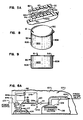
- FIG. 6 A block diagram of the circuit and fluid flow paths for the dispenser apparatus as connected within a hydraulic, manually controlled gravity feed system is illustrated in Fig. 6.
- dispenser housing 20 is illustrated as mounted to a side wall 100 of a washing machine 105.
- Washing machine 105 has a wash tank 106 for storing a supply of detergent solution for use within the machine.
- Conduit 29 extends from outlet port 27 of housing 20 and is connected to a hose clamp extension 107 extending through side wall 100 of washing machine 105 and terminating at a position directly overlying wash tank 106.
- Washing machine 105 also has a fresh water supply line 42a connected to a pressurized source of water (not illustrated). Water line 42a directly provides clean rinse water to the.
- a rinse valve 109 is connected to water supply line 42a at a position upstream from the rinse head 110 and upstream from the input to water supply line 42 for controlling the flow of water to rinse head 110 and water supply line 42.
- a flow control valve III is connected in water supply line 42 leading to spray-forming nozzle 38 to regulate the rate of flow of water to spray-forming nozzle 38.
- a safety control valve 120 is connected in the water supply line 42.
- the safety control valve 120 is, in the preferred embodiment, a solenoid actuated valve having an input control terminal 120a and a common terminal generally designated at 120b.
- the common terminal 120b is directly connected to a reference potential generally designated at 200.
- the first conductor 54a leading from the safety switch 50 is directly connected to an appropriate power source 201.
- the second conductor 54b leading from the safety switch 50 is directly connected to the control input terminal 120a of the solenoid actuated safety control valve 120.
- Control of the dispensing of the chemical block 80 from dispenser 20 is done by controlling the flow of water to spray nozzle 38. This may be done in a number of ways including mechanical means such as hydraulic timer valves and electrical means such as electrical switching within the washing machine control system (not illustrated), conductivity sensing means in wash tank 106, and electrical timers.
- the power source 201 is connected via conductor 64a to the input terminal 61a of float switch 60.
- Conductor 64b then connects float switch 60 with the input terminal 51a of safety switch 50 and conductor 54b connects the output terminal 51b of the safety switch 50 with the input terminal 120a of the safety control valve 120.
- the safety control valve 120 is normally closed to water flow therethrough. The power to open safety control valve 120 and allow the flow of water to spray nozzle 38 reaches valve 120 only if the float switch 60 is in its electronically closed state (level of chemical solution below the minimum level) and safety switch 50 is in its electronically closed state (door 34 closed).
- housing 20 is illustrated as mounted to side wall 100 of a washing machine 105 at a position above wash tank 106 of washing machine 105 such that conduit 29 and associated hose connecting extension 107 dispense the contents of collector portion 25 of housing 20 directly into reservoir 106.
- Water supply line 42 is directly connected to a source of pressurized water (not illustrated).
- Solenoid safety control valve 120 is connected in water supply line 42 between spray-forming nozzle 38 and the water supply source.
- Solenoid valve 120 has an input control terminal 120a and a common terminal 120b which is directly connected to a ground potential 200.
- First conductor 54a leading from safety switch 50 is directly connected to a power source 201.
- Second conductor 54b leading from safety switch 50 is connected to a positive power supply input terminal 150a of an electronic control module 150.
- Electronic control module 150 further has a reference supply input terminal 150b which is directly connected to common potential 200, a first signal input terminal 150c, a second signal input terminal 150d, and a signal output terminal 150e.
- Signal output terminal 150e of electronic control module 150 is directly connected to control input terminal 120a of solenoid valve 120.
- First and second signal input terminals 150c and 150d of electronic control module 150 are directly connected by means of a pair of signal flow paths 151 and 152 respectively to terminals of a conductivity cell 125.
- Conductivity cell 125 is mounted within reservoir 106 of washing machine 105 for sensing the electrical conductivity of the solution contained therein.
- an electronic control module 150 which may be utilized in the present invention is disclosed in U.S. Pat. No. 3,680,070, issued to Markus I. Nystuen.
- the electronic control module 150 is normally operable to provide a de-energizing signal output at its output terminal 150e when conductivity cell 125 indicates the conductivity (i.e. the chemical concentration level) of the wash tank solu- .tion within wash tank 106 is at or above a predetermined level and is operable to provide an energizing output signal at its signal output terminal 150e whenever conductivity cell 125 indicates that the conductivity (concentration level) of the solution within reservoir 106 has dropped below a predetermined minimum level.
- the signal output appearing at output terminal 150e of electronic control module 150 is used to energize input control terminal 120a of solenoid valve 120.
- the circuits within electronic control module 150 are energized from power source 201 by means of the serially connected safety switch 50. Therefore, whenever the safety switch 50 is operative in a non-conducting (open) mode, electronic control module circuits will be disabled, preventing passage of an energizing signal to solenoid valve 120, regardless of the conductivity indication status of conductivity cell 125.
- Conductivity cell 125 may be of any type of such cell well known in the art, which provides an electrical output signal that varies in response to the electrical conductivity of the solution in which it is immersed.
- the solid block of chemical used in cleaning processes is packaged in an open faced, sturdy container 500 having a cross-sectional area such that the container may easily pass into torroidal cavity 44 as the chemical 80 contained therein is used.
- the open face is covered with a sturdy thermoplastic threaded cap 510.
- the crosssectional area of container 500 must be slightly greater than the cross-sectional area of the horizontal portion 45 of support screen 40. This is necessary to allow the container 500 to pass easily around support screen 40 and into torroidal cavity 44.
- the container 500 may be made of any sturdy material capable of preventing the passage of the chemical into the surrounding atmosphere. Examples of such materials include stainless steel, glass, and thermoplastics such as polyethylene and polypropylene.
- the cap 510 is removed, the container 500 inverted over the access port 24 of the dispenser 20 and the container 500 and chemical block 80 contained therein is placed with surface 81 of chemical block 80 contacting. the horizontal portion 45 of the support screen 40. Door 34 is then placed in a closed position over the access port 24.
- a container 500 containing a block of solid chemical 80 is loaded into upper storage portion 21 of housing 20 through access port 24 by removing cap 50, inverting container 500, open face 501 down, directly over access port 24 and placing container 500 and chemical 80 onto the horizontal portion 45 of support screen 40.
- the container walls 506 will extend around support screen 40 such that only the block of chemical 80 contained within the container 500 will contact the support screen 40.
- the container 500 will envelop the support screen 40 by passing into torroidal cavity 44. This maintains a constant distance between nozzle 38 and the exposed, dissolving surface 81 of the solid block of chemical 80, thereby maintaining a substantially constant rate of dispensing.
- Solenoid valve 120 is connected so as to be open to fluid flow while in receipt of an energizing signal from the safety switch 50. However, when signal flow to solenoid valve 120 is blocked by means of open safety switch 50, solenoid valve 120 will close, blocking further fluid flow to spray-forming nozzle 38. Under normal operation, a fluid flow path is established from the water source through water supply line 42 to spray-forming nozzle 38 whenever rinse valve 109 is opened, either electronically or manually.
- spray-forming nozzle 38 When provided with fluid flow therethrough, spray-forming nozzle 38 will direct a spray pattern at the bottom surface of support screen 40, wetting that chemical 80 carried immediately thereabove 81, which dissolves and passes in solution through support screen 40 to collector portion 25 of housing 20.
- concentrated chemical solution is produced in this arrangement of the apparatus, whenever rinse valve 109 is opened and door member 34 is closed so as to enable safety switch 50.
- the concentrated detergent solution passes through outlet port 27 of housing member 20 and is directed by conduit 29 to its utilization point.
- the sodium hydroxide bead was added to the sodium hydroxide 50% solution, heated to 1750 F. and mixed.
- the sodium tripolyphosphate was then added and mixed until uniform, about 10 to 20 minutes. This mixture was poured into a container and cooled rapidly to solidify the product.
- the polyethylene glycol was melted at a temperature of about 160° F.
- the sodium xylene sulfonate granules or flakes were added and mixed into the polyethylene glycol melt.
- Pluronic L62 and F87 were then added and mixed until the melt was uniform, about 10 to 20 minutes.
- the mixture was then poured into a container and allowed to cool and solidify.
- the nonyl phenol ethoxylate 15 moles of ethylene oxide and polyethylene oxide were mixed together and melted at a temperature of about 160 to 1800 F.
- the product was then poured into a container and cooled below its melting point of about 1500 F.
- the polyethylene oxide and the dimethyl distearyl ammonium chloride were mixed together and melted at a temperature of about 160 to 180° F.
- the remaining items were then added to the hot melt and mixed until a uniform product was obtained, about 10 to 20 minutes.
- the mixed product thusly obtained was then poured into a container and cooled below its melting point of about 140° F.
- One thousand, three hundred grams of sodium hydroxide was placed in a 4 liter glass beaker and heated under agitation to about 190-200° F. Eight hundred, fifty grams of Dequest 2000 and 325 grams of 50% solution polyacrylic acid, molecular weight 5,000 were slowly added to the 50% sodium hydroxide solution contained in the glass beaker. Six hundred, ninety grams of nonylphenol ethoxylate, 9.5 mole ratio, 4 grams of Tinopal CBS, and 1,831 grams of sodium hydroxide were added together and heated to about 180-1900 F. The two melts were then combined in the beaker and agitated for about 30 minutes. The solution was slowly cooled under constant agitation to about 160° F. The product was then poured into a plastic package and sealed.
- compositions described in Examples I and II are most favorably dispensed in the dispenser of this invention because contact with these highly alkaline products can be harmful.
- Two identical cylindrical containers having a diameter of about 15 cm and a height of about 17.5 cm were filled with about 5,000 grams of Tri-Star detergent as described in Example I.
- the containers were allowed to cool to room temperature before dispensing.
- One of the containers was placed in the dispenser of this invention which maintained a constant distance of about 8 cm between the spray nozzle and the exposed erosion surface of the detergent as the detergent was consumed.
- the other container was placed in a dispenser similar to the dispenser of this invention except that the support screen was a flat horizontal screen which did not allow the container to descend as the detergent was consumed. Therefore, the distance between the spray nozzle and the exposed erosion surface of the detergent increased from about 8 cm to about 25 cm as the detergent was consumed.
- a dispensing cycle was then established for both dispensers whereby water maintained at a temperature of about 128-131 0 F. was sprayed at a pressure of about 20 psi onto the exposed erosion surface of the detergent for a period of 35 seconds every 20 minutes. At random points in the dispensing cycle the amount of detergent dispensed during a 35 second spray was measured by weighing the container immediately before and after the spray.
- Example VII was repeated using the Solid Sour Soft of Example VI in place of the High Alkaline Institutional laundry detergent.
- the results of the experiment are tabulated in Table 2 and graphically depicted in Figure II.
- the concentration of the sour/soft solution dispensed from the increasing distance dispenser substantially decreases as the sour/soft is consumed, with about a 10:1 change in the number of grams of softener dispensed in a second spray during consumption of the sour/soft.
- the concentration of the sour/soft solution dispensed from the constant distance dispenser remains relatively constant during the entire consumption of the sour/soft.
Landscapes
- Chemical & Material Sciences (AREA)
- Chemical Kinetics & Catalysis (AREA)
- Life Sciences & Earth Sciences (AREA)
- Engineering & Computer Science (AREA)
- Oil, Petroleum & Natural Gas (AREA)
- Wood Science & Technology (AREA)
- Organic Chemistry (AREA)
- Feeding, Discharge, Calcimining, Fusing, And Gas-Generation Devices (AREA)
- Cleaning By Liquid Or Steam (AREA)
- Automatic Analysis And Handling Materials Therefor (AREA)
- Investigating Or Analysing Biological Materials (AREA)
- Earth Drilling (AREA)
- Detail Structures Of Washing Machines And Dryers (AREA)
- Beans For Foods Or Fodder (AREA)
- Sampling And Sample Adjustment (AREA)
- Bidet-Like Cleaning Device And Other Flush Toilet Accessories (AREA)
- Silver Salt Photography Or Processing Solution Therefor (AREA)
- Road Signs Or Road Markings (AREA)
- Non-Flushing Toilets (AREA)
- Sanitary Device For Flush Toilet (AREA)
- Cleaning In General (AREA)
- Electrical Discharge Machining, Electrochemical Machining, And Combined Machining (AREA)
Abstract
Description
- The invention relates broadly to the dispensing of solid, water soluble compositions used in cleaning processes. More particularly, the invention relates to the dispensing of cast chemical compositions used in cleaning processes. Such chemicals include detergents, rinse aids, and the like. Typically, the cast chemical composition is dispensed by contacting the chemical with an aqueous liquid to create a concentrated working solution.
- Automated institutional and industrial ware washing machines are generally configured with one wash tank for maintaining a readily available supply of a cleaning solution for use in the machine. During normal usage at least a portion of the cleaning solution is discarded in order to keep the remaining cleaning solution as clean as possible. Fresh water or other clean recycled water is then added to the wash tank to maintain an appropriate liquid level, thereby diluting the concentration of detergent in the cleaning solution. To maintain the cleaning solution at the most efficient cleaning concentration, a measured amount of a concentrated aqueous detergent solution is periodically added to the wash tank by an auxiliary detergent dispenser to form a cleaning solution of the desired strength.
- Automated institutional and industrial ware washing machines may also be constructed to add a rinse aid to the rinse water from an auxiliary dispenser to promote sheeting and reduce water spotting on the washed ware.
- Automated institutional and industrial fabric washing machines typically create a new cleaning solution for each cleaning cycle to which is added detergent, bleach, fabric softener and other optional additives. Typically, these fabric washing additives are added to the wash water by auxiliary dispensers.
- Chemical dispensers used in the processes described above typically have been designed for automatic or semi-automatic operation. Automatic dispensers eliminate the need for constant operator attention to the cleanliness of the wash water and concentration of chemical in the wash tank. Further, automated dispensers minimize operator error due to operator misjudgment in timing or in the amount of chemical to be added, and provides greater accuracy in maintaining the optimum concentration level of chemical in the system.
- A number of different techniques have been developed and used for converting solid chemicals used in cleaning processes into a concentrated solution. The majority of such devices have been designed to convert solid powdered detergent. See for example Daley et al, U.S. Pat. No. 3,595,438, issued July 27, 1971; Moffet et al, U.S. Pat. No. 4,020,865, issued May 3, 1977; and Larson et al, U.S. Pat. No. 4,063,663, issued Dec. 20, 1977. For this reason the background of chemical dispensers will be further discussed with respect to the dispensing of a detergent.
- One common detergent dispenser technique for converting powdered detergent, is the so-called "water-in-reservoir" type. In the water-in-reservoir type dispenser, the powdered detergent is completely submerged in an aqueous solution. A stand-pipe, usually located near the center of the dispenser tank, maintains a constant level of concentrated solution within the dispenser tank. As water is added to the dispenser tank, a concentrated, often saturated detergent solution or slurry is formed by the swirling action and agitation of the powdered detergent. The added water also causes a portion of the solution or slurry in the reservoir to flow into the stand-pipe, which directs the concentrated detergent solution to the wash tank of the washing apparatus. Such a dispensing technique is generally not practical for dispensing powdered detergents containing incompatible components (such as an active chlorine source in combination with a defoamer) as the incompatible components tend to react upon contact when in solution. Further, there are possible safety hazards involved with the use of such dispensers. Charging or recharging of water-in-reservoir type dispensers requires an operator to place detergent directly into standing water. Since water-in-reservoir type dispensers are typically mounted at about eye level or higher with respect to the operator, any splashing or splattering caused by adding the detergent directly into the concentrated solution poses the danger of spilling concentrated detergent solution onto the eyes, face and skin of the operator. This is particularly hazardous when adding highly alkaline or other such hazardous chemicals.
- Another technique for converting a powdered detergent into a concentrated detergent solution involves pouring the powdered detergent onto one side of a conical or hemispherical screen having a mesh size smaller than the powdered detergent particles supported thereby. The powdered detergent which directly overlies the support screen is dissolved as needed by a fine mist or spray of water from a nozzle disposed below and on the other side of the screen. The concentrated detergent solution formed by the action of the water falls by gravity into an underlying reservoir, or is directed by a conduit to the wash tank of a washing apparatus. (See, for example, U.S. Pat. Nos. 3,595,438 issued to Daley et al; 4,020,865 issued to Moffat et al; 4,063,663 issued to Larson et al.; and 2,371,720 issued to Stine.) This technique solves many of the problems associated with the water-in-reservoir type of dispenser as (i) the entire charge of powdered detergent is not wetted, and (ii) an operator loading detergent into the dispenser is not placing detergent directly into standing water and therefore is not subjected to possible boil-over or splattering of the detergent solution.
- While the powdered detergent dispensers such as described by the Daley, Moffat and Larson patents have represented significant contributions to the art of detergent dispensing, the use of powdered solid detergent in general has a number of drawbacks in commercial applications. Due to increased sanitary standards and demands for shorter wash times, recently developed detergents have relatively more complex compositions that are more hazardous to the user, less stable, and more difficult to dissolve in a satisfactorily uniform manner. Powdered detergents generally dissolve readily because of their high specific surface areas. However, when such powdered detergents include a mixture of a number of components having relatively different dissolving rates, the detergent is susceptible to differential solubility problems in automatic detergent dispensers; the extent of the solubility problem depending upon the rate of dispensing and the residence (dwell) time of contact between the detergent powder and the dissolving liquid. Those particles having a greater rate of solubility and/or a greater specific surface tend to dissolve first, whereas those having a lower solubility rate and/or a lower specific surface tend to dissolve last.
- Another problem associated with powdered detergents is the incompatibility and/or instability of particular detergent components required for good cleaning action, when these components are combined in a powdered detergent composition.
- Still another problem inherent in powdered detergent is segregation of different sized and/or weighted particles during manufacturing, shipping and handling. Even when uniform distribution can be achieved during manufacture, subsequent shipping and handling may cause segregation, leading to non-uniformity in the composition of the detergent when it is withdrawn from the container.
- A further disadvantage of powdered detergents is that they are quite susceptible to spillage.
- Another form of solid detergent is the detergent briquette which comprises pre-shaped briquettes of solid detergent. Dispensing systems for dissolving detergent briquettes are known in the art. See, for example, U.S. Pat. Nos. 2,382,163, 2,382,164 and 2,382,165 all issued Aug. 14, 1945 to MacMahon, and U.S. Pat. No. 2,412,819, issued Dec. 17, 1946 to MacMahon. In the MacMahon systems, the detergent briquettes are dispensed from a modified water-in-reservoir type dispenser wherein a number of the briquettes are held in a mesh basket forming a slot across the diameter of a reservoir. A stream of water directed against the lowermost briquette, in combination with the swirling action of the water engaging the submerged portion of the lower-most briquette, provides the dissolving action. The primary advantage of using detergent briquettes in such dispensers is that the user can visually determine when the detergent dispenser reservoir requires additional detergent. As with the water-in-reservoir dispensers, however, water is left standing in the reservoir, and a portion of the briquettes are submerged within that water. Accordingly, where there are incompatible components within the detergent briquettes, there can be undesirable interaction therebetween. Further, if the detergent contains a defoamer, that defoamer tends to float to the top of the reservoir during periods of inactivity, forming a slag at the water surface. For these and other reasons, the briquette detergent approach has not attained that degree of commercial success in the conventional institutional and industrial washing machine art as has the powdered detergent dispensing approach.
- Still another, more recent, form of solid detergent is the "cast" or block form, comprising detergent cast within a mold or container. Dispensing systems for these solids are known in the art. See, for example, WO- 8 001 160, U.S. Pat. No. 4 426 362 issued to Copeland et al and commonly owned copending U.S. patent applications Serial Nos. 234 940 and 509 916. The cast detergent is dispensed by spraying a solvent onto the detergent block within the container, thereby dissolving the exposed surface of the detergent to form a concentrated working solution. The concentrated working solution falls into a reservoir or is directed by a conduit to the wash tank of a washing apparatus. When the chemical compound within the container is completely utilized, the exhausted container is simply discarded and a fully charged container placed in the dispenser.
- The use of solid cast detergents has presented great innovations to the dispensing of chemicals used in the cleaning process but additional features have been sought by users of solid block dispensers including (i) the ability to provide a relatively constant chemical dispensing rate, and (ii) a reduced unit cost of the chemical.
- Containers utilized for storing and dispensing of solid chemicals used in cleaning processes depend upon the form of the solid detergent. Flaked or granular chemicals are typically packaged in sturdy paper board containers treated to prevent the passage of moisture into the package. Typically, the granular chemical is dispensed from the box by either (i) ripping a hole in the box or (ii) opening a reclosable spout provided on a side panel of the box. This type of container is unsuitable for nonflowing, solid block wash chemicals.
- Containers for solid tablet or briquette chemicals used in cleaning processes typically take the form of paper or plastic wrappers which completely surround the tablet or briquette. The chemical is dispensed by removing the wrapper entirely and placing the tablet or briquette into the dispenser. The drawbacks associated with this type of container are: (i) they require physical contact of the skin with the chemical which should be avoided, and with some cleaning compositions such as highly alkaline compounds, can cause severe "burns", and (ii) the chemical must be formed in one step and packaged in a second step, requiring additional time and expense for packaging.
- Solid, cast chemicals used in cleaning processes are preferably cast in a sturdy solid plastic container which can act as a mold, a shipping and storage container, and a dispenser housing. The cast chemical may be dispensed by inverting the container over a spray nozzle and impinging solvent directly into the container and onto the exposed surface or surfaces of the chemical contained therein.
- Hazardous chemicals used in cleaning processes such as highly alkaline detergents are preferably packaged such that they can be dispensed without coming into physical contact with the human body. The paper and/or plastic wrappers typically utilized with tablet and briquette solid detergents are not adequate for this purpose as they require a large amount of handling to remove the wrapper and place the tablet or briquette into the dispenser after the wrapper has been removed.
- Accordingly, a need exists for a dispensing apparatus which can simply, safely, efficiently and inexpensively dispense a homogeneous, uniform, concentrated chemical solution from a solid block of wash chemical at relatively constant concentrations and in certain applications, a need exists for an inexpensive solid block chemical container which minimizes the possibility of skin contact with the wash chemical; allows the solid wash chemical to be formed and packaged in a single step; and provides for a substantially constant rate of chemical dispensing.
- In US-A 2 371 720, referred to above, there is disclosed a dispenser having a spray means for directing a spray onto a chemical held above a screen to produce an aqueous chemical of substantially constant concentration that is dispensed by the dispenser, the chemical being a mass of caked or powdered chemical such as soap.
- According to the present invention, there is provided a dispenser having a spray means for directing a spray onto a chemical held above a screen to produce an aqueous chemical solution of substantially constant concentration that is dispensed by the dispenser, characterised in that the dispenser is a dispenser for dispensing an aqueous chemical solution from a solid block of chemical retained within a container such that the chemical and container move as a single unit during dispensing, the dispenser comprising:
- (a) a container surrounding a solid block of chemical, the solid block of chemical having at least one exposed surface to be sprayed;
- (b) a screen having a horizontal top portion, a vertical circumferential wall creating a central cavity, and a lower support in contact with a housing. for maintaining a constant distance between the spray means and the exposed surface of the solid block of chemical to be sprayed in order to maintain a substantially constant chemical solution concentration during the dispensing from the solid block of chemical; and
- (c) a spray means for directing a uniform spray such that the spray impinges on at least one exposed surface of the solid block of chemical, said spray means being positioned within the central cavity created by said vertical circumferential wall of said screen.
- Thus, the present invention provides a chemical dispenser for dispensing a concentrated chemical solution from a solid block of chemical for use in cleaning processes. The dispenser is configured in such a manner so as to maintain a relatively constant rate of dispensing by maintaining a constant distance between the dissolving spray nozzle and the exposed and erodable surface of the solid block of chemical. The following explanations concern useful details of the invention. The dispenser includes (i) a container surrounding the solid block of chemical, the solid block of chemical having at least one exposed surface; (ii) a spray means for directing a uniform spray such that the spray impinges at least one exposed surface of the solid block of chemical; and (iii) a screen for maintaining a constant distance between the spray means and the exposed surface of the solid block of chemical to be sprayed in order to maintain a substantially constant chemical solution concentration during the entire lifetime of the solid block of chemical.
- In more detail, the dispenser includes a housing suitable for fixed mounting to a solid mounting surface. The dispenser can be mounted vertically or horizontally, directly to a washing apparatus to which the concentrated chemical solution is to be supplied, adjacent to such washing apparatus, or at a position remote from such washing apparatus.
- The housing can include (i) an upper storage portion for retainably holding a mass of solid block chemical; the storage portion having an upwardly disposed access port through which a solid block chemical is loaded into the housing; the access port normally covered by a door mounted onto the housing; and (ii) a lower collector portion configured in a funnel shape that downwardly converges to an outlet port. The housing is designed for mounting so that the vertical height of the outlet port from the collector portion of the housing can be higher than the utilization point. A conduit can then be connected to the outlet port of the housing for directing the chemical solution formed in the dispenser, by means of gravity feed, from the collector portion of the dispenser to its utilization point. Alternatively, the chemical solution may be pumped from the collector portion of the dispenser to its utilization point.
- A three-dimensional, cylindrical support screen is retainably mounted within the housing, coupled to the housing at the points therein defining the intersection of the upper storage portion and the lower collector portion of the housing. The support screen extends upward into the storage portion of the dispenser and defines an annular cavity between the walls of the upper storage portion of the housing and the support screen such that a chemical container may envelop the support screen as the chemical held therein is utilized by dropping into the annular cavity. This maintains a vertically constant distance between the spray nozzle and the chemical which aids in maintaining a relatively constant rate of dispensing in this dispenser. The support screen supports the solid block of chemical only (not the chemical container) without significantly impeding access of a water spray onto the lower exposed surface of the chemical (e.g. screen size about 2.5 cm).
- Spray forming means are axially mounted in the housing below the support screen. The spray forming nozzle is connected to a pressurized source of water by means of a water supply line. A spray control means comprising a valve in the water supply line controls the flow of water to the spray-forming nozzle. In operation, the valve normally blocks water flow to the nozzle and is operative to its open position only upon receipt of an external control signal. Upon receipt of such a control signal, the valve opens and water flow is allowed to flow through the supply line, and is dispersed by the spray forming means into engagement with substantially the entire lower surface of the chemical block supported immediately above the support screen. Spray from the nozzle is of relatively low pressure (typically 10 to 25 p.s.i.) and wets only that portion of the solid block chemical carried immediately above the support screen. The dissolved chemical passes in solution through the support screen, is directed by the underlying collector portion of the housing to the outlet port thereof and passes through a chemical solution conduit to its utilization point.
- In an alternative embodiment a chemical solution pump in the chemical solution conduit is used to pump the chemical solution to its utilization point. The chemical solution pump is operative in response to a control signal to begin dispensing. A level indicator is positioned within the collector portion of the housing and operatively connected to the spray control means for controlling the flow of water to the nozzle. When the level of chemical solution in the collector portion of the housing decreases below a minimum level due to operation of the chemical solution pump, the level indicator is electronically closed and a control signal is sent to the spray control valve. Upon receipt of such a control signal the spray control valve opens to the flow of water therethrough and additional chemical solution is formed until the level indicator indicates that the minimum level has been achieved. The rate of creation of chemical solution should be greater than the rate at which chemical solution is pumped out of the collector portion of the housing to prevent the entrainment of air. Also, the minimum level of chemical solution should be set below the nozzle to prevent any interference with the spray of water. This type of dispenser is particularly useful when introducing the chemical solution into a pressurized line or tank or into a remote utilization point and prevents the entrainment of air into the pump and early pump failure.
- Optionally, a 1/4 to 1/20 inch (0.64 to 0.13 cm) lower screen can be placed in the collector portion of the housing between the spray nozzle and the outlet port to catch any undissolved chunks of chemical which have broken away from the main block and which are small enough to pass through the support screen. This prevents small chunks of chemical from collecting in the outlet port or the conduit connected thereto and blocking the flow of concentrated chemical solution out of the dispenser.
- An electrically or mechanically actuated safety control switching circuit can be connected to sense the operative position of the door covering the access port to the housing and prevent water spray from the nozzle whenever the door is not in its closed position overlying the access port. This prevents the spray of concentrated chemical solution while an operator is loading the dispenser.
- While the present invention will be described in combination with a particular configuration of the dispenser housing, it will be understood that other configurations could be designed. Further, while the preferred embodiment of the invention will be described in combination with specific electronic control modules for providing control signals to the spray control means regulating water flow to a spray nozzle, it will be understood that other control circuits, including mechanical, hydraulic, and optical systems, could equally well be configured. Similarly, while specific switching circuits and techniques will be described with respect to the preferred embodiments of this invention, other safety control means including purely mechanical linkage systems could equally well be devised. Further, while specific configurations of the support screen and container are described, other alternative configurations may be used in accordance with this invention so long as the container is capable of passing between the walls of the housing and the support screen so as to maintain a constant distance between the chemical and the spray forming means as the chemical is utilized (e.g. an oval or square, instead of circular, container and support screen).
- The solid block of wash chemical is housed in a sturdy container having at least one exposed surface and a removable cap or lid enclosing the exposed surface(s) before use.
- The chemical may be cast or compressed directly into the container with the cap or lid attached to the container by means of a threaded fitting, a friction fitting, adhesive, etc. Preferably a sturdy, thermoplastic, threaded cap is securely attached to the container, completely enclosing the chemical contained therein from environmental effects. At the point of use, the cap or lid is removed, the container inverted over the access port of the dispenser and the chemical placed onto the support screen; the support screen contacting only the chemical within the container.
- As used herein, the term "utilization point", when used in combination with chemical solution, refers to the place where the solution is used such as a wash tank, a spray rinse nozzle, etc.
- As used herein, the term "chemical" refers to those chemical compounds or mixtures commonly added to aqueous liquids present in machine washing units to aid in the cleaning and rinsing of fabrics and wares. Such chemicals include detergents, softeners, bleaches, rinse aids, etc.
-
- FIGURE I is a front view, with portions thereof broken away, of one embodiment of the dispenser of this invention.
- FIGURE 2 is a side view of the dispenser disclosed in Fig. I without the optional chemical solution pump.
- FIGURE 3 is an enlarged front view, with portions thereof broken away, of the collector portion of the dispenser shown in Fig. 2.
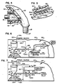
- FIGURE 4 is an enlarged fragmentary back view, with portions thereof broken away, of the lower portion of the collector portion of the dispenser shown in Fig. 2.
- FIGURE 5 is an enlarged cross-sectional view of the safety control switch mounted upon the door of the dispenser shown in Fig. 2.
- FIGURE 5a is an enlarged cross-sectional view of the level indicator switch shown in Fig. I.
- FIGURE 6 is a schematic block diagram illustrating the circulatory and basic electrical signal flow paths for one embodiment of the dispenser of this invention.
- FIGURE 6a is a schematic block diagram illustrating the circulatory and basic electrical signal flow paths for a second embodiment of the dispenser of this invention which utilizes a chemical solution pump and a level indicator switch.
- FIGURE 7 is a schematic block diagram illustrating the circulatory and basic electrical signal flow paths for a third embodiment of the dispenser of this invention which utilizes conductivity sensing means in the wash tank to regulate operation of the dispenser.
- FIGURE 8 is a perspective view of the container of this invention.
- FIGURE 9 is a front view of the container of Fig. 8.
- FIGURE 10 is a graphical comparison of the concentration of the chemical solution dispensed from a constant nozzle to chemical distance dispenser of the invention versus an increasing nozzle to chemical distance dispenser.
- FIGURE II is a graphical comparison of the concentration of the chemical solution dispensed from a constant nozzle to chemical distance dispenser of the invention versus an increasing nozzle to chemical distance dispenser.
- Referring to the Figures, there is generally disclosed at 20 a housing. The housing has a generally cylindrical
upper storage portion 21 having a cylindricalinner wall 22. Thewall 22 defines aninternal cavity 23. The upper terminous of thestorage portion 21 defines anaccess port 24 intocavity 23 ofstorage portion 21. -
Inner wall 22 ofhousing 20 converges in the downward direction, defining a lower funnel-shapedcollector portion 25 ofhousing 20.Inner wall 22 ofhousing 20 is configured to form anannular flange 26 circumferentially extending aroundinner wall 22 ofhousing 20 at the juncture ofupper storage portion 21 andlower collector portion 25. The lower terminous ofcollector portion 25 defines anoutlet port 27 frominternal cavity 23 for passage therethrough of solution collected bycollector portion 25.Outlet port 27 has ahose clamp extension 28 having a plurality of annular ribs configured for engaging the inner walls of a connecting hose orconduit 29. - The
outlet port 27 may be directly connected with a utilization point byconduit 29. The chemical solution created may be fed to the utilization point by gravity flow or by means of asolution pump 30. -
Housing 20 may be constructed of any suitable material which is capable of withstanding exposure to highly caustic solutions, and is preferably configured of stainless steel or molded plastic material. - A pair of mounting
plates 32 are connected to and extend rearwardly from the outer surface ofhousing 20 for securely mountinghousing 20 to a sturdy surface, generally designated as 100. A brace member 33 extends across the back surface ofhousing 20, connecting the pair of mountingplates 32 and adding structural support to thedispenser housing 20. - A
door 34 is sized to completely cover and sealingly engageaccess port 24. Thedoor 34 is pivotally mounted to the brace member 33 at 35 for pivotal motion between a closed position, illustrated in full line in Fig. 2, to an open position, illustrated in dashed lines in Fig. 2. - An outwardly projecting
coupling portion 36 extends from the side ofcollector portion 25. Atube fitting insert 37 is secured withincoupling projection 36 and projects throughinner wall 22 ofcollector portion 25 ofhousing 20. A spray-formingnozzle 38 is threaded into the end oftube insert 37 and is axially aligned withininner cavity 23 ofhousing 20 in a direction so as to direct an upwardly projected spray pattern therefrom.Tube fitting insert 37 is provided with an O-ring seal 39. - A three-dimensional, cylindrical, upwardly extending
support screen 40 is mounted in resting engagement uponflange 26 ofhousing 20.Support screen 40 preferably has about 0.3 to 7.5 cm, most preferably about 2.5 cm square openings in order to support acontainer 500 ofchemical 80 without significantly interfering with the impingement of water sprayed fromnozzle 38 onto the exposedsurface 81 of thechemical block 80 which contacts supportscreen 40. Thesupport screen 40 extends inwardly with support andextension portion 47 and then upwardly fromflange 26 intostorage portion 21 ofhousing 20 with awall 45 thereby defining an annular generally elongatedtorroidal cavity 44 between theinner wall 22 ofhousing 20 and thevertical wall 45 ofsupport screen 40.Cavity 44 has sufficient size to allow passage of thecontainer walls 506 betweeninner wall 22 ofhousing 20 andvertical wall 45 ofsupport screen 40 as the block ofchemical 80 is used. The height ofsupport screen 40 is determined by the depth ofcontainer 500 to be utilized in the dispenser. Preferably thesupport screen 40 extends about 15 to 30 cm intostorage portion 21 and defines a 0.6 to 2.5 cm widetorroidal cavity 44 in conjunction withinner wall 22 ofhousing 20. Thesupport screen 40 terminates in a substantially flat horizontal screen 46 whereupon the solid block of chemical 80 (but not container 500) is directly supported.Support screen 40 maintainssurface 81 of the chemical 80 at a constant vertical or distance fromspray nozzle 38 during use of theentire chemical block 80.Container 500 passes into the generally elongatedtorroidal cavity 44 as thechemical block 80 is used. By maintaining thechemical block 80 at a constant vertical height the distance between the dissolvingspray nozzle 38 and the exposed anderodable surface 81 of thechemical block 80 remains constant which, as I have discovered, aids significantly in maintaining a constant rate of dispensing. - A
lower screen 41 having about 0.63 to 0.13 cm openings may be placed incollector portion 25 ofhousing 20 betweenspray nozzle 38 andoutlet port 27 to catch any undissolved chunks ofchemical 80 which break away from thechemical block 80 and which are small enough to pass throughsupport screen 40. This prevents small chunks ofchemical 80 collecting inoutlet port 27 orconduit 29 and blocking the flow of concentrated chemical solution out ofdispenser 20. - A water
supply inlet pipe 42 is connected totube insert 37 and is in communication therewith for providing a source of water flow to spray-formingnozzle 38.Water supply line 42 may be configured to pass through one of the mountingplate members 32, as illustrated in Figs. I and 2, to receive structural support therefrom. A siphonbreaker 43 interruptswater supply line 42 for controlling the flow of water tonozzle 38. - In the embodiment utilizing the
chemical solution pump 30, thepump 30 is operative in response to a control signal. A float 31 is positioned withincollector portion 25 ofhousing 20 and is operatively connected byfloat extension bar 61 tolevel indicator switch 60. When the level of chemical solution incollector portion 25 ofhousing 20 falls below a minimum level due to operation ofchemical pump 30,level indicator switch 60 is electrically closed by the downward motion of float 31 and proportional change in the slope offloat extension bar 61. An electrical signal is then allowed to pass throughlevel indicator switch 60 onto spray control means 43 and spray control means 43 is opened to the flow of water therethrough. Chemical solution is then formed until float 31 rises to or above the minimum level whereinlevel indicator switch 60 is electrically opened.Level indicator switch 60 is in communication withfloat extension bar 61 for sensing the operative angle offloat extension bar 61; the angle offloat extension bar 61 changing in proportion with the change in height of float 31. In the preferred embodiment,level indicator switch 60 comprises a mercury actuated switch, diagramatically illustrated in Fig. 5a. Referring thereto,level indicator switch 60 generally has a pair of contacts 61a and 61b projecting within an insulatingbulb 62 which entraps a fluid conductive medium 63 such as mercury.Level indicator switch 60 is mounted uponfloat extension bar 61 such that whenfloat extension bar 61 is operatively positioned so as to indicate the level of chemical solution incollector portion 25 is at or above the minimum level, mercury 63 does not provide an electrical shorting path between first and second terminals 61a and 61b ofswitch 60 and thefloat switch 60 is electrically open. When float 31 is lowered due to a decrease in the amount of chemical solution incollector portion 25, the angle offloat extension bar 61 is pivotally altered and the mercury 63 flows withinbulb 62 to engage both the first and second terminals 61a and 61b so as to provide an electrical circuit path between the first and second terminals 61a and 61b, thus electrically closingfloat switch 60. Conduction paths are provided from first and second terminals 61a and 61b by means of a pair ofconductor members 64a and 64b respectively, conduction member 64a coupled to apower source 201 andconduction member 64b coupled to first terminal 51a ofsafety switch 50 whensafety switch 50 is used; and to spray control means 43 whensafety switch 50 is not used. - This type of dispenser is particularly useful when introducing the chemical solution into a pressurized line or tank or to a remote utilization point. It prevents the entrainment of air into
wash chemical pump 30 and early failure of thepump 30. - A
safety switch 50 is mounted to door 34 for movement therewith and senses the operative position ofdoor 34 relative to accessport 24 ofhousing 20. In the preferred embodiment,safety switch 50 comprises a mercury actuated switch, diagrammatically illustrated in Fig. 5. Referring thereto,safety switch 50 generally has a pair of contacts 51a and 51b projecting within an insulatingbulb 52 which entraps a fluid conductive medium 53 such as mercury.Switch 50 is mounted upondoor 34 such that whendoor 34 is operatively positioned so as to close external access to theinternal cavity 23 ofhousing 20, themercury 53 provides an electrical shorting path between first and second terminals 51a and 51b ofswitch 50. Whendoor 34 is pivotally open so as to enable access tointernal cavity 23 ofhousing 20, themercury 53 flows withinbulb 52 away from engagement with the first terminal 51a so as to break the electrical circuit path between first and second terminals 51a and 51b, thus electrically openingsafety switch 50. Conduction paths are provided from first and second terminals 51a and 51b by means of a pair ofconductor members conduction member 54a coupled to second terminal 61b offloat switch 60 when solution pump 30 is used and to a power sourced 201 when solution pump 30 is not used; andconduction member 54b coupled to spray control means 43. - A block diagram of the circuit and fluid flow paths for the dispenser apparatus as connected within a hydraulic, manually controlled gravity feed system is illustrated in Fig. 6. Referring thereto,
dispenser housing 20 is illustrated as mounted to aside wall 100 of awashing machine 105.Washing machine 105 has awash tank 106 for storing a supply of detergent solution for use within the machine.Conduit 29 extends fromoutlet port 27 ofhousing 20 and is connected to ahose clamp extension 107 extending throughside wall 100 ofwashing machine 105 and terminating at a position directly overlyingwash tank 106.Washing machine 105 also has a fresh water supply line 42a connected to a pressurized source of water (not illustrated). Water line 42a directly provides clean rinse water to the. rinsesection 108 ofwash machine 105 and branches out towater supply line 42 for providing fresh water to spray-formingnozzle 38 as well. A rinsevalve 109, either manually or electronically controlled, is connected to water supply line 42a at a position upstream from the rinsehead 110 and upstream from the input towater supply line 42 for controlling the flow of water to rinsehead 110 andwater supply line 42. A flow control valve III is connected inwater supply line 42 leading to spray-formingnozzle 38 to regulate the rate of flow of water to spray-formingnozzle 38. Asafety control valve 120 is connected in thewater supply line 42. Thesafety control valve 120 is, in the preferred embodiment, a solenoid actuated valve having aninput control terminal 120a and a common terminal generally designated at 120b. Thecommon terminal 120b is directly connected to a reference potential generally designated at 200. - The
first conductor 54a leading from thesafety switch 50 is directly connected to anappropriate power source 201. Thesecond conductor 54b leading from thesafety switch 50 is directly connected to thecontrol input terminal 120a of the solenoid actuatedsafety control valve 120. - Control of the dispensing of the
chemical block 80 fromdispenser 20 is done by controlling the flow of water to spraynozzle 38. This may be done in a number of ways including mechanical means such as hydraulic timer valves and electrical means such as electrical switching within the washing machine control system (not illustrated), conductivity sensing means inwash tank 106, and electrical timers. - As shown in Fig. 6a, when the alternative embodiment of
dispenser 20 utilizing thechemical solution pump 30 is used, thepower source 201 is connected via conductor 64a to the input terminal 61a offloat switch 60.Conductor 64b then connectsfloat switch 60 with the input terminal 51a ofsafety switch 50 andconductor 54b connects the output terminal 51b of thesafety switch 50 with theinput terminal 120a of thesafety control valve 120. In use thesafety control valve 120 is normally closed to water flow therethrough. The power to opensafety control valve 120 and allow the flow of water to spraynozzle 38 reachesvalve 120 only if thefloat switch 60 is in its electronically closed state (level of chemical solution below the minimum level) andsafety switch 50 is in its electronically closed state (door 34 closed). - For purposes of illustration, a dispenser system utilizing a conductivity sensing means to control the flow of water to spray
nozzle 38 will be described. - Referring to Fig. 7,
housing 20 is illustrated as mounted toside wall 100 of awashing machine 105 at a position abovewash tank 106 ofwashing machine 105 such thatconduit 29 and associatedhose connecting extension 107 dispense the contents ofcollector portion 25 ofhousing 20 directly intoreservoir 106.Water supply line 42 is directly connected to a source of pressurized water (not illustrated). Solenoidsafety control valve 120 is connected inwater supply line 42 between spray-formingnozzle 38 and the water supply source.Solenoid valve 120 has aninput control terminal 120a and acommon terminal 120b which is directly connected to aground potential 200. -
First conductor 54a leading fromsafety switch 50 is directly connected to apower source 201.Second conductor 54b leading fromsafety switch 50 is connected to a positive power supply input terminal 150a of anelectronic control module 150.Electronic control module 150 further has a reference supply input terminal 150b which is directly connected tocommon potential 200, a first signal input terminal 150c, a second signal input terminal 150d, and a signal output terminal 150e. Signal output terminal 150e ofelectronic control module 150 is directly connected to controlinput terminal 120a ofsolenoid valve 120. First and second signal input terminals 150c and 150d ofelectronic control module 150 are directly connected by means of a pair ofsignal flow paths conductivity cell 125.Conductivity cell 125 is mounted withinreservoir 106 ofwashing machine 105 for sensing the electrical conductivity of the solution contained therein. - An example of an
electronic control module 150 which may be utilized in the present invention is disclosed in U.S. Pat. No. 3,680,070, issued to Markus I. Nystuen. In general, theelectronic control module 150 is normally operable to provide a de-energizing signal output at its output terminal 150e whenconductivity cell 125 indicates the conductivity (i.e. the chemical concentration level) of the wash tank solu- .tion withinwash tank 106 is at or above a predetermined level and is operable to provide an energizing output signal at its signal output terminal 150e wheneverconductivity cell 125 indicates that the conductivity (concentration level) of the solution withinreservoir 106 has dropped below a predetermined minimum level. The signal output appearing at output terminal 150e ofelectronic control module 150 is used to energizeinput control terminal 120a ofsolenoid valve 120. The circuits withinelectronic control module 150 are energized frompower source 201 by means of the serially connectedsafety switch 50. Therefore, whenever thesafety switch 50 is operative in a non-conducting (open) mode, electronic control module circuits will be disabled, preventing passage of an energizing signal tosolenoid valve 120, regardless of the conductivity indication status ofconductivity cell 125. -
Conductivity cell 125 may be of any type of such cell well known in the art, which provides an electrical output signal that varies in response to the electrical conductivity of the solution in which it is immersed. - It will be understood that
other solenoid valve 120 activation and deactivation systems and indeed purely mechanical control systems could be used to control the flow of water to spraynozzle 38 and thereby control the dispensing of chemical, within the spirit and scope of this invention. - For use in the dispenser of this invention the solid block of chemical used in cleaning processes is packaged in an open faced,
sturdy container 500 having a cross-sectional area such that the container may easily pass intotorroidal cavity 44 as the chemical 80 contained therein is used. The open face is covered with a sturdy thermoplastic threadedcap 510. The crosssectional area ofcontainer 500 must be slightly greater than the cross-sectional area of thehorizontal portion 45 ofsupport screen 40. This is necessary to allow thecontainer 500 to pass easily aroundsupport screen 40 and intotorroidal cavity 44. - The
container 500 may be made of any sturdy material capable of preventing the passage of the chemical into the surrounding atmosphere. Examples of such materials include stainless steel, glass, and thermoplastics such as polyethylene and polypropylene. - At the point of use, the
cap 510 is removed, thecontainer 500 inverted over theaccess port 24 of thedispenser 20 and thecontainer 500 andchemical block 80 contained therein is placed withsurface 81 ofchemical block 80 contacting. thehorizontal portion 45 of thesupport screen 40.Door 34 is then placed in a closed position over theaccess port 24. - Operation of the dispensing apparatus of this invention is relatively simple and is briefly described below with reference to Fig. 6. A
container 500 containing a block ofsolid chemical 80 is loaded intoupper storage portion 21 ofhousing 20 throughaccess port 24 by removingcap 50, invertingcontainer 500, open face 501 down, directly overaccess port 24 and placingcontainer 500 andchemical 80 onto thehorizontal portion 45 ofsupport screen 40. Thecontainer walls 506 will extend aroundsupport screen 40 such that only the block ofchemical 80 contained within thecontainer 500 will contact thesupport screen 40. As thechemical 80 is used thecontainer 500 will envelop thesupport screen 40 by passing intotorroidal cavity 44. This maintains a constant distance betweennozzle 38 and the exposed, dissolvingsurface 81 of the solid block ofchemical 80, thereby maintaining a substantially constant rate of dispensing. - When
door 34 is raised out of sealing engagement overlyingaccess port 24, themercury 53 withinsafety switch 50 will be disposed within insulatingbulb 52 ofsafety switch 50 so as to electrically open the signal path between first and second terminals 51a and 51b of thesafety switch 50.Solenoid valve 120 is connected so as to be open to fluid flow while in receipt of an energizing signal from thesafety switch 50. However, when signal flow tosolenoid valve 120 is blocked by means ofopen safety switch 50,solenoid valve 120 will close, blocking further fluid flow to spray-formingnozzle 38. Under normal operation, a fluid flow path is established from the water source throughwater supply line 42 to spray-formingnozzle 38 whenever rinsevalve 109 is opened, either electronically or manually. When provided with fluid flow therethrough, spray-formingnozzle 38 will direct a spray pattern at the bottom surface ofsupport screen 40, wetting thatchemical 80 carried immediately thereabove 81, which dissolves and passes in solution throughsupport screen 40 tocollector portion 25 ofhousing 20. Thus, concentrated chemical solution is produced in this arrangement of the apparatus, whenever rinsevalve 109 is opened anddoor member 34 is closed so as to enablesafety switch 50. The concentrated detergent solution passes throughoutlet port 27 ofhousing member 20 and is directed byconduit 29 to its utilization point. - Disclosed below in Examples I through VI is a nonexhaustive list of chemical compositions which may be cast or compressed into
solid blocks 80 and utilized in the dispenser of this invention. -

- All ingredients except the sodium hydroxide were mixed together and melted at a temperature of about 1700 F. The sodium hydroxide was then added and mixed until a uniform product was obtained. The product was poured into a container and cooled.
-

- The sodium hydroxide bead was added to the
sodium hydroxide 50% solution, heated to 1750 F. and mixed. The sodium tripolyphosphate was then added and mixed until uniform, about 10 to 20 minutes. This mixture was poured into a container and cooled rapidly to solidify the product. -

- The polyethylene glycol was melted at a temperature of about 160° F. The sodium xylene sulfonate granules or flakes were added and mixed into the polyethylene glycol melt. Pluronic L62 and F87 were then added and mixed until the melt was uniform, about 10 to 20 minutes. The mixture was then poured into a container and allowed to cool and solidify.
-

- The
nonyl phenol ethoxylate 15 moles of ethylene oxide and polyethylene oxide were mixed together and melted at a temperature of about 160 to 1800 F. The product was then poured into a container and cooled below its melting point of about 1500 F. -

- The polyethylene oxide and the dimethyl distearyl ammonium chloride were mixed together and melted at a temperature of about 160 to 180° F. The remaining items were then added to the hot melt and mixed until a uniform product was obtained, about 10 to 20 minutes. The mixed product thusly obtained was then poured into a container and cooled below its melting point of about 140° F.
- One thousand, three hundred grams of sodium hydroxide was placed in a 4 liter glass beaker and heated under agitation to about 190-200° F. Eight hundred, fifty grams of
Dequest 2000 and 325 grams of 50% solution polyacrylic acid, molecular weight 5,000 were slowly added to the 50% sodium hydroxide solution contained in the glass beaker. Six hundred, ninety grams of nonylphenol ethoxylate, 9.5 mole ratio, 4 grams of Tinopal CBS, and 1,831 grams of sodium hydroxide were added together and heated to about 180-1900 F. The two melts were then combined in the beaker and agitated for about 30 minutes. The solution was slowly cooled under constant agitation to about 160° F. The product was then poured into a plastic package and sealed. -

- Five hundred, twenty grams of hexylene glycol and 480 grams of Arosurf TA-100 were placed in a 4 liter glass beaker and heated to 180-190° F. to melt the Arosurf TA-100. This melt was maintained at 190-200° F. and constantly agitated while 3,000 grams of Sokalan DCS was added. After addition of the Sokalan DCS the mixture was agitated for 30 minutes to ensure a homogeneous mixture, poured into a plastic package and sealed.
- The compositions described in Examples I and II are most favorably dispensed in the dispenser of this invention because contact with these highly alkaline products can be harmful.
- Other modifications of the invention will be apparent to those skilled in the art in light of the foregoing description. This description is intended to provide concrete examples of individual embodiments clearly disclosing the present invention. Accordingly, the invention is not limited to these embodiments or to the use of specific elements therein. All alternative modifications and variations of the present invention which fall within the spirit and broad scope of the appended claims are covered.
- Two identical cylindrical containers having a diameter of about 15 cm and a height of about 17.5 cm were filled with about 5,000 grams of Tri-Star detergent as described in Example I. The containers were allowed to cool to room temperature before dispensing.
- One of the containers was placed in the dispenser of this invention which maintained a constant distance of about 8 cm between the spray nozzle and the exposed erosion surface of the detergent as the detergent was consumed. The other container was placed in a dispenser similar to the dispenser of this invention except that the support screen was a flat horizontal screen which did not allow the container to descend as the detergent was consumed. Therefore, the distance between the spray nozzle and the exposed erosion surface of the detergent increased from about 8 cm to about 25 cm as the detergent was consumed.
- A dispensing cycle was then established for both dispensers whereby water maintained at a temperature of about 128-1310 F. was sprayed at a pressure of about 20 psi onto the exposed erosion surface of the detergent for a period of 35 seconds every 20 minutes. At random points in the dispensing cycle the amount of detergent dispensed during a 35 second spray was measured by weighing the container immediately before and after the spray.
- The results of the experiment are tabulated in Table I and graphically depicted in Figure 10. As is clearly shown in Figure 10, the concentration of the detergent solution dispensed from the increasing distance dispenser substantially decreases as the detergent is consumed, with about a 10:1 change in the number of grams of detergent dispensed in a 35 second spray during consumption of the detergent. In contrast, the concentration of the detergent solution dispensed from the constant distance dispenser of this invention remains relatively constant during the consumption of the detergent.


- Example VII was repeated using the Solid Sour Soft of Example VI in place of the High Alkaline Institutional laundry detergent. The results of the experiment are tabulated in Table 2 and graphically depicted in Figure II. As is clearly shown in Figure II, the concentration of the sour/soft solution dispensed from the increasing distance dispenser substantially decreases as the sour/soft is consumed, with about a 10:1 change in the number of grams of softener dispensed in a second spray during consumption of the sour/soft. In contrast, the concentration of the sour/soft solution dispensed from the constant distance dispenser remains relatively constant during the entire consumption of the sour/soft.

Claims (14)
such that an exposed surface of the chemical (500) supportably engages the top portion (46) of the support screen (40) and the container (506) is aligned so that it may descend into the generally longitudinally elongated torroidal cavity as the solid block of chemical (500) is dissolved; and
Priority Applications (1)
| Application Number | Priority Date | Filing Date | Title |
|---|---|---|---|
| AT86309226T ATE53477T1 (en) | 1986-01-09 | 1986-11-26 | BLOCK CHEMICALS DISPENSER FOR CLEANING SYSTEMS. |
Applications Claiming Priority (2)
| Application Number | Priority Date | Filing Date | Title |
|---|---|---|---|
| US817399 | 1986-01-09 | ||
| US06/817,399 US4687121A (en) | 1986-01-09 | 1986-01-09 | Solid block chemical dispenser for cleaning systems |
Publications (2)
| Publication Number | Publication Date |
|---|---|
| EP0231603A1 EP0231603A1 (en) | 1987-08-12 |
| EP0231603B1 true EP0231603B1 (en) | 1990-06-13 |
Family
ID=25223005
Family Applications (1)
| Application Number | Title | Priority Date | Filing Date |
|---|---|---|---|
| EP19860309226 Expired - Lifetime EP0231603B1 (en) | 1986-01-09 | 1986-11-26 | Solid block chemical dispenser for cleaning systems |
Country Status (13)
| Country | Link |
|---|---|
| US (1) | US4687121A (en) |
| EP (1) | EP0231603B1 (en) |
| JP (1) | JPS62231697A (en) |
| AT (1) | ATE53477T1 (en) |
| AU (1) | AU580519B2 (en) |
| BR (1) | BR8700061A (en) |
| CA (1) | CA1283024C (en) |
| DE (1) | DE3671831D1 (en) |
| ES (1) | ES2016561B3 (en) |
| FI (1) | FI865348A (en) |
| MX (1) | MX166063B (en) |
| NO (1) | NO865050L (en) |
| NZ (1) | NZ218579A (en) |
Cited By (1)
| Publication number | Priority date | Publication date | Assignee | Title |
|---|---|---|---|---|
| DE4240670A1 (en) * | 1992-11-24 | 1994-05-26 | Tech Entwicklungen Dr Becker G | Dispenser for detergent, especially for industrial detergent |
Families Citing this family (119)
| Publication number | Priority date | Publication date | Assignee | Title |
|---|---|---|---|---|
| US5137694A (en) * | 1985-05-08 | 1992-08-11 | Ecolab Inc. | Industrial solid detergent dispenser and cleaning system |
| US4858449A (en) * | 1986-01-09 | 1989-08-22 | Ecolab Inc. | Chemical solution dispenser apparatus and method of using |
| US5282889A (en) * | 1986-04-21 | 1994-02-01 | Dober Chemical Corporation | Method for cleaning a piece of equipment |
| US4915119A (en) * | 1986-04-21 | 1990-04-10 | Dober Chemical Corporation | Cleaning apparatus and method |
| US4826661A (en) * | 1986-05-01 | 1989-05-02 | Ecolab, Inc. | Solid block chemical dispenser for cleaning systems |
| US5007559A (en) * | 1986-07-21 | 1991-04-16 | Young Cecil B | Method and apparatus for dispensing a particulate material |
| US4845965A (en) * | 1986-12-23 | 1989-07-11 | Ecolab Inc. | Method and apparatus for dispensing solutions |
| US4938240A (en) * | 1987-04-30 | 1990-07-03 | Ecolab Inc. | Dishwashing apparatus including a flip-flop solid detergent dispenser |
| DE3732452A1 (en) * | 1987-09-25 | 1989-04-20 | Bosch Siemens Hausgeraete | PROGRAM-CONTROLLED HOUSEHOLD DISHWASHER |
| US4830509A (en) * | 1988-06-16 | 1989-05-16 | Gulmatico Jr Ramon | Automatic system for dissolving dry detergent |
| US5086952A (en) * | 1988-09-12 | 1992-02-11 | Diversey Corporation | Detergent container |
| DK0585363T3 (en) | 1991-05-14 | 1995-09-04 | Ecolab Inc | Chemical concentrate consisting of two parts |
| GB9120034D0 (en) * | 1991-09-19 | 1991-11-06 | Unilever Plc | Detergetn dispensing |
| US5194230A (en) * | 1991-12-02 | 1993-03-16 | Ecolab Inc. | Solid product static brake for solid block chemical dispensers |
| US5637103A (en) * | 1993-03-17 | 1997-06-10 | Kerwin; Michael J. | Fluid collection and disposal system |
| WO1994025354A1 (en) * | 1993-04-28 | 1994-11-10 | Ecosan Hygiene Gmbh | Recyclable, refillable and nestable multiuse containers for solid, powdered and/or granular and/or pasty detergents, cleansers, bleaches, disinfectants and/or preservatives |
| US5707590A (en) * | 1993-08-25 | 1998-01-13 | Ecolab Inc. | Detergent container with thermo-chromatic level indicator |
| US5385044A (en) * | 1993-08-25 | 1995-01-31 | Ecolab Inc. | Method of using a thermo-chromatic detergent level indicator |
| US5449009A (en) * | 1993-09-30 | 1995-09-12 | Sherwood Medical Company | Fluid disposal system |
| US5389344A (en) * | 1993-10-05 | 1995-02-14 | Ecolab Inc. | Variable concentration, solid chemical dispenser |
| US5411716A (en) * | 1993-10-05 | 1995-05-02 | Ecolab Inc. | Solid detergent dispenser for floor scrubber machine |
| US5505915A (en) * | 1993-10-05 | 1996-04-09 | Ecolab Inc. | Solid chemical dispenser with movable nozzle |
| US5435157A (en) * | 1994-01-27 | 1995-07-25 | Sunburst Chemicals, Inc. | Laundry chemical dispenser |
| US5595201A (en) * | 1994-12-05 | 1997-01-21 | Dober Chemical Co. | Apparatus and methods for automatically cleaning multiple pieces of equipment |
| DE4445152A1 (en) * | 1994-12-17 | 1996-06-20 | Kodak Ag | Device for emptying and cleaning the inside of photographic chemical containers into a mixing chamber |
| US5577527A (en) * | 1995-04-10 | 1996-11-26 | Jacobs; David P. | Method and apparatus for dispensing detergent to a dishwashing machine |
| US6673765B1 (en) | 1995-05-15 | 2004-01-06 | Ecolab Inc. | Method of making non-caustic solid cleaning compositions |
| EP0959910A4 (en) | 1996-01-24 | 2000-03-01 | Fred R Radford | Contaminated medical waste disposal system and method |
| US5846499A (en) * | 1996-02-27 | 1998-12-08 | Sunburst Chemicals, Inc. | Air induction bowl for use with a detergent dispenser |
| US5782109A (en) * | 1996-05-06 | 1998-07-21 | Ecolab Inc. | Dispenser |
| US6258765B1 (en) | 1997-01-13 | 2001-07-10 | Ecolab Inc. | Binding agent for solid block functional material |
| US6177392B1 (en) | 1997-01-13 | 2001-01-23 | Ecolab Inc. | Stable solid block detergent composition |
| US6150324A (en) | 1997-01-13 | 2000-11-21 | Ecolab, Inc. | Alkaline detergent containing mixed organic and inorganic sequestrants resulting in improved soil removal |
| US6156715A (en) | 1997-01-13 | 2000-12-05 | Ecolab Inc. | Stable solid block metal protecting warewashing detergent composition |
| US5876514A (en) * | 1997-01-23 | 1999-03-02 | Ecolab Inc. | Warewashing system containing nonionic surfactant that performs both a cleaning and sheeting function and a method of warewashing |
| US6007735A (en) * | 1997-04-30 | 1999-12-28 | Ecolab Inc. | Coated bleach tablet and method |
| US5975352A (en) * | 1997-08-28 | 1999-11-02 | Ecolab Inc. | Dispenser |
| US5961845A (en) * | 1997-09-26 | 1999-10-05 | Diversey Lever, Inc. | Solid product system and method of using same |
| US6240953B1 (en) | 1998-04-13 | 2001-06-05 | Sunburst Chemicals, Inc. | Multiple cleaning chemical dispenser |
| US6565818B1 (en) | 1999-03-29 | 2003-05-20 | Mauri A. Jarvinen | Recycling system |
| US6387870B1 (en) * | 1999-03-29 | 2002-05-14 | Ecolab Inc. | Solid pot and pan detergent |
| TW457137B (en) * | 1999-04-28 | 2001-10-01 | Sharp Kk | Washer having a partial washing apparatus |
| US6773668B1 (en) | 2000-04-17 | 2004-08-10 | Ecolab, Inc. | Detergent dispenser |
| US6691536B2 (en) * | 2000-06-05 | 2004-02-17 | The Procter & Gamble Company | Washing apparatus |
| US6638902B2 (en) | 2001-02-01 | 2003-10-28 | Ecolab Inc. | Stable solid enzyme compositions and methods employing them |
| US6632291B2 (en) * | 2001-03-23 | 2003-10-14 | Ecolab Inc. | Methods and compositions for cleaning, rinsing, and antimicrobial treatment of medical equipment |
| US6645924B2 (en) * | 2001-04-09 | 2003-11-11 | Ecolab Inc. | Device and method for generating a liquid detergent concentrate from a solid detergent and a method for washing a vehicle |
| US7153820B2 (en) * | 2001-08-13 | 2006-12-26 | Ecolab Inc. | Solid detergent composition and method for solidifying a detergent composition |
| US6826933B2 (en) * | 2002-02-06 | 2004-12-07 | Maytag Corporation | Dual use detergent dispenser |
| US20030168085A1 (en) * | 2002-03-07 | 2003-09-11 | Sowle Eddie D. | Detergent dispenser |
| US7196044B2 (en) * | 2003-07-02 | 2007-03-27 | Ecolab, Inc. | Warewashing composition for use in automatic dishwashing machines, comprising a zinc ion and aluminum ion corrosion inhibitor |
| US7135448B2 (en) | 2003-07-02 | 2006-11-14 | Ecolab Inc. | Warewashing composition for use in automatic dishwashing machines, comprising a mixture of aluminum and zinc ions |
| US7279455B2 (en) * | 2003-11-06 | 2007-10-09 | Ecolab, Inc. | Rinse aid composition and method of rising a substrate |
| US7423005B2 (en) * | 2003-11-20 | 2008-09-09 | Ecolab Inc. | Binding agent for solidification matrix |
| US7250086B2 (en) * | 2003-12-08 | 2007-07-31 | Ecolab Inc. | Method of using a solid rinse additive dispenser for dispensing a use solution in a dishwashing machine |
| US7275552B2 (en) * | 2003-12-13 | 2007-10-02 | Whirlpool Corporation | Dishwasher with bulk wash aid dispenser |
| US20050183208A1 (en) * | 2004-02-20 | 2005-08-25 | The Procter & Gamble Company | Dual mode laundry apparatus and method using the same |
| US7442679B2 (en) * | 2004-04-15 | 2008-10-28 | Ecolab Inc. | Binding agent for solidification matrix comprising MGDA |
| US20050244315A1 (en) * | 2004-04-30 | 2005-11-03 | Greaves Michael D | Solid product dissolver and method of use thereof |
| US7303665B1 (en) * | 2004-06-08 | 2007-12-04 | Claudio-Alvarado Pedro A | Aquarium drainage and waste detection system |
| WO2006094219A2 (en) * | 2005-03-03 | 2006-09-08 | Knight, Llc. | Modular dual-purpose chemical dispensing system for laundry or warewash |
| AU2006343298B2 (en) | 2006-04-27 | 2010-12-23 | Ecolab Inc. | Solid product dispenser and product housing for a solid product |
| US7993579B2 (en) * | 2006-07-14 | 2011-08-09 | Ecolab Usa Inc. | Magazine loading of solid products and method of dispensing same |
| US7759299B2 (en) * | 2006-07-24 | 2010-07-20 | Ecolab Inc. | Warewashing composition for use in automatic dishwashing machines |
| JP5207161B2 (en) * | 2006-08-10 | 2013-06-12 | ディバーシー株式会社 | Method of supplying detergent to automatic dishwasher, tablet detergent composition for automatic dishwasher used therein, and washing method using the same |
| US20100311633A1 (en) * | 2007-02-15 | 2010-12-09 | Ecolab Usa Inc. | Detergent composition for removing fish soil |
| US8093200B2 (en) | 2007-02-15 | 2012-01-10 | Ecolab Usa Inc. | Fast dissolving solid detergent |
| US20090082245A1 (en) * | 2007-05-04 | 2009-03-26 | Ecolab Inc. | Method for formulating a branded cleaning product |
| CA2681890C (en) | 2007-05-04 | 2017-05-16 | Ecolab Inc. | Water soluble magnesium compounds as cleaning agents and methods of using them |
| US20090099054A1 (en) * | 2007-05-04 | 2009-04-16 | Ecolab Inc. | Method for formulating a reduced phosphorus branded cleaning product or cleaning system |
| US7893012B2 (en) | 2007-05-04 | 2011-02-22 | Ecolab Inc. | Solidification matrix |
| US7521412B2 (en) * | 2007-05-25 | 2009-04-21 | Ecolab Inc. | Dimensionally stable solid rinse aid |
| US20110108068A1 (en) * | 2007-05-25 | 2011-05-12 | Ecolab Usa Inc. | Enhanced melting point rinse aid solids |
| US8383570B2 (en) | 2007-05-25 | 2013-02-26 | Ecolab Usa Inc. | Enhanced melting point rinse aid solid compositions with synergistic preservative |
| AU2008313267B2 (en) | 2007-10-18 | 2013-09-19 | Ecolab Inc. | Pressed, waxy, solid cleaning compositions and methods of making them |
| US20100048759A1 (en) * | 2008-08-22 | 2010-02-25 | Ecolab Inc. | Method for lubricating surgical instruments |
| US20100226835A1 (en) | 2009-03-03 | 2010-09-09 | Ecolab Inc. | Method and apparatus for dispensing solid product |
| ES2894283T3 (en) | 2009-05-12 | 2022-02-14 | Ecolab Usa Inc | Fast-drying, fast-draining polish |
| EP3480132A1 (en) | 2009-05-28 | 2019-05-08 | Ecolab USA Inc. | Wetting agents for aseptic filling |
| US8852442B2 (en) | 2010-03-08 | 2014-10-07 | Delaware Capital Formation, Inc. | Solid chemical dissolver and methods |
| US8399393B2 (en) | 2010-05-03 | 2013-03-19 | Ecolab Usa Inc. | Combination of soluble lithium salt and soluble aluminum or silicate salt as a glass etching inhibitor |
| US9022642B2 (en) | 2011-04-28 | 2015-05-05 | Hubert Ray Broome | Dissolution generator, method of dissolving powder, and mixing system |
| US8603408B2 (en) * | 2011-06-16 | 2013-12-10 | Ecolab Usa Inc. | Apparatus for control of on site mixing of solid peroxide source and catalyst |
| US8815171B2 (en) | 2011-09-09 | 2014-08-26 | Ecolab Usa Inc. | Cast solid product dispenser |
| WO2013090448A1 (en) | 2011-12-13 | 2013-06-20 | Ecolab Usa Inc. | Integrated acid regeneration of ion exchange resins for industrial applications |
| US20130294978A1 (en) * | 2012-05-03 | 2013-11-07 | Reynato Mariano | Chemical dissolving dispenser |
| US9103038B2 (en) | 2012-05-29 | 2015-08-11 | Ecolab Usa Inc. | Acidic compositions including reducing agents for scale and decolorization of metal stains |
| US9567551B2 (en) | 2012-06-22 | 2017-02-14 | Ecolab Usa Inc. | Solid rinse aid composition and method of making same |
| US9011610B2 (en) | 2012-06-22 | 2015-04-21 | Ecolab Usa Inc. | Solid fast draining/drying rinse aid for high total dissolved solid water conditions |
| US10006128B2 (en) | 2012-09-28 | 2018-06-26 | Ecolab Usa Inc. | Quaternary and cationic ammonium surfactants as corrosion inhibitors |
| US9399198B2 (en) | 2012-10-12 | 2016-07-26 | Sunburst Chemicals, Inc. | Venturi ejector for a chemical dispenser |
| US9574163B2 (en) | 2012-10-26 | 2017-02-21 | Ecolab Usa Inc. | Caustic free low temperature ware wash detergent for reducing scale build-up |
| US9394508B2 (en) | 2012-10-26 | 2016-07-19 | Ecolab Usa Inc. | Phosphorus free low temperature ware wash detergent for reducing scale build-up |
| US10184097B2 (en) * | 2013-02-08 | 2019-01-22 | Ecolab Usa Inc. | Protective coatings for detersive agents and methods of forming and detecting the same |
| US9238588B2 (en) | 2013-08-02 | 2016-01-19 | Ecolab USA, Inc. | Organic disulfide based corrosion inhibitors |
| WO2015030836A1 (en) | 2013-08-27 | 2015-03-05 | Ecolab Usa Inc. | Solid rinse aid composition and method of making same |
| US9127236B2 (en) | 2013-10-09 | 2015-09-08 | Ecolab Usa Inc. | Alkaline detergent composition containing a carboxylic acid terpolymer for hard water scale control |
| US9127235B2 (en) | 2013-10-09 | 2015-09-08 | Ecolab Usa Inc. | Alkaline detergent composition containing a carboxylic acid/polyalkylene oxide copolymer for hard water scale control |
| EP3077573B1 (en) | 2013-12-02 | 2019-07-10 | Ecolab USA Inc. | Tetrazole based corrosion inhibitors |
| US11118140B2 (en) | 2014-08-29 | 2021-09-14 | Ecolab Usa Inc. | Solid rinse aid composition comprising polyacrylic acid |
| CA3102626C (en) * | 2014-08-29 | 2023-02-14 | Op-Hygiene Ip Gmbh | Pump assembly carrying rasp |
| US9980626B2 (en) * | 2014-10-29 | 2018-05-29 | Ecolab Usa Inc. | Solid chemical product dispensing using recycled fluid |
| US10550354B2 (en) | 2015-05-19 | 2020-02-04 | Ecolab Usa Inc. | Efficient surfactant system on plastic and all types of ware |
| ES2839198T3 (en) | 2015-08-21 | 2021-07-05 | Ecolab Usa Inc | Pyrithione preservative system in solid brightener products |
| US10626350B2 (en) | 2015-12-08 | 2020-04-21 | Ecolab Usa Inc. | Pressed manual dish detergent |
| US10392587B2 (en) | 2016-05-23 | 2019-08-27 | Ecolab Usa Inc. | Reduced misting alkaline and neutral cleaning, sanitizing, and disinfecting compositions via the use of high molecular weight water-in-oil emulsion polymers |
| AU2017269273B2 (en) | 2016-05-23 | 2019-06-20 | Ecolab Usa Inc. | Reduced misting acidic cleaning, sanitizing, and disinfecting compositions via the use of high molecular weight water-in-oil emulsion polymers |
| MX2019006442A (en) | 2016-12-02 | 2019-08-21 | Ecolab Usa Inc | Thiol-formyl hemiacetal corrosion inhibitors. |
| US10563042B2 (en) | 2016-12-14 | 2020-02-18 | Ecolab Usa Inc. | Quaternary cationic polymers |
| CN110382679B (en) | 2017-03-01 | 2022-04-22 | 埃科莱布美国股份有限公司 | Interaction mechanism of urea/solid acid under storage conditions and storage stable solid composition comprising urea and acid |
| EP3589125A1 (en) | 2017-03-01 | 2020-01-08 | Ecolab USA, Inc. | Reduced inhalation hazard sanitizers and disinfectants via high molecular weight polymers |
| US11058999B1 (en) | 2017-07-10 | 2021-07-13 | Hubert R. Broome | Rapid dissolution generator system and method for producing same |
| EP3662034B1 (en) | 2017-08-03 | 2023-04-26 | ChampionX USA Inc. | Thiol adducts for corrosion inhibition |
| CA3099392A1 (en) | 2018-05-07 | 2019-11-14 | Ecolab Usa Inc. | Dispenser and solution dispensing method |
| US11155769B2 (en) | 2018-07-25 | 2021-10-26 | Ecolab Usa Inc. | Rinse aid formulation for cleaning automotive parts |
| CA3146010A1 (en) | 2019-07-12 | 2021-01-21 | Ecolab Usa Inc. | Reduced mist alkaline cleaner via the use of alkali soluble emulsion polymers |
| US11306276B2 (en) | 2019-08-06 | 2022-04-19 | Ecolab Usa Inc. | Detergent composition containing a tetrapolymer |
| JP7417753B2 (en) | 2020-01-31 | 2024-01-18 | エコラボ ユーエスエー インコーポレイティド | Synergistic effect of amylase with oxygen bleach in clothing cleaning applications |
| JP2023515601A (en) | 2020-03-23 | 2023-04-13 | エコラボ ユーエスエー インコーポレイティド | A novel dual function combined sanitizing and rinsing aid composition using an amine-based surfactant for machine cleaning |
Family Cites Families (84)
| Publication number | Priority date | Publication date | Assignee | Title |
|---|---|---|---|---|
| US2288791A (en) * | 1942-07-07 | Dispenser | ||
| US2382163A (en) * | 1945-08-14 | Detergent briquette | ||
| US404354A (en) * | 1889-05-28 | Katie htjber | ||
| US1740879A (en) * | 1929-12-24 | sonner | ||
| US2333443A (en) * | 1943-11-02 | Method of preparing detergent | ||
| US2382164A (en) * | 1945-08-14 | Detergent briquette | ||
| US2788328A (en) * | 1957-04-09 | Cleansing composition | ||
| US2382165A (en) * | 1945-08-14 | Detergent briquette | ||
| US1325361A (en) * | 1919-12-16 | ce tippecanoe city | ||
| US871612A (en) * | 1904-01-02 | 1907-11-19 | Vincent Blumhardt Nesfield | Sterilizing-tablet. |
| GB191508912A (en) * | 1915-06-17 | 1916-05-11 | Alexander Mclaren | Improvements in Spray Producers escpecially Applicable for Horticultural Purposes. |
| US1380388A (en) * | 1919-05-22 | 1921-06-07 | American Safety Razor | Stick of shaving-soap |
| US1798428A (en) * | 1928-12-05 | 1931-03-31 | John E Ericsson | Dishwashing machine |
| US1949264A (en) * | 1929-03-20 | 1934-02-27 | R M Hollingshead Co | Method of making soap solution |
| US1932070A (en) * | 1931-02-28 | 1933-10-24 | Economics Lab | Solution tank |
| US1975749A (en) * | 1931-08-31 | 1934-10-02 | Charles A Lang | Solution tank |
| US1945351A (en) * | 1932-02-12 | 1934-01-30 | Foster D Snell Inc | Soap dispenser |
| US2031853A (en) * | 1933-04-24 | 1936-02-25 | Armour & Co | Packaging molten soap |
| US1988000A (en) * | 1933-06-17 | 1935-01-15 | Clete L Boyle | Detergent dispenser |
| US2083076A (en) * | 1934-02-26 | 1937-06-08 | Coal Treating & Equipment Comp | Method for dissolving deliquescent material |
| US2138943A (en) * | 1937-06-23 | 1938-12-06 | Raymond E Marquis | Alkali solution dispenser for dish washing machines |
| US2120807A (en) * | 1937-06-29 | 1938-06-14 | Joseph Parisi | Device for soaping flowing water |
| US2238969A (en) * | 1938-05-10 | 1941-04-22 | John R Ware | Dishwashing apparatus |
| US2370609A (en) * | 1941-04-28 | 1945-02-27 | Economics Lab | Concentration cell and temperature compensator |
| US2308612A (en) * | 1941-07-23 | 1943-01-19 | Milk Plant Specialties Corp | Dissolving apparatus |
| US2371720A (en) * | 1943-08-09 | 1945-03-20 | Turco Products Inc | Admixing and dispensing method and device |
| US2387945A (en) * | 1944-07-29 | 1945-10-30 | Antiseptol Company Inc | Dispensing apparatus |
| US2477998A (en) * | 1945-03-09 | 1949-08-02 | Thomas B Mccowan | Bar soap dispenser |
| US2412819A (en) * | 1945-07-21 | 1946-12-17 | Mathieson Alkali Works Inc | Detergent briquette |
| US2513566A (en) * | 1945-08-10 | 1950-07-04 | Frederick W Kent | Dishwasher |
| US2686080A (en) * | 1945-12-26 | 1954-08-10 | Soapsudzer Inc | Process of impregnating a liquid with a substance miscible therewith |
| US2698022A (en) * | 1948-12-30 | 1954-12-28 | Gen Aniline & Film Corp | Dispenser for liquid detergents |
| US2613922A (en) * | 1950-01-13 | 1952-10-14 | Francis L Gatchet | Solution mixing and distributing apparatus |
| US2641506A (en) * | 1950-03-30 | 1953-06-09 | Frank J Lowthers | Soap container and dispenser |
| US2604386A (en) * | 1950-12-19 | 1952-07-22 | Clayton Manufacturing Co | Detergent dissolving apparatus |
| US2738323A (en) * | 1952-07-10 | 1956-03-13 | Olin Mathieson | Chemical feeder |
| US2820701A (en) * | 1954-06-28 | 1958-01-21 | Donald J Leslie | Apparatus for chlorination |
| US2802724A (en) * | 1956-04-05 | 1957-08-13 | Tom R Johnson | Combined dry chemical dissolver and feeder |
| US2920417A (en) * | 1958-01-22 | 1960-01-12 | Sylvia T Wertheimer | Detergent-solution dispensing container |
| US3048548A (en) * | 1959-05-26 | 1962-08-07 | Economics Lab | Defoaming detergent composition |
| US3092515A (en) * | 1959-09-14 | 1963-06-04 | Research Corp | Moving-bed liquid-solid contactor and operation thereof |
| US3322674A (en) * | 1961-02-23 | 1967-05-30 | Friedman Jack | Laundry package |
| US3174934A (en) * | 1961-04-24 | 1965-03-23 | Monsanto Co | Hydration of sodium tripolyphosphate |
| US3070316A (en) * | 1961-06-16 | 1962-12-25 | Miville Edouard | Soap and water mixing valve |
| NL285082A (en) * | 1962-02-28 | |||
| US3166513A (en) * | 1963-04-04 | 1965-01-19 | Economics Lab | Stable detergent composition |
| US3322507A (en) * | 1963-06-11 | 1967-05-30 | Union Carbide Corp | Apparatus for dissolving solid polymeric substances in a solvent |
| CH471891A (en) * | 1963-12-31 | 1969-04-30 | Unilever Nv | Process for the manufacture of a detergent tablet |
| US3399676A (en) * | 1965-02-12 | 1968-09-03 | Jack E. Mclaughlin | Liquid dispensing apparatus for use in body treatment |
| US3306858A (en) * | 1965-06-17 | 1967-02-28 | Economics Lab | Process for the preparation of storage stable detergent composition |
| US3441511A (en) * | 1965-12-20 | 1969-04-29 | Wyandotte Chemicals Corp | Alkali metal hydroxide-containing agglomerates |
| US3507624A (en) * | 1966-09-14 | 1970-04-21 | Tesco Chem Inc | Chemical feeder using jets of liquid against solid body of chemicals |
| US3535258A (en) * | 1967-12-04 | 1970-10-20 | Grace W R & Co | Machine dishwashing composition and process |
| US3444242A (en) * | 1968-03-04 | 1969-05-13 | Economics Lab | Surface active agents |
| US3639286A (en) * | 1968-05-28 | 1972-02-01 | Mario Ballestra | Synthetic detergent in bar or cake form and the method to manufacture same |
| US3556982A (en) * | 1968-06-26 | 1971-01-19 | Cities Service Athabasca Inc | Combination additive for tar sand processing |
| US3579455A (en) * | 1968-08-02 | 1971-05-18 | Grace W R & Co | Machine dishwashing compositions containing sodium polyacrylate |
| US3595438A (en) * | 1969-01-06 | 1971-07-27 | Economics Lab | Automatic detergent dispenser system |
| US3598372A (en) * | 1969-01-15 | 1971-08-10 | Tesco Chem Inc | Cooling tower water treatment apparatus |
| US3574561A (en) * | 1969-07-24 | 1971-04-13 | Us Navy | Oxygen generator system utilizing alkali metal peroxides and superoxides |
| US3579440A (en) * | 1969-12-04 | 1971-05-18 | Tesco Chem Inc | Sewage treatment system |
| US3856932A (en) * | 1969-12-16 | 1974-12-24 | M May | Tablet of a chlorine releasing solid compound |
| US3612080A (en) * | 1970-01-19 | 1971-10-12 | Marion R Carstens | Chemical feeder |
| US3727889A (en) * | 1970-05-21 | 1973-04-17 | Chapman Chem Co | Mixing method and apparatus |
| US3680070A (en) * | 1970-05-25 | 1972-07-25 | Economics Lab | Electronic control means for dispensing apparatus |
| CA959370A (en) * | 1970-09-08 | 1974-12-17 | William G. Mizuno | Machine dishwashing detergent having a reduced condensed phosphate content |
| US3700599A (en) * | 1970-09-25 | 1972-10-24 | Economics Lab | Composition for mechanically cleaning hard surfaces |
| US3687613A (en) * | 1970-10-27 | 1972-08-29 | Combustion Eng | Method and apparatus for preparing an additive for introduction to a gas scrubber |
| CH549405A (en) * | 1972-03-22 | 1974-05-31 | Nestle Sa | METHOD AND APPARATUS FOR THE CONTINUOUS DISSOLUTION OF A PULVERULENT MATERIAL IN A LIQUID. |
| US3850344A (en) * | 1972-07-28 | 1974-11-26 | Calgon Corp | Inverted drum feeder for powdered detergent |
| US3816320A (en) * | 1972-11-24 | 1974-06-11 | Fmc Corp | Stable dishwashing compositions containing sodium dichloroisocyanurate dihydrate |
| US4014808A (en) * | 1973-06-04 | 1977-03-29 | Tennant Company | Detergent composition |
| US3933670A (en) * | 1973-11-12 | 1976-01-20 | Economic Laboratories, Inc. | Process for making agglomerated detergents |
| US4020865A (en) * | 1975-10-03 | 1977-05-03 | Economics Laboratory, Inc. | Remote powder detergent dispenser |
| US4063663A (en) * | 1975-12-15 | 1977-12-20 | Economics Laboratory, Inc. | Powdered detergent dispenser |
| JPS5951588B2 (en) * | 1976-06-18 | 1984-12-14 | 松下電器産業株式会社 | display device |
| US4569780A (en) * | 1978-02-07 | 1986-02-11 | Economics Laboratory, Inc. | Cast detergent-containing article and method of making and using |
| US4569781A (en) * | 1978-02-07 | 1986-02-11 | Economics Laboratory, Inc. | Cast detergent-containing article and method of using |
| ATE11212T1 (en) * | 1978-12-05 | 1985-02-15 | Economics Laboratory, Inc. | DISTRIBUTOR FOR CLEANING AGENT IN SOLID BLOCK FORM. |
| US4426362A (en) * | 1978-12-05 | 1984-01-17 | Economics Laboratory, Inc. | Solid block detergent dispenser |
| US4462511A (en) * | 1980-09-15 | 1984-07-31 | Viking Injector Company | Dissolving and dispensing apparatus |
| JPS6138555Y2 (en) * | 1981-05-29 | 1986-11-06 | ||
| JPS58169874U (en) * | 1982-05-07 | 1983-11-12 | 株式会社富士通ゼネラル | washing machine detergent dissolving device |
| JPS5951588U (en) * | 1982-09-29 | 1984-04-05 | 松下電器産業株式会社 | Detergent dissolving device |
-
1986
- 1986-01-09 US US06/817,399 patent/US4687121A/en not_active Expired - Lifetime
- 1986-11-19 AU AU65510/86A patent/AU580519B2/en not_active Expired
- 1986-11-26 DE DE8686309226T patent/DE3671831D1/en not_active Expired - Lifetime
- 1986-11-26 EP EP19860309226 patent/EP0231603B1/en not_active Expired - Lifetime
- 1986-11-26 ES ES86309226T patent/ES2016561B3/en not_active Expired - Lifetime
- 1986-11-26 AT AT86309226T patent/ATE53477T1/en active
- 1986-12-10 NZ NZ21857986A patent/NZ218579A/en unknown
- 1986-12-10 CA CA 524955 patent/CA1283024C/en not_active Expired - Lifetime
- 1986-12-15 NO NO865050A patent/NO865050L/en unknown
- 1986-12-23 JP JP61305586A patent/JPS62231697A/en active Granted
- 1986-12-30 FI FI865348A patent/FI865348A/en not_active IP Right Cessation
-
1987
- 1987-01-09 BR BR8700061A patent/BR8700061A/en unknown
- 1987-01-09 MX MX004904A patent/MX166063B/en unknown
Cited By (1)
| Publication number | Priority date | Publication date | Assignee | Title |
|---|---|---|---|---|
| DE4240670A1 (en) * | 1992-11-24 | 1994-05-26 | Tech Entwicklungen Dr Becker G | Dispenser for detergent, especially for industrial detergent |
Also Published As
| Publication number | Publication date |
|---|---|
| ATE53477T1 (en) | 1990-06-15 |
| US4687121A (en) | 1987-08-18 |
| AU580519B2 (en) | 1989-01-12 |
| DE3671831D1 (en) | 1990-07-19 |
| JPH0356080B2 (en) | 1991-08-27 |
| EP0231603A1 (en) | 1987-08-12 |
| FI865348A0 (en) | 1986-12-30 |
| BR8700061A (en) | 1987-12-01 |
| FI865348A (en) | 1987-07-10 |
| NZ218579A (en) | 1988-10-28 |
| NO865050L (en) | 1987-07-10 |
| CA1283024C (en) | 1991-04-16 |
| NO865050D0 (en) | 1986-12-15 |
| MX166063B (en) | 1992-12-17 |
| ES2016561B3 (en) | 1990-11-16 |
| AU6551086A (en) | 1987-08-20 |
| JPS62231697A (en) | 1987-10-12 |
Similar Documents
| Publication | Publication Date | Title |
|---|---|---|
| EP0231603B1 (en) | Solid block chemical dispenser for cleaning systems | |
| EP0225859B1 (en) | Solid block chemical dispenser for cleaning systems | |
| US4999124A (en) | Solid block chemical dispenser for cleaning systems | |
| US4826661A (en) | Solid block chemical dispenser for cleaning systems | |
| US5389344A (en) | Variable concentration, solid chemical dispenser | |
| US4063663A (en) | Powdered detergent dispenser | |
| US4569781A (en) | Cast detergent-containing article and method of using | |
| USRE32818E (en) | Cast detergent-containing article and method of using | |
| US4569780A (en) | Cast detergent-containing article and method of making and using | |
| US5078301A (en) | Article comprising a water soluble bag containing a multiple use amount of a pelletized functional material and methods of its use | |
| US5234615A (en) | Article comprising a water soluble bag containing a multiple use amount of a pelletized functional material and methods of its use | |
| US5198198A (en) | Article comprising a water soluble bag containing a multiple use amount of a pelletized functional material and methods of its use | |
| EP0314890B1 (en) | Dispenser for an article comprising a water soluble bag containing a pelletized functional material, and methods for its use | |
| EP0020709B1 (en) | Dispenser for solid block detergent compositions | |
| JP2001078946A (en) | Method and device for feeding granular detergent | |
| CA2078156A1 (en) | Detergent dispensing system | |
| US20060162809A1 (en) | Apparatus and method for dispensing products |
Legal Events
| Date | Code | Title | Description |
|---|---|---|---|
| PUAI | Public reference made under article 153(3) epc to a published international application that has entered the european phase |
Free format text: ORIGINAL CODE: 0009012 |
|
| AK | Designated contracting states |
Kind code of ref document: A1 Designated state(s): AT BE CH DE ES FR GB IT LI LU NL SE |
|
| 17P | Request for examination filed |
Effective date: 19871020 |
|
| 17Q | First examination report despatched |
Effective date: 19881223 |
|
| GRAA | (expected) grant |
Free format text: ORIGINAL CODE: 0009210 |
|
| AK | Designated contracting states |
Kind code of ref document: B1 Designated state(s): AT BE CH DE ES FR GB IT LI LU NL SE |
|
| PG25 | Lapsed in a contracting state [announced via postgrant information from national office to epo] |
Ref country code: AT Effective date: 19900613 Ref country code: CH Effective date: 19900613 Ref country code: LI Effective date: 19900613 |
|
| REF | Corresponds to: |
Ref document number: 53477 Country of ref document: AT Date of ref document: 19900615 Kind code of ref document: T |
|
| ITF | It: translation for a ep patent filed |
Owner name: BARZANO'E ZANARDO S.P.A. |
|
| REF | Corresponds to: |
Ref document number: 3671831 Country of ref document: DE Date of ref document: 19900719 |
|
| ET | Fr: translation filed | ||
| REG | Reference to a national code |
Ref country code: CH Ref legal event code: PL |
|
| PG25 | Lapsed in a contracting state [announced via postgrant information from national office to epo] |
Ref country code: LU Free format text: LAPSE BECAUSE OF NON-PAYMENT OF DUE FEES Effective date: 19901130 |
|
| PLBE | No opposition filed within time limit |
Free format text: ORIGINAL CODE: 0009261 |
|
| STAA | Information on the status of an ep patent application or granted ep patent |
Free format text: STATUS: NO OPPOSITION FILED WITHIN TIME LIMIT |
|
| 26N | No opposition filed | ||
| ITTA | It: last paid annual fee | ||
| PGFP | Annual fee paid to national office [announced via postgrant information from national office to epo] |
Ref country code: SE Payment date: 19941014 Year of fee payment: 9 |
|
| PGFP | Annual fee paid to national office [announced via postgrant information from national office to epo] |
Ref country code: BE Payment date: 19941027 Year of fee payment: 9 |
|
| PGFP | Annual fee paid to national office [announced via postgrant information from national office to epo] |
Ref country code: ES Payment date: 19941110 Year of fee payment: 9 |
|
| PGFP | Annual fee paid to national office [announced via postgrant information from national office to epo] |
Ref country code: NL Payment date: 19941130 Year of fee payment: 9 |
|
| EAL | Se: european patent in force in sweden |
Ref document number: 86309226.8 |
|
| PG25 | Lapsed in a contracting state [announced via postgrant information from national office to epo] |
Ref country code: ES Free format text: LAPSE BECAUSE OF THE APPLICANT RENOUNCES Effective date: 19951127 Ref country code: SE Effective date: 19951127 |
|
| PG25 | Lapsed in a contracting state [announced via postgrant information from national office to epo] |
Ref country code: BE Effective date: 19951130 |
|
| BERE | Be: lapsed |
Owner name: ECOLAB INC. Effective date: 19951130 |
|
| PG25 | Lapsed in a contracting state [announced via postgrant information from national office to epo] |
Ref country code: NL Effective date: 19960601 |
|
| NLV4 | Nl: lapsed or anulled due to non-payment of the annual fee |
Effective date: 19960601 |
|
| EUG | Se: european patent has lapsed |
Ref document number: 86309226.8 |
|
| REG | Reference to a national code |
Ref country code: ES Ref legal event code: FD2A Effective date: 20010402 |
|
| REG | Reference to a national code |
Ref country code: GB Ref legal event code: IF02 |
|
| PGFP | Annual fee paid to national office [announced via postgrant information from national office to epo] |
Ref country code: GB Payment date: 20051004 Year of fee payment: 20 |
|
| PGFP | Annual fee paid to national office [announced via postgrant information from national office to epo] |
Ref country code: FR Payment date: 20051104 Year of fee payment: 20 |
|
| PGFP | Annual fee paid to national office [announced via postgrant information from national office to epo] |
Ref country code: IT Payment date: 20051116 Year of fee payment: 20 |
|
| PGFP | Annual fee paid to national office [announced via postgrant information from national office to epo] |
Ref country code: DE Payment date: 20051130 Year of fee payment: 20 |
|
| REG | Reference to a national code |
Ref country code: GB Ref legal event code: PE20 |
|
| PG25 | Lapsed in a contracting state [announced via postgrant information from national office to epo] |
Ref country code: GB Free format text: LAPSE BECAUSE OF EXPIRATION OF PROTECTION Effective date: 20061125 |