EP0231042A2 - Elektromechanische Betätigungsvorrichtung zum Verriegeln und Entriegeln von Kraftfahrzeugtüren - Google Patents
Elektromechanische Betätigungsvorrichtung zum Verriegeln und Entriegeln von Kraftfahrzeugtüren Download PDFInfo
- Publication number
- EP0231042A2 EP0231042A2 EP87200046A EP87200046A EP0231042A2 EP 0231042 A2 EP0231042 A2 EP 0231042A2 EP 87200046 A EP87200046 A EP 87200046A EP 87200046 A EP87200046 A EP 87200046A EP 0231042 A2 EP0231042 A2 EP 0231042A2
- Authority
- EP
- European Patent Office
- Prior art keywords
- operating member
- lock
- actuator
- opening
- movement
- Prior art date
- Legal status (The legal status is an assumption and is not a legal conclusion. Google has not performed a legal analysis and makes no representation as to the accuracy of the status listed.)
- Granted
Links
- 238000003780 insertion Methods 0.000 claims abstract description 12
- 230000037431 insertion Effects 0.000 claims abstract description 12
- 238000006073 displacement reaction Methods 0.000 claims abstract description 6
- 230000009467 reduction Effects 0.000 claims description 11
- 230000002040 relaxant effect Effects 0.000 claims description 3
- 230000006835 compression Effects 0.000 claims 1
- 238000007906 compression Methods 0.000 claims 1
- 230000000903 blocking effect Effects 0.000 abstract description 16
- 230000008878 coupling Effects 0.000 abstract 1
- 238000010168 coupling process Methods 0.000 abstract 1
- 238000005859 coupling reaction Methods 0.000 abstract 1
- 230000009471 action Effects 0.000 description 6
- 230000000694 effects Effects 0.000 description 4
- 230000006978 adaptation Effects 0.000 description 3
- 230000007246 mechanism Effects 0.000 description 3
- 230000000712 assembly Effects 0.000 description 2
- 238000000429 assembly Methods 0.000 description 2
- 238000010586 diagram Methods 0.000 description 2
- 238000009792 diffusion process Methods 0.000 description 2
- 238000009434 installation Methods 0.000 description 2
- 240000008042 Zea mays Species 0.000 description 1
- 230000015572 biosynthetic process Effects 0.000 description 1
- PCHJSUWPFVWCPO-UHFFFAOYSA-N gold Chemical compound [Au] PCHJSUWPFVWCPO-UHFFFAOYSA-N 0.000 description 1
- 239000010931 gold Substances 0.000 description 1
- 229910052737 gold Inorganic materials 0.000 description 1
- 230000004048 modification Effects 0.000 description 1
- 238000012986 modification Methods 0.000 description 1
- 101150006061 neur gene Proteins 0.000 description 1
- 210000000056 organ Anatomy 0.000 description 1
- 238000006467 substitution reaction Methods 0.000 description 1
Images

Classifications
-
- E—FIXED CONSTRUCTIONS
- E05—LOCKS; KEYS; WINDOW OR DOOR FITTINGS; SAFES
- E05B—LOCKS; ACCESSORIES THEREFOR; HANDCUFFS
- E05B81/00—Power-actuated vehicle locks
- E05B81/02—Power-actuated vehicle locks characterised by the type of actuators used
- E05B81/04—Electrical
- E05B81/06—Electrical using rotary motors
-
- E—FIXED CONSTRUCTIONS
- E05—LOCKS; KEYS; WINDOW OR DOOR FITTINGS; SAFES
- E05B—LOCKS; ACCESSORIES THEREFOR; HANDCUFFS
- E05B81/00—Power-actuated vehicle locks
- E05B81/12—Power-actuated vehicle locks characterised by the function or purpose of the powered actuators
- E05B81/14—Power-actuated vehicle locks characterised by the function or purpose of the powered actuators operating on bolt detents, e.g. for unlatching the bolt
-
- E—FIXED CONSTRUCTIONS
- E05—LOCKS; KEYS; WINDOW OR DOOR FITTINGS; SAFES
- E05B—LOCKS; ACCESSORIES THEREFOR; HANDCUFFS
- E05B81/00—Power-actuated vehicle locks
- E05B81/12—Power-actuated vehicle locks characterised by the function or purpose of the powered actuators
- E05B81/16—Power-actuated vehicle locks characterised by the function or purpose of the powered actuators operating on locking elements for locking or unlocking action
-
- E—FIXED CONSTRUCTIONS
- E05—LOCKS; KEYS; WINDOW OR DOOR FITTINGS; SAFES
- E05B—LOCKS; ACCESSORIES THEREFOR; HANDCUFFS
- E05B85/00—Details of vehicle locks not provided for in groups E05B77/00 - E05B83/00
- E05B85/20—Bolts or detents
- E05B85/24—Bolts rotating about an axis
- E05B85/247—Bolts rotating about an axis about a vertical axis
Definitions
- the present invention relates to an electromechanical device intended to carry out the remote control of the opening of the door of a vehicle, as well as the remote control of the insertion and of the relaxation of the security blocking of the door.
- remote control is meant here to refer with the greatest amplitude to any kind of control carried out without direct mechanical connection to the door lock, by means of an electric switch installed anywhere, or by means of a centralized station installed, for example, on the instrument panel and acting separately or collectively on the various locks and doors of the vehicle, or even by means of a real remote control device acting from the outside of the vehicle.
- Electromechanical devices intended for remotely controlling the insertion and relaxation of the security lock on the door of a vehicle are well known, and they have reached considerable diffusion. These devices substantially comprise an actuator constituted by an electric motor, a reduction gear driven by the motor and a rack-shaped rod actuated by the reduction gear and connected, by suitable kinematic means, to a member of the lock which , when it is moved in one direction, gives rise to the insertion of the safety lock, while, when it is moved in the opposite direction, it relaxes the lock.
- electromechanical devices intended to remotely control the opening of the door of a vehicle, the "opening" being understood not simply in the direction release of the safety lock, but properly in the direction of actuating the means for opening the lock and, therefore, the door.
- These devices substantially comprise an actuator constituted by an electric motor, a reduction gear driven by the motor and a rack-shaped rod actuated by the reduction gear and connected, by means of suitable kinematic means, to the lever. opening the lock.
- the installation of such a device would be of very limited use if it were not also accompanied by a device intended to remotely carry out the command to insert and release the safety lock.
- the object of the present invention is to provide a unique electromechanical device capable of carrying out remotely either the command to insert and release the safety lock, or the command to open the lock and, consequently, the vehicle door; namely, in other words, to provide a device for remotely controlling the opening of the lock and the door of a vehicle, which is also capable, by means of its single actuator, of also performing the door security insertion and release control.
- an electromechanical device intended to remotely control the opening of the lock and the door of a vehicle, comprising an actuator with an electric motor, with a reduction device driven by said motor and with a controlled member actuated by said reduction device, and comprising a primary operating member, applied in a movable manner to the structure of the lock, connected to said controlled member of the actuator to be moved by the latter, and arranged so as to act on the lever opening the lock when it is moved by said controlled member, from a rest position, in a determined direction and for an appropriate stroke, characterized in that said primary operating member is mounted on the structure of the lock with a mobility which extends, from said rest position, also in the opposite direction to the direction useful for carrying out the opening of the lock; that a secondary operating member is mounted on said primary operating member with the interposition of an elastic means arranged to transmit to the secondary operating member forces which result from movements of the primary operating member, while allowing the secondary operating member, at least for a direction of movement, not to follow the movements
- the presence of the secondary operating member does not prevent manual control of the insertion and of the release of the safety block, which is authorized by said mechanical clearance corresponding to the travel of the manual control which performs these operations.
- a movement of the primary operating member, determined by the actuator, in the direction opposite to the direction of opening of the door, is authorized by mobility in this direction, provided for this purpose in the mounting of the primary member maneuver, and this movement does not act on the opening lever, but it gives rise to a movement of the secondary maneuvering member, which carries with it the gold gane di manual operation to the blocking insertion position, if the manual operation member is not already in this position. If, on the contrary, the manual operating member is already in the position of insertion of the blocking, the secondary operating member is limited to traversing the intended mechanical play.
- a displacement of the primary operating member, produced by the actuator in the direction of opening of the door, but for an extension smaller than that provided for this operation, does not give rise to opening, but it gives rise to a movement of the secondary operating member, which carries with it the manual operating member to the released position of the blocking, if the manual operating member is not already in this position. If, on the contrary, the manual operating member is already in the release position of the blocking, the secondary operating member is limited to traversing the intended mechanical play.
- a movement of the primary operating member determined by the actuator in the direction of opening of the door, and for the entire extension provided for this operation, first determines a movement of the secondary member of maneuver, which carries with it the manual operating member to the release position of the blocking, if the manual operating member was not already in this position, while it is limited to traversing the mechanical play provided if the manual operating member was already in the release position of the blocking, and this within the limits of movement granted to the secondary operating member, after which the elastic means interposed between the primary and secondary operating members allows the secondary operating member to stop, while the primary operating member continues its course, loading the elastic means, until the opening of the lock and the door, opening which in all it s has already been authorized by the previously performed release of the safety lock.
- an action The single neur is placed in a condition to independently control the operations for inserting the safety lock, for relaxing the lock and for opening the door, depending on the direction of movement for which it is activated, and the amplitude of the displacement itself. It therefore becomes possible to produce very compact and economical assemblies capable of remotely carrying out all the operations which may be required on the lock of a vehicle door, which can be controlled by specific control stations for each vehicle door , either can be controlled by a centralized station, collectively for all the locks and doors of the vehicle itself or selectively for the different locks and doors, or else can be controlled using a real remote control device, from inside or outside the vehicle.
- binding link for vehicles known per se, comprising two symmetrically moving latching members controlled by a bolt, but it should be understood that by suitable adaptations the invention can be applied to any type of lock for vehicles.
- mechanisms for reversing the movement can naturally be provided when the members of the lock to be operated require movement in the opposite direction to the direction of movement of the members of the device according to the invention.
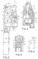
- the lock shown comprises in its structure a lower plate 1 and an upper plate 3, the latter extending so as to form a console 4 for supporting the electromechanical actuator.
- the operational components of the lock are housed mainly between the two plates 1 and 3.
- the components, as shown particularly in FIG. 3 include two hooking members 7, pivoting on pivots 6 supported by the plates 1 and 3.
- the hooking members are shown in the lock closing condition, and they are provided with springs (not shown) which push them towards the opening condition.
- the opening movement of the hooking members is prevented by a latch 9, which is pushed by a spring 8 and which can be removed, thus moving it away from the hooking members, by acting on a stud 10 with which it is provided. .
- This action is entrusted to an opening lever 12, pivoting on a pivot 11 supported by the plates 1 and 3, and having an lug 13 on which the exterior door opening handle acts, as well as an arm 14 with which cooperates with a lever 16, which is pivoted on a folded part 2 of the plate 1, and on which the interior door opening handle acts.
- the opening lever 12 is also provided with a second arm 15 intended to move the lock 9.
- the movement of the opening lever 12 can be transmitted to the bolt 10 of the lock 9 by a manual operating member 17 which presides over the safety locking of the lock, which is pivoted at 22 and which can be moved in the longitudinal direction to the illustrated position (blocking inserted) or even to a position moved down relative to FIG. 3 (blocking disinserted) under the action of a lever 21 pivoted on a folded part 5 of the plate 3 and connected to the manual operating member of the blocking (usually a pusher or a lever).
- the manual actuator 17 has a folded end 18 which in the disensed blocking condition cooperates with the arm 15 of the opening lever 12, a slot 19 in which engages the stud 10 of the bolt 9, and a subsequent slot of end 20 for electromechanical control.
- the folded end 18 of the member 17 does not interfere with the trajectory of the arm 15 of the opening lever 12, and therefore the opening lever moves empty and it cannot not open the door.
- the manual operating member 17 is moved downward, the folded end 18 faces the arm 15 of the opening lever 12, and therefore the operation of the latter causes the member 17, the stud 10, to move. and the latch 9, thus releasing the hooking members 7 which then, pushed by their springs, pass to the open position.
- an actuator 23 for electromechanical actuation, on the console 4 is mounted an actuator 23, described in more detail below, whose action is manifested by the displacement of an internal rod 43, protected by a bellows 25 and ending in a eyelet 24.
- a primary operating member 27 provided with two slots 28 in which engage guide studs 26 mounted on the plate 3.
- the member 27 has an appendage ending in a stud 29, which is engaged in the eyelet 24 of the actuator 23 and receives from the latter the movements controlled by the actuator.
- the member 27 is also provided with a finger 30 by means of which it can act on the same arm 14 of the opening lever 12, on which the lever 16 also controls the opening effected from the inside.
- the primary operating member 27 is provided with two flanges 31, 32 which support a secondary operating member 33 having an enlarged portion 34 which, for a direction of movement, bears against the flange 32. Between the flange 31 and the enlarged part 34 is disposed a spring 36 partially compressed.
- the secondary operating member 33 has a folded part 35 which engages in the slot 20 of the manual operating member 17.
- the primary operating member 27 has a rest position (to which it is renewed by the actuator 23 after each operation) which is that shown and in which the finger 30 faces the arm 12 of the opening lever 12 without acting on the latter; the slots 28 are arranged in such a way that, from this rest position, they allow the primary operating member 27: to move in one direction (the opening direction) so that the finger 30 acts on the arm 14 of the opening lever 12 for a long stroke, sufficient to give rise to the retraction of the latch 9 and therefore to the opening of the lock and of the door: as well as to move also in the opposite direction for a short stroke, corresponding to the operational stroke of the manual operating member 17.
- the folded part 35 of the secondary operating member 33 is arranged in such a way that, in this position of rest of the primary member of operation and if the manual operation member is in the inserted locking position (as shown), the folded part 35 is located near the outer end of the slot 20 of the manual operation member 17.
- the operation of the device is as follows.
- the actuator 23 could (unnecessarily, inadvertently this, because it is an operation with no effect) be actuated so as to move the primary operating member 27 in the direction opposite to the opening direction; in this case, the folded part 35 of the secondary operating member 33 would be limited to traversing, without effect, the length of the slot 20 of the manual operating member 17. If, on the contrary, at the time of actuation of the actuator 23 the manual operating member is in the release position of the blocking, it is moved to the position of insertion of the blocking, under the action of the folded part 35 of the secondary member of operation 33. The safety lock can therefore always be inserted, either manually or using the actuator 23.
- the actuator 23 can, on the contrary, be actuated in the direction which displaces the primary operating member 27 in the opening direction, and for an amplitude corresponding to the stroke of the manual operating member 17: in this case, the folded part 35 of the secondary operating member 33 carries with it the manual operating member 17 leading it to the condition of relaxation of the safety lock.
- the actuator 23 when the actuator 23 is actuated, the manual operating member is already in the release position of the blocking, the folded part 35 of the secondary operating member 33 is limited to traversing, without effect, the length of the slot 20 of the manual operating member 17.
- the safety lock can always be disinserted, either manually or by means of the actuator 23.
- the actuator 23 can be actuated in the direction which moves the primary operating member 27 in the opening direction, and for an amplitude corresponding to the stroke of the opening lever 12: in this case, in the first part of the stroke of the primary member 27, the folded part 35 of the secondary operating member 33 performs the operation, mentioned above, of bringing the manual operating member 17 to the relaxed position, if it is not there already, after which its contact with the outer end of the slot 20 prevents further movement of the secondary operating member 33.
- the subsequent travel of the primary operating member 27 is not prevented, since the flanges 31 and 32 can slide on the secondary maneuvering member 33 which is now immobile, by loading the spring 36.
- the opening lever 12 can be moved along its entire stroke, thereby giving rise to the opening of the lock and door.
- the actuator 23 is predisposed to always return the primary operating member 27 to its rest position after each operation, and in this circumstance the spring 36 is discharged again and the secondary operating member 33 resumes its initial position relative to the primary operating member 27.
- the actuator can carry out, from the rest position indicated by R, a short stroke in one direction (F1) to a position (B) of insertion the safety lock, then returning (F2) to the rest position R; or it can carry out, always from the rest position R, a short stroke in the opposite direction (F2) to a position (S) of relaxation of the safety lock, then returning (F4) to the position rest R; or, finally, the actuator can carry out, from the rest position R, a long stroke (F5) in the last direction mentioned, up to a position (A) for opening the lock and the door , then returning (F4) to the rest position R.
- the actuator 23 may comprise, as is particularly apparent from FIG. 4, an electric motor 37 with a pinion 38 which, through a chain of several reduction gears 40 (necessary to obtain the relatively high force necessary to actuate the opening lever 12), controls a toothed wheel 41 meshing with a rack 42 which is part of a rod 43 ending with the eyelet 24 already mentioned.
- the actuator also comprises an electromagnet 46, inserted electrically in parallel with the motor 37, and arranged to move away from a drum 39, supported by the axis of the motor 37, a braking pad 45 (FIG. 5) which normally is pushed by a spring 47 to brake the drum 39.
- This arrangement serves to ensure a rapid stop of the motor 37, and therefore of the rod, 42 when the electrical supply is interrupted. Otherwise, the high speed of the motor 37 could give rise to an additional stroke of the rod 42 and, consequently, to an imprecision in the final position given by the latter to the primary operating member 27.
- the start of the electrical supply to the actuator 23 for carrying out the various maneuvers provided can be controlled by means of a push-button or lever switch of any kind.
- the interruption of the supply when the intended positions have been reached, and the reversal of the supply for carrying out a return stroke, can be controlled by microswitches cooperating with the bodies concerned with the lock, but preferably the rod 42 of the actuator 23 has, in its internal part, at least one profiled slide 44 cooperating with microswitches 48 to perform this control action in the interior of the actuator 23, so as to simplify the structure and installation of the assembly.
- series of reduction gears 40 could be replaced by another reduction device, for example by a worm gear.
Landscapes
- Lock And Its Accessories (AREA)
Applications Claiming Priority (2)
| Application Number | Priority Date | Filing Date | Title |
|---|---|---|---|
| IT67066/86A IT1203528B (it) | 1986-01-28 | 1986-01-28 | Dispsositivo elettromeccanico per comandare il bloccaggio di sicurezza e l'apertura della porta di un veicolo |
| IT6706686 | 1986-01-28 |
Publications (3)
| Publication Number | Publication Date |
|---|---|
| EP0231042A2 true EP0231042A2 (de) | 1987-08-05 |
| EP0231042A3 EP0231042A3 (en) | 1988-10-05 |
| EP0231042B1 EP0231042B1 (de) | 1991-07-10 |
Family
ID=11299306
Family Applications (1)
| Application Number | Title | Priority Date | Filing Date |
|---|---|---|---|
| EP87200046A Expired - Lifetime EP0231042B1 (de) | 1986-01-28 | 1987-01-15 | Elektromechanische Betätigungsvorrichtung zum Verriegeln und Entriegeln von Kraftfahrzeugtüren |
Country Status (9)
| Country | Link |
|---|---|
| EP (1) | EP0231042B1 (de) |
| AR (1) | AR244378A1 (de) |
| BR (1) | BR8700270A (de) |
| DE (1) | DE3771223D1 (de) |
| ES (1) | ES2023883B3 (de) |
| IT (1) | IT1203528B (de) |
| PL (1) | PL154017B1 (de) |
| SU (1) | SU1600637A3 (de) |
| YU (1) | YU47254B (de) |
Cited By (16)
| Publication number | Priority date | Publication date | Assignee | Title |
|---|---|---|---|---|
| WO1994019569A1 (en) * | 1993-02-22 | 1994-09-01 | Jan Zikl | An apparatus for control of an extensible rod member of a safety system, in particular for locking a vehicle |
| GB2306552A (en) * | 1995-10-25 | 1997-05-07 | Rockwell Lvs | Vehicle door lock superlocking actuator |
| GB2307507A (en) * | 1995-11-24 | 1997-05-28 | Rockwell Lvs | Vehicle door lock actuator |
| FR2768869A1 (fr) * | 1997-09-22 | 1999-03-26 | Rockwell Lvs | Actionneur electrique de condamnation pour serrure de vehicule |
| FR2871186A1 (fr) * | 2004-06-07 | 2005-12-09 | Stremler Sa | Dispositif de verrouillage pour porte, fenetre ou porte-fenetre coulissante |
| WO2016061473A1 (en) * | 2014-10-16 | 2016-04-21 | Bruce Hagemeyer | Opposed hook sliding door lock |
| US9637957B2 (en) | 2012-11-06 | 2017-05-02 | Amesbury Group, Inc. | Automatically-extending remote door lock bolts |
| US9758997B2 (en) | 2008-12-19 | 2017-09-12 | Amesbury Group, Inc. | High security lock for door |
| US9765550B2 (en) | 2012-08-31 | 2017-09-19 | Amesbury Group, Inc. | Passive door lock mechanisms |
| US10662675B2 (en) | 2017-04-18 | 2020-05-26 | Amesbury Group, Inc. | Modular electronic deadbolt systems |
| US10808424B2 (en) | 2017-05-01 | 2020-10-20 | Amesbury Group, Inc. | Modular multi-point lock |
| US10968661B2 (en) | 2016-08-17 | 2021-04-06 | Amesbury Group, Inc. | Locking system having an electronic deadbolt |
| US11066850B2 (en) | 2017-07-25 | 2021-07-20 | Amesbury Group, Inc | Access handle for sliding doors |
| US11441333B2 (en) | 2018-03-12 | 2022-09-13 | Amesbury Group, Inc. | Electronic deadbolt systems |
| US11661771B2 (en) | 2018-11-13 | 2023-05-30 | Amesbury Group, Inc. | Electronic drive for door locks |
| US11834866B2 (en) | 2018-11-06 | 2023-12-05 | Amesbury Group, Inc. | Flexible coupling for electronic deadbolt systems |
Families Citing this family (1)
| Publication number | Priority date | Publication date | Assignee | Title |
|---|---|---|---|---|
| RU183598U1 (ru) * | 2018-03-06 | 2018-09-26 | Общество с ограниченной ответственностью "АТОС-ПРО" | Ригель электромагнитного замка |
Citations (3)
| Publication number | Priority date | Publication date | Assignee | Title |
|---|---|---|---|---|
| GB2045336A (en) * | 1979-03-26 | 1980-10-29 | Setec | Lock for Motor Vehicle Doors |
| FR2528098A1 (fr) * | 1982-06-02 | 1983-12-09 | Tack & Gabel | Fermeture de porte pour vehicule automobile |
| EP0159238A1 (de) * | 1984-03-20 | 1985-10-23 | Ecia - Equipements Et Composants Pour L'industrie Automobile | Elektromechanishe Schlossbedienung und Kraftfahrzeugtürschloss damit versehen |
-
1986
- 1986-01-28 IT IT67066/86A patent/IT1203528B/it active
- 1986-12-26 AR AR86306322A patent/AR244378A1/es active
-
1987
- 1987-01-15 ES ES87200046T patent/ES2023883B3/es not_active Expired - Lifetime
- 1987-01-15 DE DE8787200046T patent/DE3771223D1/de not_active Expired - Lifetime
- 1987-01-15 EP EP87200046A patent/EP0231042B1/de not_active Expired - Lifetime
- 1987-01-21 SU SU874028846A patent/SU1600637A3/ru active
- 1987-01-22 BR BR8700270A patent/BR8700270A/pt not_active IP Right Cessation
- 1987-01-27 YU YU11487A patent/YU47254B/sh unknown
- 1987-01-28 PL PL1987263854A patent/PL154017B1/pl unknown
Patent Citations (3)
| Publication number | Priority date | Publication date | Assignee | Title |
|---|---|---|---|---|
| GB2045336A (en) * | 1979-03-26 | 1980-10-29 | Setec | Lock for Motor Vehicle Doors |
| FR2528098A1 (fr) * | 1982-06-02 | 1983-12-09 | Tack & Gabel | Fermeture de porte pour vehicule automobile |
| EP0159238A1 (de) * | 1984-03-20 | 1985-10-23 | Ecia - Equipements Et Composants Pour L'industrie Automobile | Elektromechanishe Schlossbedienung und Kraftfahrzeugtürschloss damit versehen |
Cited By (24)
| Publication number | Priority date | Publication date | Assignee | Title |
|---|---|---|---|---|
| WO1994019569A1 (en) * | 1993-02-22 | 1994-09-01 | Jan Zikl | An apparatus for control of an extensible rod member of a safety system, in particular for locking a vehicle |
| GB2306552B (en) * | 1995-10-25 | 1999-11-17 | Rockwell Lvs | Vehicle door lock actuator |
| GB2306552A (en) * | 1995-10-25 | 1997-05-07 | Rockwell Lvs | Vehicle door lock superlocking actuator |
| US6089057A (en) * | 1995-10-25 | 2000-07-18 | Meritor Light Vehicle Systems (Uk) Lt. | Vehicle door lock actuator |
| GB2307507A (en) * | 1995-11-24 | 1997-05-28 | Rockwell Lvs | Vehicle door lock actuator |
| US5931034A (en) * | 1995-11-24 | 1999-08-03 | Meritor Light Vehicle Systems (Uk) Ltd. | Vehicle door lock actuator |
| GB2307507B (en) * | 1995-11-24 | 1999-09-01 | Rockwell Lvs | Vehicle door lock actuator |
| FR2768869A1 (fr) * | 1997-09-22 | 1999-03-26 | Rockwell Lvs | Actionneur electrique de condamnation pour serrure de vehicule |
| WO1999015748A1 (en) * | 1997-09-22 | 1999-04-01 | Meritor Light Vehicle Systems - France | Electric central-locking actuator for a vehicle |
| FR2871186A1 (fr) * | 2004-06-07 | 2005-12-09 | Stremler Sa | Dispositif de verrouillage pour porte, fenetre ou porte-fenetre coulissante |
| EP1605119A1 (de) * | 2004-06-07 | 2005-12-14 | Stremler | Verriegelungsanordnung für Tür, Fenster oder verschiebbare Fenstertür |
| US9758997B2 (en) | 2008-12-19 | 2017-09-12 | Amesbury Group, Inc. | High security lock for door |
| US9765550B2 (en) | 2012-08-31 | 2017-09-19 | Amesbury Group, Inc. | Passive door lock mechanisms |
| US9637957B2 (en) | 2012-11-06 | 2017-05-02 | Amesbury Group, Inc. | Automatically-extending remote door lock bolts |
| WO2016061473A1 (en) * | 2014-10-16 | 2016-04-21 | Bruce Hagemeyer | Opposed hook sliding door lock |
| US9790716B2 (en) | 2014-10-16 | 2017-10-17 | Amesbury Group, Inc. | Opposed hook sliding door lock |
| US10968661B2 (en) | 2016-08-17 | 2021-04-06 | Amesbury Group, Inc. | Locking system having an electronic deadbolt |
| US10662675B2 (en) | 2017-04-18 | 2020-05-26 | Amesbury Group, Inc. | Modular electronic deadbolt systems |
| US11634931B2 (en) | 2017-04-18 | 2023-04-25 | Amesbury Group, Inc. | Modular electronic deadbolt systems |
| US10808424B2 (en) | 2017-05-01 | 2020-10-20 | Amesbury Group, Inc. | Modular multi-point lock |
| US11066850B2 (en) | 2017-07-25 | 2021-07-20 | Amesbury Group, Inc | Access handle for sliding doors |
| US11441333B2 (en) | 2018-03-12 | 2022-09-13 | Amesbury Group, Inc. | Electronic deadbolt systems |
| US11834866B2 (en) | 2018-11-06 | 2023-12-05 | Amesbury Group, Inc. | Flexible coupling for electronic deadbolt systems |
| US11661771B2 (en) | 2018-11-13 | 2023-05-30 | Amesbury Group, Inc. | Electronic drive for door locks |
Also Published As
| Publication number | Publication date |
|---|---|
| YU47254B (sh) | 1995-01-31 |
| SU1600637A3 (ru) | 1990-10-15 |
| IT8667066A0 (it) | 1986-01-28 |
| BR8700270A (pt) | 1987-12-08 |
| IT1203528B (it) | 1989-02-15 |
| ES2023883B3 (es) | 1992-02-16 |
| PL263854A1 (en) | 1988-03-03 |
| AR244378A1 (es) | 1993-10-29 |
| EP0231042B1 (de) | 1991-07-10 |
| DE3771223D1 (de) | 1991-08-14 |
| YU11487A (en) | 1990-02-28 |
| PL154017B1 (en) | 1991-06-28 |
| EP0231042A3 (en) | 1988-10-05 |
Similar Documents
| Publication | Publication Date | Title |
|---|---|---|
| EP0231042B1 (de) | Elektromechanische Betätigungsvorrichtung zum Verriegeln und Entriegeln von Kraftfahrzeugtüren | |
| FR3060630B1 (fr) | Commande d'ouverture affleurante a ejection et retraction mecanique ou electrique. | |
| FR2639668A1 (fr) | Serrure electromecanique de porte | |
| FR2746718A1 (fr) | Vehicule automobile avec au moins une porte coulissante montee dans une paroi laterale | |
| EP0593371A1 (de) | Antrieb für einen Dreistellungsschalter | |
| FR2687717A1 (fr) | Fermeture de porte pour vehicules automobiles avec levier d'ouverture tendable. | |
| EP3581742A1 (de) | Motorbetriebene türgriffsteuerung und arbeitsweise | |
| EP0060175B1 (de) | Elektrische Verschliesseinrichtung für eine Kraftfahrzeughaube | |
| FR2766861A1 (fr) | Serrure de porte de vehicule automobile a condamnation electrique | |
| FR2800784A1 (fr) | Dispositif de commande d'un mecanisme de verrouillage d'une porte d'un vehicule | |
| FR2941994A1 (fr) | Dispositif de commande de l'ouverture d'un ouvrant et ouvrant de vehicule automobile equipe d'un tel dispositif | |
| FR2775717A1 (fr) | Dispositif d'ouverture/fermeture d'un ouvrant, notamment pour vehicule automobile | |
| EP0153234A1 (de) | Kupplungs- und Entkupplungsvorrichtung, insbesondere für einen Mechanismus zum elektrischen Versperren eines Kraftfahrzeugtürschlosses | |
| EP0304357B1 (de) | Verriegelbare Betätigungsvorrichtung mit Kabel für Kraftfahrzeugtürschloss | |
| FR2606448A1 (fr) | Serrure actionnee electriquement pour vehicule | |
| EP0269508A1 (de) | Motorisierte Schliessvorrichtung, insbesondere für Kofferraum oder Heckklappe eines Fahrzeuges | |
| EP0817227B1 (de) | Durch einen Elekromagnet verriegelbarer Sicherheitsschalter | |
| FR2579656A1 (fr) | Ensemble electronique de verrouillage des portes | |
| EP0270425A2 (de) | Schloss mit Antriebsritzel zwischen Rotor und Riegel | |
| FR2765611A1 (fr) | Dispositif d'ouverture d'une serrure de vehicule | |
| EP0170577A1 (de) | Bedienungsvorrichtung zum Öffnen von Kraftfahrzeugtürschlössern | |
| EP0906997A1 (de) | Verriegelungsvorrichtung mit einem nockenbetätigten Übertragungselement | |
| FR2971536A1 (fr) | Dispositif de commande de l'ouverture interieure d'un ouvrant a bouton poussoir et tendeur de cable. | |
| EP0230808B1 (de) | Verriegelungsvorrichtung für Kraftfahrzeugtürschloss | |
| FR2580321A1 (fr) | Serrure electrique condamnable, notamment pour vehicule automobile |
Legal Events
| Date | Code | Title | Description |
|---|---|---|---|
| PUAI | Public reference made under article 153(3) epc to a published international application that has entered the european phase |
Free format text: ORIGINAL CODE: 0009012 |
|
| AK | Designated contracting states |
Kind code of ref document: A2 Designated state(s): DE ES FR GB |
|
| PUAL | Search report despatched |
Free format text: ORIGINAL CODE: 0009013 |
|
| AK | Designated contracting states |
Kind code of ref document: A3 Designated state(s): DE ES FR GB |
|
| 17P | Request for examination filed |
Effective date: 19890317 |
|
| 17Q | First examination report despatched |
Effective date: 19890724 |
|
| RAP1 | Party data changed (applicant data changed or rights of an application transferred) |
Owner name: ROCKWELL AUTOMOTIVE BODY SYSTEMS ITALIANA S.P.A. |
|
| GRAA | (expected) grant |
Free format text: ORIGINAL CODE: 0009210 |
|
| AK | Designated contracting states |
Kind code of ref document: B1 Designated state(s): DE ES FR GB |
|
| REF | Corresponds to: |
Ref document number: 3771223 Country of ref document: DE Date of ref document: 19910814 |
|
| GBT | Gb: translation of ep patent filed (gb section 77(6)(a)/1977) | ||
| REG | Reference to a national code |
Ref country code: ES Ref legal event code: FG2A Ref document number: 2023883 Country of ref document: ES Kind code of ref document: B3 |
|
| PLBE | No opposition filed within time limit |
Free format text: ORIGINAL CODE: 0009261 |
|
| STAA | Information on the status of an ep patent application or granted ep patent |
Free format text: STATUS: NO OPPOSITION FILED WITHIN TIME LIMIT |
|
| 26N | No opposition filed | ||
| PGFP | Annual fee paid to national office [announced via postgrant information from national office to epo] |
Ref country code: FR Payment date: 19941230 Year of fee payment: 9 |
|
| PGFP | Annual fee paid to national office [announced via postgrant information from national office to epo] |
Ref country code: GB Payment date: 19950105 Year of fee payment: 9 |
|
| PGFP | Annual fee paid to national office [announced via postgrant information from national office to epo] |
Ref country code: ES Payment date: 19950119 Year of fee payment: 9 |
|
| PGFP | Annual fee paid to national office [announced via postgrant information from national office to epo] |
Ref country code: DE Payment date: 19950228 Year of fee payment: 9 |
|
| PG25 | Lapsed in a contracting state [announced via postgrant information from national office to epo] |
Ref country code: GB Effective date: 19960115 |
|
| PG25 | Lapsed in a contracting state [announced via postgrant information from national office to epo] |
Ref country code: ES Free format text: LAPSE BECAUSE OF NON-PAYMENT OF DUE FEES Effective date: 19960116 |
|
| GBPC | Gb: european patent ceased through non-payment of renewal fee |
Effective date: 19960115 |
|
| PG25 | Lapsed in a contracting state [announced via postgrant information from national office to epo] |
Ref country code: FR Effective date: 19960930 |
|
| PG25 | Lapsed in a contracting state [announced via postgrant information from national office to epo] |
Ref country code: DE Effective date: 19961001 |
|
| REG | Reference to a national code |
Ref country code: FR Ref legal event code: ST |
|
| REG | Reference to a national code |
Ref country code: ES Ref legal event code: FD2A Effective date: 19990503 |