EP0230800A1 - Mixing valve - Google Patents
Mixing valve Download PDFInfo
- Publication number
- EP0230800A1 EP0230800A1 EP86402615A EP86402615A EP0230800A1 EP 0230800 A1 EP0230800 A1 EP 0230800A1 EP 86402615 A EP86402615 A EP 86402615A EP 86402615 A EP86402615 A EP 86402615A EP 0230800 A1 EP0230800 A1 EP 0230800A1
- Authority
- EP
- European Patent Office
- Prior art keywords
- plate
- ball joint
- valve according
- valve
- center
- Prior art date
- Legal status (The legal status is an assumption and is not a legal conclusion. Google has not performed a legal analysis and makes no representation as to the accuracy of the status listed.)
- Granted
Links
Images


Classifications
-
- F—MECHANICAL ENGINEERING; LIGHTING; HEATING; WEAPONS; BLASTING
- F16—ENGINEERING ELEMENTS AND UNITS; GENERAL MEASURES FOR PRODUCING AND MAINTAINING EFFECTIVE FUNCTIONING OF MACHINES OR INSTALLATIONS; THERMAL INSULATION IN GENERAL
- F16K—VALVES; TAPS; COCKS; ACTUATING-FLOATS; DEVICES FOR VENTING OR AERATING
- F16K11/00—Multiple-way valves, e.g. mixing valves; Pipe fittings incorporating such valves
- F16K11/02—Multiple-way valves, e.g. mixing valves; Pipe fittings incorporating such valves with all movable sealing faces moving as one unit
- F16K11/06—Multiple-way valves, e.g. mixing valves; Pipe fittings incorporating such valves with all movable sealing faces moving as one unit comprising only sliding valves, i.e. sliding closure elements
- F16K11/078—Multiple-way valves, e.g. mixing valves; Pipe fittings incorporating such valves with all movable sealing faces moving as one unit comprising only sliding valves, i.e. sliding closure elements with pivoted and linearly movable closure members
- F16K11/0782—Single-lever operated mixing valves with closure members having flat sealing faces
-
- Y—GENERAL TAGGING OF NEW TECHNOLOGICAL DEVELOPMENTS; GENERAL TAGGING OF CROSS-SECTIONAL TECHNOLOGIES SPANNING OVER SEVERAL SECTIONS OF THE IPC; TECHNICAL SUBJECTS COVERED BY FORMER USPC CROSS-REFERENCE ART COLLECTIONS [XRACs] AND DIGESTS
- Y10—TECHNICAL SUBJECTS COVERED BY FORMER USPC
- Y10T—TECHNICAL SUBJECTS COVERED BY FORMER US CLASSIFICATION
- Y10T137/00—Fluid handling
- Y10T137/8593—Systems
- Y10T137/86493—Multi-way valve unit
- Y10T137/86549—Selective reciprocation or rotation
-
- Y—GENERAL TAGGING OF NEW TECHNOLOGICAL DEVELOPMENTS; GENERAL TAGGING OF CROSS-SECTIONAL TECHNOLOGIES SPANNING OVER SEVERAL SECTIONS OF THE IPC; TECHNICAL SUBJECTS COVERED BY FORMER USPC CROSS-REFERENCE ART COLLECTIONS [XRACs] AND DIGESTS
- Y10—TECHNICAL SUBJECTS COVERED BY FORMER USPC
- Y10T—TECHNICAL SUBJECTS COVERED BY FORMER US CLASSIFICATION
- Y10T137/00—Fluid handling
- Y10T137/8593—Systems
- Y10T137/86493—Multi-way valve unit
- Y10T137/86815—Multiple inlet with single outlet
Definitions
- the invention relates to a mixing valve for mixing two flows and more particularly intended for the sanitary field, for mixing hot water and cold water.
- the invention relates more particularly to the field of valves of a particular type where the elements producing the mixture are ceramic plates having polished surfaces in contact and movable relative to one another.
- the ceramic plates generally have duct elements communicating from one plate to the other, so that the passage section of the two flows is made adjustable before their actual mixing, by the positioning of the two plates.
- Known systems very generally comprise a fixed ceramic plate and a movable ceramic plate, the position of which is varied by means of a single lever-shaped control, movable in two movements corresponding respectively, for the user, to the adjustment the flow of mixed water and the adjustment of the ratio of the two flows in said mixture.
- a first object of the invention is to propose a valve with polished plates, actuated by a single lever and the two settings of which are truly independent.
- the known devices are provided with plates pierced in such a way that, for the most part, the two flows of hot and cold water pass through the fixed plate, mix at the level of the mobile plate without passing through it and this mixture being evacuated to an outlet substantially parallel to the two inlets, generally via an additional orifice in the fixed plate.
- This path of the water in the valve and in particular the complete change of direction which takes place between the fixed and mobile plates, is very generally the cause of relatively annoying operating noises, so that many valves of this kind are provided anti-noise screen, which also has the major disadvantage of clog very quickly.
- Another object of the invention is to provide a device having a low level of operating noise, without a screen, in particular due to the fact that the mixed water can be discharged laterally along the contour of the movable plate, which does not include no duct element, the characteristics of the two settings of flow and mixing respectively, being obtained by the very shape of said contour.
- the invention essentially relates to a mixing valve for mixing two flows, comprising a body containing two plates each having a flat and smooth face, these flat faces being in contact with one another, one plates being fixed and having two orifices respectively in communication with inlet conduits of the two flows and the other plate being movable and coupled to a ball joint lever, a lateral outlet being arranged in the vicinity of the edge of the movable plate, characterized in that said ball joint lever is subject to move in a predetermined pivoting direction defined by a fixed guide groove with respect to said body, with the possibility of rotation on its axis, of a predetermined amplitude for any position the along said pivoting direction, the two extreme positions of rotation being determined by at least one stop of said lever cooperating with the edges of said groove re and in that said movable plate, coupled to said ball joint lever by an offset offset thereof, has the approximate shape of a trapezoid with rounded ends.
- the plates defined above are preferably ceramic plates or "mirrors" respectively comprising smooth surfaces in contact to ensure the distribution and the mixing of the two aforementioned flows. It is quite obvious, however, that the invention in fact covers any wafer device whose shapes and mounting correspond to the above definition, even if these wafers are not made of ceramic, but of a material whose state of surface and mechanical characteristics make it possible to obtain results which are substantially equivalent, or even worse, in terms of sealing on closing, in particular.
- said rounded ends are portions of circles, the radii and the positions of these circles being deduced from the "kinematics" imposed on the movable plate by the aforementioned rotary lever, as will appear clearly further.
- a mixing valve 11 comprising a body 12, for example of molded plastic, intended to be inserted into a suitable cavity of a tap 13 sketched in phantom in Figure 2.
- the two hot and cold water flows are respectively introduced into the body by two inlets 14 and 15 located at the lower part of the body (considering figure 2), while a wide lateral outlet 16 of mixed water s opens next to the tap outlet duct 13.
- the valve body 12 is shaped to present, at its upper part, a guide groove curve 17 opening into a portion of cavity 18a with a spherical surface, provided for the articulation of a ball joint lever 19.
- the body 12 furthermore houses and in order, said ball joint lever 19, engaged in the groove 17, an internal base 20, fixed inside said body and shaped in particular to define the other portion of cavity 18b with a spherical surface in which the ball joint 19a of the lever 19 is articulated, a coupling part 22 with a thin wall, made of material self-lubricating, an operating plate 23, a movable plate 24 in ceramic, a fixed plate 25 in ceramic, and a bottom wall 26 fixed to said body and comprising in its thickness two holes for the cold water and Hot water.
- Each hole houses a metal connection ring 28, surrounded by a tubular seal 29 made of rubber or equivalent elastomeric material.
- the "ceramic" of the plates 24 and 25 is, preferably alumina oxide; the shape of the plates is obtained by sintering.
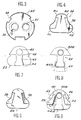
- the fixed plate 25 has approximately the shape of a disc comprising, along its circular edge, notches 32 cooperating with internal lateral projections of said body 12, for the immobilization of said fixed plate in said body.
- the seals 29 are applied in a sealed manner around the lower orifices of two inclined conical holes 35 extending in the thickness of the fixed plate 25 and whose upper circular orifices 30 and 31 (respectively for hot water and the cold water) open onto the smooth face of the movable plate 24.
- the two orifices 30 and 31 are spaced apart by a chosen distance and have a predetermined diameter. As will be seen later, this spacing distance and this diameter are important parameters in determining the shape and dimensions of the movable plate.
- the movable plate 24 is in contact by its smooth face shown in Figure 4 with the fixed plate 25 shown in Figure 3. It has no drilling.
- the variable closure of the orifices 30 and 31 is determined by the special contour of the plate 24.
- the opposite face of the latter (FIG. 5) has a relief defined by two lateral clearances 38.
- a complementary relief materialized by two embedding cheeks 39 is formed on the maneuvering plate 23.
- the latter made of molded plastic, thus naturally fits onto the movable plate 24.
- the maneuvering plate has a cavity 40 in which is engaged a projection 42 projecting from the lower part of the ball 19a.
- the projection 41 is offset with respect to the lever 19.
- the face 42 of the maneuvering plate 23 opposite the movable plate has a guide rib 43 provided with a rounded enlargement 44 engaged in a fixed groove 45 defined on the lower face ( always considering FIG. 2) of the internal base 20.
- the coupling piece 22 (made of plastic loaded with molybdenum bisulfite) is shaped to cover the edges and the internal wall of the cavity 40, as well as the rib 43 and its widening rounded 44, in particular the sides thereof. To this end, it comprises a tubular portion 40a and a skirt 44a with a curved profile.
- the sides of the operating plate 23 have cantilevered surfaces 46, extending the embedding cheeks 39.
- the ball joint lever 19 is subject to move in a predetermined pivoting direction defined by the groove 17, the pivot center being that of the ball joint 19a.
- the lever is also mounted with the possibility of rotation on its axis, of a predetermined amplitude, for each of its positions along said groove.
- the lever 19 has a double stop 50, in the form of a cam, engaged in the thickness of the groove 17 and capable of coming into contact with the sides of the latter. The two extreme positions of rotation of the lever on itself are thus determined when the double stop 50 comes into contact with the sides of the groove 17.
- the eccentric projection 41 is located substantially in a plane of symmetry of the stop 50. It crosses a lower window 52 of the internal base 20 for transmitting its movement to the movable plate 24 via the maneuvering plate 23. Under these conditions, the end of the projection 41 can occupy any position in a surface delimited by a contour 53 represented in dashed lines in FIGS. 9a to 9c, the contour 53 itself corresponding to at least one extreme position (in rotation or in pivoting according to the definitions above) of the ball joint lever 19.
- the pivoting movement (along the groove 17) controls the flow of water at the outlet 16, while the rotary movement of the lever on its axis controls the mixing of hot water and water cold.
- the face of the movable plate 24 in contact with the fixed plate 25 has the approximate shape of a "trapezoid" with rounded ends (see FIG. 4). Said rounded ends are more particularly portions of circles, since the orifices 30 and 31 which they must cover in certain positions are also circular. Of course, if the orifices 30 and 31 were to have a different shape, for example ovalized, the rounded ends of said trapezium would not necessarily be circles, and the invention covers all these possible variants.
- FIGS. 9a to 9d it appears that the outline of the entire lower part of the "trapezoid” is linked to the spacing and to the diameter of the orifices 30 and 31. More precisely, the center of the portion of the circle defining each end A1 or A2 of the widest base of the "trapezoid” is placed to be substantially superimposed on the center of one (30, figure 9b) of the two orifices of the fixed plate when the ball joint lever is placed at the end of the groove 17 which corresponds to the closing of the valve and in an extreme position of rotation on itself, respectively. In FIG. 9b, this particular position of the ball joint lever is such that the eccentric projection 41 is at A on the contour 53. It can be seen that under these conditions and considering FIG.
- FIGS. 9a and 9b illustrate two configurations for closing the valve.
- the valve is closed in the position of equal mixing of the two flows, while in FIG. 9d the valve is closed in the position of maximum selection of one of the two flows (here hot water).
- each edge of said movable plate 24 between the two bases of said "trapezoid” has a portion of a circle C1 or C2 arranged so that, for each of the two extreme pivoting positions of said ball joint lever placed at the end of said guide groove which corresponds to the closing of the valve (FIG. 9b), the center of the other (31) of the two orifices is substantially coincident with the center of one of these circle portions (C), respectively.
- the circle portion C2 improves the closing seal of the orifice 31.
- the circular portion C1 improves the tightness of the obturation of the orifice 30.
- the center of the portion of circle defining each end B1 or B2 of the shortest base of said trapezium is placed to be substantially superimposed on the center of one (30, FIG. 9d ) of the two orifices of the fixed plate when said ball joint lever is placed at the end of the guide groove 17 which corresponds to the maximum opening of the valve and in an extreme position of rotation itself, respectively.
- this particular position of the ball joint lever is such that the projection 41 is at B on the contour 53. It can be seen that under these conditions, the rounded end B1 of the small base of the trapezium more particularly covers the orifice 30.
- FIGS. 9c and 9d illustrate two configurations for maximum opening of the valve.
- the valve is open as much as possible in the position of equal mixing of the two flows, while in FIG. 9b, the valve is completely open in the position of maximum selection of one of the two flows, cold).
Landscapes
- Engineering & Computer Science (AREA)
- General Engineering & Computer Science (AREA)
- Mechanical Engineering (AREA)
- Multiple-Way Valves (AREA)
- Valve-Gear Or Valve Arrangements (AREA)
- Feeding And Controlling Fuel (AREA)
- Fluid-Driven Valves (AREA)
- Sliding Valves (AREA)
- Valve Housings (AREA)
- Curing Cements, Concrete, And Artificial Stone (AREA)
- Compositions Of Macromolecular Compounds (AREA)
- Solid-Sorbent Or Filter-Aiding Compositions (AREA)
Abstract
Description
L'invention se rapporte à une vanne mitigeuse pour le mélange de deux flux et plus particulièrement destinée au domaine sanitaire, pour le mélange de l'eau chaude et de l'eau froide. L'invention concerne plus particulièrement le domaine des vannes d'un type particulier où les éléments réalisant le mélange sont des plaquettes de céramique comportant des surfaces polies en contact et déplaçables l'une par rapport à l'autre.The invention relates to a mixing valve for mixing two flows and more particularly intended for the sanitary field, for mixing hot water and cold water. The invention relates more particularly to the field of valves of a particular type where the elements producing the mixture are ceramic plates having polished surfaces in contact and movable relative to one another.
Les vannes dites mitigeuses, à plaquettes de céramique (oxyde d'alumine fritté) encore appelées "glaces" en raison de leurs surfaces lisses en contact mutuel, sont de plus en plus appréciées dans le domaine de la robinetterie sanitaire. Les plaquettes de céramique comportent, le plus souvent, des éléments de conduit communiquant d'une plaquette à l'autre, de sorte que la section de passage des deux flux soit rendue ajustable avant leur mélange proprement dit, par le positionnement des deux plaquettes. Les systèmes connus comportent très généralement une plaquette de céramique fixe et une plaquette de céramique mobile, dont on fait varier la position au moyen d'une commande unique en forme de levier, mobile selon deux mouvements correspondant respectivement, pour l'utilisateur, au réglage du débit d'eau mélangée et au réglage du rapport des deux flux dans ledit mélange.Valves called mixing valves, with ceramic plates (sintered alumina oxide) also called "glass" because of their smooth surfaces in mutual contact, are more and more appreciated in the field of sanitary tapware. The ceramic plates generally have duct elements communicating from one plate to the other, so that the passage section of the two flows is made adjustable before their actual mixing, by the positioning of the two plates. Known systems very generally comprise a fixed ceramic plate and a movable ceramic plate, the position of which is varied by means of a single lever-shaped control, movable in two movements corresponding respectively, for the user, to the adjustment the flow of mixed water and the adjustment of the ratio of the two flows in said mixture.
Jusqu'à présent, tous les systèmes proposés sont tels que l'arc de réglage du mélange décrit à plein débit d'eau mélangée,est inférieur à celui qui est décrit aux faibles débits. Par conséquent, les efforts de manoeuvre et la sensibilité de réglage ne sont pas constants suivant la position du levier en débit. La modification de l'un des réglages se répercute plus ou moins sur l'autre.Until now, all the systems proposed have been such that the arc for adjusting the mixture described at full flow of mixed water is less than that which is described at low flows. Consequently, the operating forces and the adjustment sensitivity are not constant depending on the position of the lever in flow. The modification of one of the settings affects more or less the other.
Un premier objet de l'invention est de proposer une vanne à plaquettes polies, actionnée par un levier unique et dont les deux réglages soient réellement indépendants.A first object of the invention is to propose a valve with polished plates, actuated by a single lever and the two settings of which are truly independent.
Par ailleurs,les dispositifs connus sont pourvus de plaquettes percées de telle façon que,pour la plupart, les deux flux d'eau chaude et froide traversent la plaquette fixe,se mélangent au niveau de la plaquette mobile sans la traverser et que ce mélange soit évacué vers une sortie sensiblement parallèle aux deux entrées, généralement par un orifice supplémentaire de la plaquette fixe. Ce cheminement de l'eau dans la vanne et notamment le changement complet de direction qui s'opère entre les plaquettes fixe et mobile, est très généralement la cause de bruits de fonctionnement relativement gênants, de sorte que de nombreuses vannes de ce genre sont pourvues de tamis anti-bruit, qui présent par ailleurs l'inconvénient majeur de s'obstruer très rapidement. Un autre but de l'invention est de proposer un dispositif présentant un faible niveau de bruit de fonctionnement, sans tamis, notamment en raison du fait que l'eau mélangée peut être évacuée latéralement le long du contour de la plaquette mobile, laquelle ne comporte aucun élément de conduit, les caractéristiques des deux réglages respectivement de débit et de mélange, étant obtenues par la forme même dudit contour.Furthermore, the known devices are provided with plates pierced in such a way that, for the most part, the two flows of hot and cold water pass through the fixed plate, mix at the level of the mobile plate without passing through it and this mixture being evacuated to an outlet substantially parallel to the two inlets, generally via an additional orifice in the fixed plate. This path of the water in the valve and in particular the complete change of direction which takes place between the fixed and mobile plates, is very generally the cause of relatively annoying operating noises, so that many valves of this kind are provided anti-noise screen, which also has the major disadvantage of clog very quickly. Another object of the invention is to provide a device having a low level of operating noise, without a screen, in particular due to the fact that the mixed water can be discharged laterally along the contour of the movable plate, which does not include no duct element, the characteristics of the two settings of flow and mixing respectively, being obtained by the very shape of said contour.
Dans cet esprit, l'invention concerne essentiellement une vanne mitigeuse pour le mélange de deux flux, comprenant un corps renfermant deux plaquettes comportant chacune une face plane et lisse, ces faces planes étant en contact l'une contre l'autre, l'une des plaquettes étant fixe et comportant deux orifices respectivement en communication avec des conduits d'entrée des deux flux et l'autre plaquette étant mobile et couplée à un levier à rotule, une sortie latérale étant agencée au voisinage de la bordure de la plaquette mobile, caractérisée en ce que ledit levier à rotule est assujetti à se déplacer suivant une direction de pivotement pré-déterminée définie par une rainure de guidage fixe par rapport audit corps, avec possibilité de rotation sur son axe, d'une amplitude prédéterminée pour toute position le long de ladite direction de pivotement, les deux positions extrêmes de rotation étant déterminées par au moins une butée dudit levier coopérant avec les bords de ladite rainure et en ce que ladite plaquette mobile, couplée audit levier à rotule par une projection désaxée de celui-ci, a la forme approximative d'un trapèze aux extrémités arrondies.In this spirit, the invention essentially relates to a mixing valve for mixing two flows, comprising a body containing two plates each having a flat and smooth face, these flat faces being in contact with one another, one plates being fixed and having two orifices respectively in communication with inlet conduits of the two flows and the other plate being movable and coupled to a ball joint lever, a lateral outlet being arranged in the vicinity of the edge of the movable plate, characterized in that said ball joint lever is subject to move in a predetermined pivoting direction defined by a fixed guide groove with respect to said body, with the possibility of rotation on its axis, of a predetermined amplitude for any position the along said pivoting direction, the two extreme positions of rotation being determined by at least one stop of said lever cooperating with the edges of said groove re and in that said movable plate, coupled to said ball joint lever by an offset offset thereof, has the approximate shape of a trapezoid with rounded ends.
Bien entendu, dans l'état actuel de la technique, les plaquettes définies ci-dessus sont de préférence des plaquettes en céramique ou "glaces" comportant respectivement des surfaces lisses en contact pour assurer la distribution et le mélange des deux flux précités. Il est bien évident, cependant, que l'invention couvre en fait tout dispositif à plaquette dont les formes et le montage correspondent à la définition qui précède, même si ces plaquettes ne sont pas en céramique, mais dans un matériau dont l'état de surface et les caractéristiques mécaniques permettent d'obtenir des résultats sensiblement équivalents, voire moins bons, sur le plan de l'étanchéité à la fermeture, notamment.Of course, in the current state of the art, the plates defined above are preferably ceramic plates or "mirrors" respectively comprising smooth surfaces in contact to ensure the distribution and the mixing of the two aforementioned flows. It is quite obvious, however, that the invention in fact covers any wafer device whose shapes and mounting correspond to the above definition, even if these wafers are not made of ceramic, but of a material whose state of surface and mechanical characteristics make it possible to obtain results which are substantially equivalent, or even worse, in terms of sealing on closing, in particular.
Selon une autre caractétistique notable de l'invention, lesdites extrémités arrondies sont des portions de cercles, les rayons et les positions de ces cercles étant déduits de la "cinématique" imposée à la plaquette mobile par le levier à roture précité, comme cela apparaîtra clairement plus loin.According to another notable characteristic of the invention, said rounded ends are portions of circles, the radii and the positions of these circles being deduced from the "kinematics" imposed on the movable plate by the aforementioned rotary lever, as will appear clearly further.
L'invention sera mieux comprise et d'autres avantages de celle-ci apparaîtront plus clairement à la lumière de la description qui va suivre d'un mode de réalisation actuellement préféré d'une vanne mitigeuse conforme à son principe, donnée uniquement à titre d'exemple et faite en référence aux dessins annexés, dans lesquels :
- - la figure 1 est une vue en perspective éclatée des éléments constitutifs de la vanne;
- - la figure 2 est une vue en coupe et avec arrachement partiel de la vanne, montée;
- - la figure 3 représente la plaquette fixe et plus particulièrement sa face en contact avec ladite plaquette mobile;
- - la figure 4 représente la plaquette mobile et plus particulièrement sa face en contact avec ladite plaquette fixe;
- - la figure 5 représente la plaquette mobile et plus particulièrement l'autre face de celle-ci;
- - la figure 6 représente une plaquette de manoeuvre de la plaquette mobile et plus particulièrement la face de celle-ci qui s'emboîte dans ladite plaquette mobile, une pièce de couplage auto-lubrifiante étant également représentée en place de l'autre côté de ladite plaquette de manoeuvre;
- - la figure 7 représente la même plaquette de manoeuvre vue du côté opposé à celui de la figure 6;
- - la figure 8 représente la pièce de couplage de la figure 6, vue du côté qui s'emboîte dans ladite plaquette de manoeuvre; et
- - les figures 9a à 9c illustrent schématiquement, par leurs contours les plaquettes fixe et mobile dans les positions relatives qu'elles occupent pour quatre positions remarquables du levier à rotule qui commande la plaquette mobile.
- - Figure 1 is an exploded perspective view of the components of the valve;
- - Figure 2 is a sectional view with partial cutaway of the valve, mounted;
- - Figure 3 shows the fixed plate and more particularly its face in contact with said movable plate;
- - Figure 4 shows the movable plate and more particularly its face in contact with said fixed plate;
- - Figure 5 shows the movable plate and more particularly the other side thereof;
- - Figure 6 shows an operating plate of the movable plate and more particularly the face thereof which fits into said movable plate, a self-lubricating coupling part also being shown in place on the other side of said maneuvering plate;
- - Figure 7 shows the same operating plate seen from the side opposite to that of Figure 6;
- - Figure 8 shows the coupling part of Figure 6, seen from the side which fits into said maneuvering plate; and
- - Figures 9a to 9c schematically illustrate, by their contours the fixed and movable plates in the relative positions they occupy for four remarkable positions of the ball joint lever which controls the mobile plate.
En se reportant aux dessins, on a représenté une vanne mitigeuse 11, comportant un corps 12, par exemple en matière plastique moulée, destiné à être inséré dans une cavité adaptée d'un robinet 13 esquissé en traits mixtes sur la figure 2. Les deux flux d'eau chaude et d'eau froide sont respectivement introduits dans le corps par deux entrées 14 et 15 situées à la partie inférieure du corps (en considérant la figure 2), tandis qu'une large sortie latérale 16 d'eau mélangée s'ouvre en regard du conduit de sortie du robinet 13.Comme le montrent les fig. 1 et 2, le corps de vanne 12 est conformé pour présenter, à sa partie supérieure, une rainure de guidage courbe 17 débouchant dans une portion de cavité 18a à surface sphérique, prévue pour l'articulation d'un levier à rotule 19. Le corps 12 abrite en outre et dans l'ordre, ledit levier à rotule 19, engagé dans la rainure 17, un socle interne 20, fixe à l'intérieur dudit corps et conformé notamment pour définir l'autre portion de cavité 18b à surface sphérique dans laquelle s'articule la rotule 19a du levier 19, une pièce de couplage 22 à paroi mince, en matériau auto-lubrifiant, une plaquette de manoeuvre 23, une plaquette mobile 24 en céramique, une plaquette fixe 25 en céramique, et une paroi de fond 26 fixée audit corps et comportant dans son épaisseur deux perçages pour les arrivées d'eau froide et d'eau chaude. Chaque perçage abrite une bague de raccordement 28 métallique, entourée d'un joint d'étanchéité tubulaire 29 en caoutchouc ou matériau élastomère équivalent. Cet agencement définit ainsi l'entrée d'eau chaude 14 et l'entrée d'eau froide 15, à l'extrémité inférieure du corps de vanne formée par la paroi de fond 26. La "céramique" des plaquettes 24 et 25 est, de préférence, de l'oxyde d'alumine; la forme des plaquettes est obtenue par frittage. La plaquette fixe 25 a approximativement la forme d'un disque comportant,le long de son bord circulaire, des entailles 32 coopérant avec des saillies latérales internes dudit corps 12, pour l'immobilisation de ladite plaquette fixe dans ledit corps. Les joints 29 s'appliquent de façon étanche autour des orifices inférieurs de deux perçages coniques inclinés 35 s'étendant dans l'épaisseur de la plaquette fixe 25 et dont les orifices circulaires supérieurs 30 et 31 (respectivement pour l'eau chaude et l'eau froide) débouchent sur la face lisse de la plaquette mobile 24. Les deux orifices 30 et 31 sont écartés d'une distance choisie et ont un diamètre prédéterminé. Comme on le verra plus loin, cette distance d'écartement et ce diamètre sont des paramètres importants dans la détermination de la forme et des dimensions de la plaquette mobile.Referring to the drawings, there is shown a
La plaquette mobile 24 est en contact par sa face lisse représentée à la figure 4 avec la plaquette fixe 25 représentée à la figure 3. Elle ne comporte aucun perçage. L'obturation variable des orifices 30 et 31 est déterminée par le contour spécial de la plaquette 24. La face opposée de cette dernière (figure 5) comporte un relief défini par deux dégagements latéraux 38. Un relief complémentaire matérialisé par deux joues d'encastrement 39 est formé sur la plaquette de manoeuvre 23. Cette dernière, en matière plastique moulée, s'emboîte ainsi naturellement sur la plaquette mobile 24. La plaquette de manoeuvre comporte une cavité 40 dans laquelle est engagée une projection 42 faisant saillie à la partie inférieure de la rotule 19a. La projection 41 est désaxée par rapport au levier 19. La face 42 de la plaquette de manoeuvre 23 opposée à la plaquette mobile comporte une nervure de guidage 43 munie d'un élargissement arrondi 44 engagé dans une gorge fixe 45 définie à la face inférieure (toujours en considérant la figure 2) du socle interne 20. La pièce de couplage 22 (en matière plastique chargée de bisulfite de molybdène) est conformée pour recouvrir les bords et la paroi interne de la cavité 40, ainsi que la nervure 43 et son élargissement arrondi 44, notamment les flancs de celui-ci. Elle comporte à cet effet une portion tubulaire 40a et une jupe 44a à profil bombé. De plus, les flancs de la plaquette de manoeuvre 23 comportent des surfaces en encorbellement 46, prolongeant les joues d'encastrement 39. Cette particularité de structure constitue un déflecteur pour l'eau sortant des orifices 30 et 31, ce qui facilite l'écoulement silencieux de l'eau vers la sortie latérale 16, tout en évitant les phénomènes de cavitation. Selon une particularité importante de l'invention, le levier à rotule 19 est assujetti à se déplacer suivant une direction de pivotement prédéterminée définie par la rainure 17, le centre de pivotement étant celui de la rotule 19a. Le levier est en outre monté avec possibilité de rotation sur son axe, d'une amplitude prédéterminée, pour chacune de ses positions le long de ladite rainure. Pour ce faire, le levier 19 comporte une double butée 50, en forme de came, engagée dans l'épaisseur de la rainure 17 et susceptible d'entrer en contact avec les flancs de celle-ci. Les deux positions extrêmes de rotation du levier sur lui-même sont ainsi déterminées lorsque la double butée 50 entre en contact avec les flancs de la rainure 17. La projection excentrée 41 se situe sensiblement dans un plan de symétrie de la butée 50. Elle traverse une fenêtre inférieure 52 du socle interne 20 pour transmettre son mouvement à la plaquette mobile 24 via la plaquette de manoeuvre 23. Dans ces conditions, l'extrémité de la projection 41 peut occuper n'importe quelle position dans une surface délimitée par un contour 53 représenté en traits mixtes sur les figures 9a à 9c, le contour 53 lui-même correspondant à au moins une position extrême (en rotation ou en pivotement suivant les définitions qui précèdent) du levier à rotule 19.The
Bien entendu, le mouvement de pivotement (le long de la rainure 17) commande le débit d'eau à la sortie 16, tandis que le mouvement de rotation du levier sur son axe commande le mélange de l'eau chaude et de l'eau froide.Of course, the pivoting movement (along the groove 17) controls the flow of water at the
On conçoit que, grâce à la conception et au montage du levier à rotule, conformément à la description qui précède, les deux mouvements de réglage soient totalement indépendants, puisque, pour toute position de pivotement du levier, l'amplitude de rotation de ce même levier est constante et déterminée par la butée 50 et la rainure 17.It is understood that, thanks to the design and mounting of the ball joint lever, in accordance with the above description, the two adjustment movements are completely independent, since, for any pivoting position of the lever, the amplitude of rotation of this same lever is constant and determined by the
Selon une caractéristique importante de l'invention, la face de la plaquette mobile 24 en contact avec la plaquette fixe 25 a la forme approximative d'un "trapèze" aux extrémités arrondies (voir figure 4). Lesdites extrémités arrondies sont plus particulièrement des portions de cercles, puisque les orifices 30 et 31 qu'elles doivent recouvrir dans certaines positions sont aussi circulaires. Bien entendu, si les orifices 30 et 31 devaient avoir une forme différente, par exemple ovalisée, les extrémités arrondies dudit trapèze ne seraient pas obligatoirement des cercles, et l'invention couvre toutes ces variantes d'exécution possibles.According to an important characteristic of the invention, the face of the
Considérant plus particulièrement les figures 9a à 9d, il apparaît que le contour de toute la partie inférieure du "trapèze" est liée à l'écartement et au diamètre des orifices 30 et 31. Plus précisément, le centre de la portion de cercle définissant chaque extrémité A₁ ou A₂ de la base la plus large du "trapèze" est placé pour être sensiblement superposé au centre de l'un (30, figure 9b) des deux orifices de la plaquette fixe lorsque le levier à rotule est placé à l'extrémité de la rainure 17 qui correspond à la fermeture de la vanne et dans une position extrême de rotation sur lui-même, respectivement. Sur la figure 9b, cette position particulière du levier à rotule est telle que la projection excentrée 41 se trouve en A sur le contour 53. On voit que dans ces conditions et en considérant la figure 9b, l'extrémité arrondie A₁ de la grande base du trapèze recouvre plus particulièrement l'orifice 30. Lorsque le levier à rotule est dans l'autre position possible définie ci-dessus, l'autre extrémité arrondie A₂de la grande base du trapèze recouvre plus particulièrement l'orifice 31 et la projection désaxée 41 se trouve alors en Aʹ sur le contour 53. Les figures 9a et 9b illustrent deux configurations de fermeture de la vanne. Sur la figure 9a, la vanne est fermée en position de mélange égal des deux flux, alors que sur la figure 9d la vanne est fermée en position de sélection maximum de l'un des deux flux (ici l'eau chaude).Considering more particularly FIGS. 9a to 9d, it appears that the outline of the entire lower part of the "trapezoid" is linked to the spacing and to the diameter of the
En outre, chaque bord de ladite plaquette mobile 24 comprise entre les deux bases dudit "trapèze" comporte une portion de cercle C₁ ou C₂ disposée pour que, pour chacune des deux positions extrêmes de pivotement dudit levier à rotule placé à l'extrémité de ladite rainure de guidage qui correspond à la fermeture de la vanne (figure 9b), le centre de l'autre (31) des deux orifices soit sensiblement confondu avec le centre de l'une de ces portions de cercle (C ), respectivement. On voit que dans cette position de fermeture de la vanne pour laquelle la projection désaxée est en A, la portion de cercle C₂ améliore l'étanchéité de fermeture de l'orifice 31. Dans l'autre position de fermeture symétrique pour laquelle la projection désaxée se trouve en Aʹ, la ortion de cercle C₁ améliore l'étanchéité de l'obturation de l'orifice 30.In addition, each edge of said
De façon analogue à ce qui a été décrit plus haut, le centre de la portion de cercle définissant chaque extrémité B₁ ou B₂ de la base la plus courte dudit trapèze est placée pour être sensiblement superposée au centre de l'un (30, figure 9d) des deux orifices de la plaquette fixe lorsque ledit levier à rotule est placé à l'extrémité de la rainure de guidage 17 qui correspond à l'ouverture maximum de la vanne et dans une position extrême de rotation suir lui-même, respectivement. Sur la figure 9d, cette position particulière du levier à rotule est telle que la projection 41 se trouve en B sur le contour 53. On voit que dans ces conditions, l'extrémité arrondie B₁ de la petite base du trapèze recouvre plus particulièrement l'orifice 30. Lorsque le levier à rotule est dans l'autre position possible de mélange pour l'ouverture maximum, l'autre extremité arrondie B² de la petite base du trapèze recouvre plus particulièrement l'orifice 31 et la projection désaxée se trouve en Bʹ sur le contour 53. Les figures 9c et 9d illustrent deux configurations d'ouverture maximum de la vanne. Sur la figure 9c, la vanne est ouverte au maximum en position de mélange égal des deux flux, alors que sur la figure 9b, la vanne est totalement ouverte en position de sélection maximum de l'un des deux flux, (ici l'eau froide).Analogously to what has been described above, the center of the portion of circle defining each end B₁ or B₂ of the shortest base of said trapezium is placed to be substantially superimposed on the center of one (30, FIG. 9d ) of the two orifices of the fixed plate when said ball joint lever is placed at the end of the
Il apparaît clairement que la description qui précède du contour de la plaquette mobile constitue en fait une veritable méthodologie de détermination dudit contour en fonction du mouvement imparti par le levier à rotule d'une part et des perçages pratiqués dans la plaquette fixe d'autre part. L'invention couvre donc tous les équivalents techniques aboutissant à une forme différente mis au point en appliquant les mêmes principes.It clearly appears that the foregoing description of the contour of the movable plate constitutes in fact a true methodology for determining said contour as a function of the movement imparted by the ball joint lever on the one hand and of the holes made in the fixed plate on the other hand . The invention therefore covers all technical equivalents resulting in a different form developed by applying the same principles.
Claims (9)
Priority Applications (1)
| Application Number | Priority Date | Filing Date | Title |
|---|---|---|---|
| AT86402615T ATE44808T1 (en) | 1985-12-20 | 1986-11-25 | MIXING VALVES. |
Applications Claiming Priority (2)
| Application Number | Priority Date | Filing Date | Title |
|---|---|---|---|
| FR8518909 | 1985-12-20 | ||
| FR8518909A FR2592127B1 (en) | 1985-12-20 | 1985-12-20 | MIXER VALVE |
Publications (2)
| Publication Number | Publication Date |
|---|---|
| EP0230800A1 true EP0230800A1 (en) | 1987-08-05 |
| EP0230800B1 EP0230800B1 (en) | 1989-07-19 |
Family
ID=9326004
Family Applications (1)
| Application Number | Title | Priority Date | Filing Date |
|---|---|---|---|
| EP86402615A Expired EP0230800B1 (en) | 1985-12-20 | 1986-11-25 | Mixing valve |
Country Status (11)
| Country | Link |
|---|---|
| US (1) | US4738281A (en) |
| EP (1) | EP0230800B1 (en) |
| JP (1) | JPS62228765A (en) |
| AT (1) | ATE44808T1 (en) |
| DE (1) | DE3664521D1 (en) |
| EG (1) | EG17779A (en) |
| ES (1) | ES2010667B3 (en) |
| FR (1) | FR2592127B1 (en) |
| GR (1) | GR3000189T3 (en) |
| MA (1) | MA20821A1 (en) |
| TR (1) | TR22875A (en) |
Cited By (1)
| Publication number | Priority date | Publication date | Assignee | Title |
|---|---|---|---|---|
| US4819867A (en) * | 1988-01-11 | 1989-04-11 | Compagnie Internationale Des Produits Sanitaires "Cips" | Thermostatic mixing valve |
Families Citing this family (20)
| Publication number | Priority date | Publication date | Assignee | Title |
|---|---|---|---|---|
| IT1182433B (en) * | 1985-02-12 | 1987-10-05 | Gevipi Ag | HARD SEALING BODIES HAVING LOW FRICTION COEFFICIENT |
| US4935313A (en) * | 1985-02-12 | 1990-06-19 | Masco Corporation Of Indiana | Process of manufacturing seal members having a low friction coefficient |
| IT1210776B (en) * | 1987-06-01 | 1989-09-20 | Gevipi Ag | CARTRIDGE FOR TAPS WITH PLATES IN HARD MATERIAL WITH METALLIC COATING OF THE SLIDING SURFACES |
| NZ226658A (en) * | 1987-10-27 | 1990-03-27 | Dorf Ind Pty Ltd | Single handle mixing valve including apertured discs |
| DE3811708A1 (en) * | 1988-04-08 | 1989-10-19 | Ideal Standard | SANITARY MIXING VALVE |
| IT1232067B (en) * | 1989-03-31 | 1992-01-23 | Studio Tec Sviluppo Richerche | SINGLE-LEVER MIXER TAP WITH PLATES IN HARD MATERIAL WITH SWINGING PLATE AROUND THE FLOW CONNECTION |
| DE3991752C2 (en) * | 1989-10-05 | 1997-07-10 | Masco Corp | Cartridge for single control lever mixing faucet |
| US5518027A (en) * | 1992-09-30 | 1996-05-21 | Ntn Corporation | Valve assembly |
| US5402827A (en) * | 1993-09-08 | 1995-04-04 | Emhart Inc. | Single control cartridge valve |
| WO1995027162A1 (en) * | 1994-03-31 | 1995-10-12 | Ntn Corporation | Valve device |
| AT407292B (en) * | 1998-11-03 | 2001-02-26 | Ideal Standard | CARTRIDGE FOR A SINGLE LEVER MIXING VALVE |
| IT1309070B1 (en) * | 1999-02-10 | 2002-01-16 | Patrizia Bollo | CARTRIDGE WITH CERAMIC DISCS FOR THE MIXING OF FLUIDS IN SIMILAR TAPS. |
| EP1108932B1 (en) * | 1999-12-16 | 2003-11-19 | Techspace Aero S.A. | Valve, especially flap - valve |
| US6966335B2 (en) * | 2003-07-02 | 2005-11-22 | Kuching International Ltd. | Valve core for single handled faucet |
| US20070277889A1 (en) * | 2006-05-31 | 2007-12-06 | Michael Scot Rosko | Mixing valve |
| US8578966B2 (en) * | 2006-07-28 | 2013-11-12 | Masco Corporation Of Indiana | Mixing valve |
| US7753074B2 (en) | 2006-07-28 | 2010-07-13 | Masco Corporation Of Indiana | Mixing valve |
| US8327882B2 (en) * | 2007-11-15 | 2012-12-11 | Xiamen Lota International Co., Ltd. | Water faucet with joystick cartridge |
| CN106461100A (en) * | 2014-05-26 | 2017-02-22 | 陶瓷技术有限责任公司 | Control cartridge with high volumetric flow and variable mixed water outlet |
| US11781661B1 (en) * | 2022-06-27 | 2023-10-10 | Xiamen Forbetter Sanitary Ware Co., Ltd. | Valve core for faucet |
Citations (5)
| Publication number | Priority date | Publication date | Assignee | Title |
|---|---|---|---|---|
| DE1282377B (en) * | 1965-09-21 | 1968-11-07 | American Radiator & Standard | Ceramic valve seat and process for its manufacture |
| US3680592A (en) * | 1970-05-01 | 1972-08-01 | Hydrometals Inc | Single handle faucet valve |
| US4362186A (en) * | 1981-02-11 | 1982-12-07 | American Standard Inc. | Sanitary fitting |
| GB2123530A (en) * | 1982-07-16 | 1984-02-01 | Gevipi Ag | A flow control device for a single lever mixer valve |
| FR2564933A1 (en) * | 1984-05-23 | 1985-11-29 | Grohe Kg Hans | MIXER TAP FOR SANITARY INSTALLATIONS |
Family Cites Families (10)
| Publication number | Priority date | Publication date | Assignee | Title |
|---|---|---|---|---|
| US3023769A (en) * | 1956-12-14 | 1962-03-06 | Federal Huber Company | Mixing faucets |
| US3794074A (en) * | 1972-09-20 | 1974-02-26 | H E D E Ltd | Mixer taps |
| FR2208499A5 (en) * | 1972-11-29 | 1974-06-21 | Morisseau Bernard | |
| FI58547C (en) * | 1975-03-06 | 1981-02-10 | Oras Oy | MED EN MANOEVERSPAK REGLERBAR BLANDNINGSVENTIL |
| EP0019952B1 (en) * | 1979-05-04 | 1984-07-18 | Masco Corporation Of Indiana | Single-control mixing cock with plates made of hard material |
| DE2923074C2 (en) * | 1979-06-07 | 1981-11-26 | Feldmühle AG, 4000 Düsseldorf | Slider with noise-insulating fittings |
| DE3025596A1 (en) * | 1980-07-05 | 1982-02-25 | Feldmühle AG, 4000 Düsseldorf | VALVE DISC MADE OF OXIDE CERAMIC MATERIAL |
| DE3031384C2 (en) * | 1980-08-20 | 1986-04-24 | Ideal-Standard Gmbh, 5300 Bonn | Single lever mixing valve |
| CH654638A5 (en) * | 1981-11-26 | 1986-02-28 | Karrer Weber & Cie Ag | SANITARY SINGLE LEVER MIXER TAP. |
| IT1191205B (en) * | 1982-07-16 | 1988-02-24 | Gevipi Ag | MIXER TAP WITH COPY OF PLATES IN HARD MATERIAL |
-
1985
- 1985-12-20 FR FR8518909A patent/FR2592127B1/en not_active Expired
-
1986
- 1986-11-25 ES ES86402615T patent/ES2010667B3/en not_active Expired
- 1986-11-25 EP EP86402615A patent/EP0230800B1/en not_active Expired
- 1986-11-25 AT AT86402615T patent/ATE44808T1/en not_active IP Right Cessation
- 1986-11-25 DE DE8686402615T patent/DE3664521D1/en not_active Expired
- 1986-12-04 MA MA21053A patent/MA20821A1/en unknown
- 1986-12-14 EG EG763/86A patent/EG17779A/en active
- 1986-12-18 TR TR723/86A patent/TR22875A/en unknown
- 1986-12-19 US US06/943,772 patent/US4738281A/en not_active Expired - Fee Related
- 1986-12-19 JP JP61303586A patent/JPS62228765A/en active Pending
-
1989
- 1989-10-20 GR GR89400208T patent/GR3000189T3/en unknown
Patent Citations (5)
| Publication number | Priority date | Publication date | Assignee | Title |
|---|---|---|---|---|
| DE1282377B (en) * | 1965-09-21 | 1968-11-07 | American Radiator & Standard | Ceramic valve seat and process for its manufacture |
| US3680592A (en) * | 1970-05-01 | 1972-08-01 | Hydrometals Inc | Single handle faucet valve |
| US4362186A (en) * | 1981-02-11 | 1982-12-07 | American Standard Inc. | Sanitary fitting |
| GB2123530A (en) * | 1982-07-16 | 1984-02-01 | Gevipi Ag | A flow control device for a single lever mixer valve |
| FR2564933A1 (en) * | 1984-05-23 | 1985-11-29 | Grohe Kg Hans | MIXER TAP FOR SANITARY INSTALLATIONS |
Cited By (1)
| Publication number | Priority date | Publication date | Assignee | Title |
|---|---|---|---|---|
| US4819867A (en) * | 1988-01-11 | 1989-04-11 | Compagnie Internationale Des Produits Sanitaires "Cips" | Thermostatic mixing valve |
Also Published As
| Publication number | Publication date |
|---|---|
| JPS62228765A (en) | 1987-10-07 |
| EP0230800B1 (en) | 1989-07-19 |
| ES2010667B3 (en) | 1989-12-01 |
| ATE44808T1 (en) | 1989-08-15 |
| US4738281A (en) | 1988-04-19 |
| MA20821A1 (en) | 1987-07-01 |
| EG17779A (en) | 1990-10-30 |
| DE3664521D1 (en) | 1989-08-24 |
| FR2592127A1 (en) | 1987-06-26 |
| GR3000189T3 (en) | 1990-12-31 |
| FR2592127B1 (en) | 1988-03-18 |
| TR22875A (en) | 1988-09-23 |
Similar Documents
| Publication | Publication Date | Title |
|---|---|---|
| EP0230800B1 (en) | Mixing valve | |
| EP0349377B1 (en) | Microelectric switch valve with one single diaphragm | |
| CH640325A5 (en) | Butterfly valve. | |
| CH631790A5 (en) | CARTRIDGE TAP WITH ROTATING PLATE. | |
| EP0835998B1 (en) | Valve, especially for an exhaust pipe manifold | |
| FR2625788A1 (en) | THERMOSTATIC MIXER VALVE | |
| FR2864604A1 (en) | FITTING AND PART OF SUCH A FITTING | |
| EP0042523A2 (en) | Mixing valve for sanitary installations | |
| FR2516195A1 (en) | SHUTTER FOR MIXER VALVE CONTROL BY SINGLE LEVER | |
| FR2487473A1 (en) | MIXING VALVE, IN PARTICULAR FOR HOT WATER AND COLD WATER FOR SANITARY FACILITIES | |
| CH643641A5 (en) | Mixer mechanical mixer ceramic plates. | |
| FR2553489A1 (en) | SHUT-OFF VALVE FOR LIQUIDS | |
| FR2753771A1 (en) | MIXER TAP CARTRIDGE WITH ADJUSTABLE FLOW LIMITATION | |
| EP0985111B1 (en) | Mixing valve mechanism for plumbing fixture | |
| EP0985112B1 (en) | Mixing valve mechanism for plumbing fixture | |
| CH665460A5 (en) | TAP FOR GAS BURNERS. | |
| FR2515772A1 (en) | Mixer tap with single control - has lever translation of ported sleeve for flow and rotation for temperature variation | |
| EP0518717B1 (en) | Motor vehicle radiator cap | |
| FR2585440A1 (en) | Device for controlling a butterfly valve | |
| EP4305328A1 (en) | Expansion valve comprising a movable slide | |
| FR2564934A1 (en) | MOBILE PLATE FOR THE FLOW MONITORING DEVICE OF A MONOCOMMANDE MIXER FAUCET | |
| FR3126470A3 (en) | Adjustment device for water distribution unit | |
| FR2842463A1 (en) | Ventilator for automobile comprises diffuser end connected to air duct and flow rate adjusting and deflecting part able to slide axially in diffuser end adjust flow and rotate to determine flow direction | |
| FR2549566A1 (en) | Stopcock for high operational pressures | |
| FR2622672A2 (en) | Elbowed pneumatic connection provided with one-way flow rate adjusting means |
Legal Events
| Date | Code | Title | Description |
|---|---|---|---|
| PUAI | Public reference made under article 153(3) epc to a published international application that has entered the european phase |
Free format text: ORIGINAL CODE: 0009012 |
|
| AK | Designated contracting states |
Kind code of ref document: A1 Designated state(s): AT BE CH DE ES GB GR IT LI LU NL SE |
|
| 17P | Request for examination filed |
Effective date: 19871212 |
|
| 17Q | First examination report despatched |
Effective date: 19881110 |
|
| GRAA | (expected) grant |
Free format text: ORIGINAL CODE: 0009210 |
|
| AK | Designated contracting states |
Kind code of ref document: B1 Designated state(s): AT BE CH DE ES GB GR IT LI LU NL SE |
|
| PG25 | Lapsed in a contracting state [announced via postgrant information from national office to epo] |
Ref country code: SE Free format text: THE PATENT HAS BEEN ANNULLED BY A DECISION OF A NATIONAL AUTHORITY Effective date: 19890719 Ref country code: AT Effective date: 19890719 |
|
| REF | Corresponds to: |
Ref document number: 44808 Country of ref document: AT Date of ref document: 19890815 Kind code of ref document: T |
|
| REF | Corresponds to: |
Ref document number: 3664521 Country of ref document: DE Date of ref document: 19890824 |
|
| ITF | It: translation for a ep patent filed |
Owner name: STUDIO BUSSONE |
|
| PGFP | Annual fee paid to national office [announced via postgrant information from national office to epo] |
Ref country code: FR Payment date: 19891121 Year of fee payment: 4 |
|
| GBT | Gb: translation of ep patent filed (gb section 77(6)(a)/1977) | ||
| PLBE | No opposition filed within time limit |
Free format text: ORIGINAL CODE: 0009261 |
|
| STAA | Information on the status of an ep patent application or granted ep patent |
Free format text: STATUS: NO OPPOSITION FILED WITHIN TIME LIMIT |
|
| REG | Reference to a national code |
Ref country code: GR Ref legal event code: FG4A Free format text: 3000189 |
|
| 26N | No opposition filed | ||
| EPTA | Lu: last paid annual fee | ||
| PGFP | Annual fee paid to national office [announced via postgrant information from national office to epo] |
Ref country code: LU Payment date: 19941101 Year of fee payment: 9 |
|
| PGFP | Annual fee paid to national office [announced via postgrant information from national office to epo] |
Ref country code: GB Payment date: 19941115 Year of fee payment: 9 |
|
| PGFP | Annual fee paid to national office [announced via postgrant information from national office to epo] |
Ref country code: GR Payment date: 19941123 Year of fee payment: 9 |
|
| PGFP | Annual fee paid to national office [announced via postgrant information from national office to epo] |
Ref country code: ES Payment date: 19941128 Year of fee payment: 9 |
|
| PGFP | Annual fee paid to national office [announced via postgrant information from national office to epo] |
Ref country code: NL Payment date: 19941130 Year of fee payment: 9 Ref country code: BE Payment date: 19941130 Year of fee payment: 9 Ref country code: DE Payment date: 19941130 Year of fee payment: 9 |
|
| PGFP | Annual fee paid to national office [announced via postgrant information from national office to epo] |
Ref country code: CH Payment date: 19941201 Year of fee payment: 9 |
|
| PG25 | Lapsed in a contracting state [announced via postgrant information from national office to epo] |
Ref country code: LU Free format text: LAPSE BECAUSE OF NON-PAYMENT OF DUE FEES Effective date: 19951125 Ref country code: GB Effective date: 19951125 |
|
| PG25 | Lapsed in a contracting state [announced via postgrant information from national office to epo] |
Ref country code: ES Free format text: LAPSE BECAUSE OF NON-PAYMENT OF DUE FEES Effective date: 19951127 |
|
| PG25 | Lapsed in a contracting state [announced via postgrant information from national office to epo] |
Ref country code: LI Effective date: 19951130 Ref country code: CH Effective date: 19951130 Ref country code: BE Effective date: 19951130 |
|
| BERE | Be: lapsed |
Owner name: CIE INTERNATIONALE DES PRODUITS SANITAIRES CIPS Effective date: 19951130 |
|
| PG25 | Lapsed in a contracting state [announced via postgrant information from national office to epo] |
Ref country code: GR Free format text: THE PATENT HAS BEEN ANNULLED BY A DECISION OF A NATIONAL AUTHORITY Effective date: 19960531 |
|
| PG25 | Lapsed in a contracting state [announced via postgrant information from national office to epo] |
Ref country code: NL Effective date: 19960601 |
|
| REG | Reference to a national code |
Ref country code: CH Ref legal event code: PL |
|
| GBPC | Gb: european patent ceased through non-payment of renewal fee |
Effective date: 19951125 |
|
| REG | Reference to a national code |
Ref country code: GR Ref legal event code: MM2A Free format text: 3000189 |
|
| NLV4 | Nl: lapsed or anulled due to non-payment of the annual fee |
Effective date: 19960601 |
|
| PG25 | Lapsed in a contracting state [announced via postgrant information from national office to epo] |
Ref country code: DE Effective date: 19960801 |
|
| REG | Reference to a national code |
Ref country code: ES Ref legal event code: FD2A Effective date: 19961213 |
|
| PG25 | Lapsed in a contracting state [announced via postgrant information from national office to epo] |
Ref country code: IT Free format text: LAPSE BECAUSE OF NON-PAYMENT OF DUE FEES;WARNING: LAPSES OF ITALIAN PATENTS WITH EFFECTIVE DATE BEFORE 2007 MAY HAVE OCCURRED AT ANY TIME BEFORE 2007. THE CORRECT EFFECTIVE DATE MAY BE DIFFERENT FROM THE ONE RECORDED. Effective date: 20051125 |