EP0229216B1 - Machine d'emballage avec dispositif pour faire les sachets et les remplir - Google Patents
Machine d'emballage avec dispositif pour faire les sachets et les remplir Download PDFInfo
- Publication number
- EP0229216B1 EP0229216B1 EP86108639A EP86108639A EP0229216B1 EP 0229216 B1 EP0229216 B1 EP 0229216B1 EP 86108639 A EP86108639 A EP 86108639A EP 86108639 A EP86108639 A EP 86108639A EP 0229216 B1 EP0229216 B1 EP 0229216B1
- Authority
- EP
- European Patent Office
- Prior art keywords
- web
- sensor
- counter
- packaging machine
- length
- Prior art date
- Legal status (The legal status is an assumption and is not a legal conclusion. Google has not performed a legal analysis and makes no representation as to the accuracy of the status listed.)
- Expired - Lifetime
Links
Images


Classifications
-
- B—PERFORMING OPERATIONS; TRANSPORTING
- B65—CONVEYING; PACKING; STORING; HANDLING THIN OR FILAMENTARY MATERIAL
- B65B—MACHINES, APPARATUS OR DEVICES FOR, OR METHODS OF, PACKAGING ARTICLES OR MATERIALS; UNPACKING
- B65B9/00—Enclosing successive articles, or quantities of material, e.g. liquids or semiliquids, in flat, folded, or tubular webs of flexible sheet material; Subdividing filled flexible tubes to form packages
- B65B9/10—Enclosing successive articles, or quantities of material, in preformed tubular webs, or in webs formed into tubes around filling nozzles, e.g. extruded tubular webs
- B65B9/20—Enclosing successive articles, or quantities of material, in preformed tubular webs, or in webs formed into tubes around filling nozzles, e.g. extruded tubular webs the webs being formed into tubes in situ around the filling nozzles
- B65B9/2014—Tube advancing means
- B65B9/2028—Rollers or belts
-
- B—PERFORMING OPERATIONS; TRANSPORTING
- B65—CONVEYING; PACKING; STORING; HANDLING THIN OR FILAMENTARY MATERIAL
- B65B—MACHINES, APPARATUS OR DEVICES FOR, OR METHODS OF, PACKAGING ARTICLES OR MATERIALS; UNPACKING
- B65B41/00—Supplying or feeding container-forming sheets or wrapping material
- B65B41/18—Registering sheets, blanks, or webs
-
- B—PERFORMING OPERATIONS; TRANSPORTING
- B65—CONVEYING; PACKING; STORING; HANDLING THIN OR FILAMENTARY MATERIAL
- B65B—MACHINES, APPARATUS OR DEVICES FOR, OR METHODS OF, PACKAGING ARTICLES OR MATERIALS; UNPACKING
- B65B9/00—Enclosing successive articles, or quantities of material, e.g. liquids or semiliquids, in flat, folded, or tubular webs of flexible sheet material; Subdividing filled flexible tubes to form packages
- B65B9/10—Enclosing successive articles, or quantities of material, in preformed tubular webs, or in webs formed into tubes around filling nozzles, e.g. extruded tubular webs
- B65B9/20—Enclosing successive articles, or quantities of material, in preformed tubular webs, or in webs formed into tubes around filling nozzles, e.g. extruded tubular webs the webs being formed into tubes in situ around the filling nozzles
- B65B9/213—Enclosing successive articles, or quantities of material, in preformed tubular webs, or in webs formed into tubes around filling nozzles, e.g. extruded tubular webs the webs being formed into tubes in situ around the filling nozzles the web having intermittent motion
Definitions
- the present invention relates to a bag-making-and-filling packaging apparatus, and more specifically to improvement of delivering and registering systems of packaging material for a bag-making-and-filling packaging apparatus in which a web supplied from a roll of packaging material is formed into a tube through a tube-forming member and intermittently delivered and the formed tube is filled with a material to be packaged and when the filling is completed, the tube is sealed along the width thereof.
- the conventional packaging apparatus comprises downstream of a tube-forming member delivery means, such as delivery belts or rollers, having a driving member and adapted for intermittent delivery by constantly rotating the driving member and then stopping it so as to obtain a predetermined length of delivery.
- a tube-forming member delivery means such as delivery belts or rollers
- the above bag-making-and-filling packaging apparatus includes a registering system or, more in detail, system in which, when a register mark such as a boundary portion of patterns, such as pictures, trade marks and indications, printed on the web of the packaging material at regular intervals corresponding to packaging length reaches the position of a sealing device, travel of the web is stopped.
- a register mark such as a boundary portion of patterns, such as pictures, trade marks and indications
- the web with register marks is supplied from a roll of packaging material and delivered to travel by delivery means, and there is provided on the web-travelling path a sensor for detecting the register marks, and the driving member of the delivery means is stopped when the sensor detects a register mark.
- US Patent 4501109 relates to a form fill and seal packaging machine, but this machine does not make any use of direct measurement of the length of the web fed into the machine.
- US Patent 4128985 also describes a form fill and seal packaging machine, but in this machine the length of the web is measured indirectly by means of timers, and the machine operates by the scanning for a registration mark on the web to trigger off a timer which then runs for a set interval of time for length measurement.
- Swiss Patent 543122 describes a packaging machine which is not of the form fill and seal type, it does disclose that a film is fed beneath a wheel which is used to measure the length of the film which has been fed, but the machine has no provision for correction for overfeed.
- an object of the present invention to provide a bag-making-and-filling packaging apparatus which is effective to assure durability of the delivery means and to prevent damage to the packaging material for good packaging finish as well as to increase precision of delivery of the packaging material.
- a packaging machine of the form, fill and seal type comprising means for delivering a web to a tube forming member, braking means to stop the web after a predetermined length has been delivered, longitudinal and transverse sealing elements for sealing said predetermined length to form a sealed bag, filling means for filling the bag before sealing, and control means for measuring said predetermined length and for operating said braking means when the predetermined length has been measured, characterised in that said control means comprises of a web movement sensor, a counter means which is operated by the sensor to count up as the web advances, and comparison means which operates the braking means when the count in counter is a preset value, said counter and sensor being adapted to be operated in the reverse direction in that said counter can be operated by the sensor to count down in the event that the web overfeeds past the sensor due to inertia in the system and is subsequently retracted by the amount of the overfeed.
- the central means includes a registering device having a register mark sensor disposed on the web-travelling path upstream of the forming member, the register mark sensor and the measuring sensor being connected through a control system to the driving member of the delivery means, the control system including an offset counter for counting measurement value of the measuring means and input means for inputting a set value and having an offset sequence which actuates the offset counter when the sensor detects a register mark, the driving member of the delivery means being stopped when the measurement value of the counter comes up to the set value.
- a registering device having a register mark sensor disposed on the web-travelling path upstream of the forming member, the register mark sensor and the measuring sensor being connected through a control system to the driving member of the delivery means, the control system including an offset counter for counting measurement value of the measuring means and input means for inputting a set value and having an offset sequence which actuates the offset counter when the sensor detects a register mark, the driving member of the delivery means being stopped when the measurement value of the counter comes up to the set value.
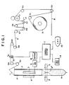
- a vertical type bag-making-and-filling packaging apparatus which comprises a tube-forming member 1, a bag-making cylindrical member 2 depending from the forming member 1, a pair of delivery belts 3 serving as delivery means, a vertical sealing device 4, a transverse sealing device 5 and a film roll A of wound packaging film or web a .
- the web a drawn out from the film roll A is properly introduced through guide rollers b1, b2, b3 & b11, to the tube-forming member 1.
- the web a is formed cylindrically when passing through the forming member 1, and then moves down in form of a tube a ⁇ along the outer periphery of the cylindrical member 2.
- the path of the web a moving from the film roll A to the position under the cylindrical member 2 will be hereinafter called a web-travelling path.
- the delivery belts 3 come into contact with the outer periphery of the tube a ⁇ and impart to the web a downward delivery force, which causes the web a to be drawn out against a tension lever 7 ⁇ and to move along the web-travelling path.
- the delivery belts 3 are disposed on the opposite sides of the outer periphery of the cylindrical member 2, and driving shafts of the delivery belts 3 are connected to a motor M through a clutch and brake 6 which starts and stops rotation of the shafts at proper times to perform intermittent rotation thereof and thereby to intermittently deliver the web a and the tube a ⁇ .
- the sealing device 5 may include a knife which is adapted to cut the sealed portion of the tube a ⁇ at the middle thereof transversely or along the width thereof so as to separate a bag a ⁇ from the lower end of the tube a ⁇ .
- an auxiliary delivery roller 7 for reducing the force required to draw out the web a from the film roll A
- a tension lever 7 ⁇ adapted for turning on and off the driving member of the delivery rollers 7 and serving as buffer or store for the web a
- another tension lever 8 for applying the brake at proper times to the web a drawn out from the film roll A.
- an encoder 10 serving as measuring means.
- the encoder 10 is connected through a control system C, incorporating a computer, to the driving member of the delivery belts 3, that is, the clutch and brake 6 so as to control start and stop of the delivery belts 3.
- the encoder 10 is disposed in opposition to the web a travelling along the web-travelling path, rotatable in the forward and reverse directions at the speed corresponding to the travelling speed of the web a .
- the encoder 10 transmits pulses corresponding to the run length of the web a moving on the encoder 10 to a central processing unit CPU (Fig. 2) of the control system C in order to measure the actual run length of the web a .
- the control system whose block diagram is shown in Fig. 2 comprises ROM 11 or memory in which fixed data such as a time lag value and control data such as programs are written, RAM 12 or memory for writing input data, such as, write count of pulses transmitted from the encoder 10, that is, plus pulses at forward rotation (advance of web) and minus pulses at reverse rotation (retraction of web), and a backup RAM 13 or memory for storing set data such as pulse number which determines delivery length of the web a , and the set data is inputted by means of a key pad 14 which is a data input unit.
- CRT 15 in the drawing is a display device.
- forward rotation of the encoder 10 causes the counting operation (counter) of RAM 12 to count the amount of rotation (pulse count) of the encoder 10, and when the count comes up to the set value of RAM 13, RAM 12 is reset to zero, the clutch is moved to off and the time lag sequence is started.
- a predetermined length of web travel is performed simply due to the inertia of the system with the clutch of the clutch and brake 6 off, after RAM 12 is reset to zero, and then the counter of RAM 12 starts counting of time lag and when the count comes up to the set time lag value stored in RAM 13, the brake of the clutch and brake 6 is turned on to stop the delivery belts 3, and the count in RAM 12 is returned to zero.
- the web a will be slackened due to inertia thereof downstream of the encoder 10, for example, at the guide roller b10, when the delivery belts 3 are stopped or the brake is turned on.
- the slackened length of the web a is measured by the encoder 10 and added to the count of RAM 12 in the following web delivery cycle, there remains no fear of error in web delivery.
- delivery belts are used as delivery means in this embodiment, other means such as delivery rollers may be employed, and measuring means may be freely selected from means other than the encoder.
- the time lag sequence may be omitted and the delivery belts may be designed to be stopped immediately when the encoder 10 measures the set length of the web.
- the bag-making cylindrical member 2 may be replaced by tubeless guide means.
- the measuring means measures the actual run length of the web and the delivery belts are stopped based upon the result, so that, even if there is any slippage between the delivery means and the web or tube or any error in mechanical precision, the delivering length of the web can be kept constant to improve the delivery precision of the packaging material.
- the load applied to the delivery means can be reduced, so that durability of the means is improved because of less wear or damage thereto and also damage to the packaging material is prevented.
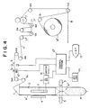
- Figs. 4 to 6 illustrate another embodiment of the present invention in which a registering system is combined to the apparatus shown in Figs. 1 to 3.
- the construction is almost the same as that shown in Fig. 1 except that there is a register mark sensor S provided on the web-travelling path, the film roll A ⁇ of wound web has equally spaced register marks thereon and there is a modified control system C ⁇ .
- register mark sensor S provided on the web-travelling path
- C ⁇ modified control system
- the register mark sensor S is disposed along with the encoder 10 on the web-travelling path, or more specifically on the path upstream of the tube-forming member 1.
- the encoder 10 and the sensor S are connected through the control system C ⁇ to the driving member of the delivery belts 3, that is, the clutch and brake 6 so as to control start and stop of the delivery belts 3.
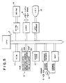
- the control system C ⁇ whose block diagram is shown in Fig. 5 comprises ROM 11 or memory for storing fixed data such as the decision value for deciding whether or not the register mark is valid and the time lag value and control data such as programs, and RAM 12 or memory which receives output signals from the encoder 10 and the register mark sensor S and has a counter function of counting pulse signals transmitted from the encoder 10.
- a backup RAM 13 is a memory for storing set values such as offset values to determine the run length of the web after a register mark is detected, and the set values are variably inputted by a key pad 14 which is a data input unit.
- the counter function of RAM 12 is executed by a reversible register mark decision counter 12a whose function is to prevent the same register mark from being sensed twice due to rewind of the web by back tension and whose count is added to the decision value of ROM 11 at forward rotation of the encoder 10 and is subtracted therefrom at its reverse rotation, a first offset counter 12b and a second offset counter 12b ⁇ which are incremented at forward rotation of the encoder 10 in the offset sequence after a register mark is detected, and a time lag counter 12c which is incremented at forward rotation of the encoder 10 in the time lag sequence after the count of the first or the second counter comes to the offset value.
- CRT 15 in Fig. 5 is a display device.
- Control operation of the system C ⁇ is shown in Fig. 6.
- Fixed data of 20 mm decision value and 7 mm time lag value is previously stored in ROM 11, and the set value such as the offset value is previously inputted digitally into the backup RAM 13 of the control system C ⁇ by means of the key pad 14, and then the packaging apparatus is started.
- the brake of the clutch and brake 6 is turned off and the clutch thereof on to actuate the delivery belts, and the delivery of the web is started, and accordingly the web a travels and the encoder 10 rotates to perform measurement.
- a forward rotation of the encoder 10 causes the register mark decision counter 12a of RAM 12 to subsequently decrement the decision count from 20 to 0.
- an offset sequence 1 in which the first offset counter 12b is operated and an offset sequence 2 in which the second offset counter 12b ⁇ is operated are programmed.
- the counters 12b and 12b ⁇ operate alternately. If the offset sequence 1 is started, the first offset counter 12b counts the amount of rotation (pulse count) of the encoder 10 in response to the travel of the web a . When the count reaches the offset value of RAM 13, the first offset counter of RAM 12 is reset to zero and the decision counter is reset to 20, and then the operation proceeds to the time lag sequence.
- time lag sequence a predetermined length of web travel is performed with the clutch of the clutch and brake 6 off, after the first offset counter of RAM 12 is reset to zero, and then the time lag counter 12c of RAM 12 starts counting, and when the count reaches the time lag value stored in ROM 11, the brake of the clutch and brake 6 is turned on to stop the delivery belts 3.
- the delivery belts 3 repeat start and stop to intermittently deliver the web a , the web a will be retracted or moves to and fro reciprocatingly on the sensor S due to slack of the web a , when the delivery belts 3 are stopped, and in such a case, the sensor S may detect the same register mark more than twice.
- the encoder is reversely rotated or repeats small amounts of forward and reverse rotations.
- the decision counter 12a of RAM 12 is incremented at forward rotation of the encoder 10 and decremented at reverse rotation thereof, and when the sensor S detects a register mark, it is decided whether or not the decision counter is zeroed.
- the detected register mark is decided to be the one previously detected, and transition to the offset sequence caused by detection of the register mark is inhibited to prevent malfunctions of the delivery belts 3.
- Such a process of preventing duplicate detection of a register mark by the decision counter is also effective to prevent malfunctions caused by, such as, misprint of register marks.
- stop time of the delivery means can be varied by inputting the set values (offset values) to the control system by the input unit so as to set or adjust stop timing of the web. Therefore, the registering operation of the packaging material is remarkably facilitated in comparison with the conventional sensor-moving system, and also has a good reproducibility. Furthermore, as the mesuring means measures the actual length of the web travel in the offset sequence, the set amount of the web delivery can be kept constant to improve delivery precision.
- attachment structure thereof is simple in comparison with that for a moving sensor, so that the structure associated with the sensor can be simplified.
Landscapes
- Engineering & Computer Science (AREA)
- Mechanical Engineering (AREA)
- Containers And Plastic Fillers For Packaging (AREA)
Claims (8)
- Machine d'emballage du type de mise en forme, de remplissage et de scellement, ladite machine d'emballage comprenant un moyen pour fournir une bande (a) à un élément de mise en forme d'un tube (2), un moyen de freinage (6) pour arrêter la bande après qu'une longueur prédéterminée a été fournie, des éléments de scellement longitudinaux (4) et transversaux (5) pour sceller ladite longueur prédéterminée pour former un sac scellé, un moyen de remplissage pour remplir le sac avant scellement, et un moyen de commande pour mesurer ladite longueur prédéterminée et pour faire fonctionner ledit moyen de freinage quand la longueur prédéterminée a été mesurée, caractérisée en ce que ledit moyen de commande (12) comprend un détecteur de mouvement (10) de bande, un moyen de comptage (12) qui est mis en fonctionnement par le détecteur (10) pour compter quand la bande avance, et un moyen de comparaison (13) qui fait fonctionner le moyen de freinage (6) quand le compte dans le compteur a une valeur préréglée, ledit compteur (12) et ledit détecteur (10) étant adaptés pour fonctionner dans la direction inverse dans laquelle ledit compteur (12) peut être mis en fonctionnement par le détecteur (10) pour décompter dans le cas où la bande fournit en trop au-delà du détecteur (10), due à l'inertie dans le système, et est ensuite rétractée de la quantité fournie en trop.
- Machine d'emballage suivant la revendication 1, caractérisée en ce que le moyen de commande comprend un embrayage dans ledit moyen pour entraîner la bande.
- Machine d'emballage suivant la revendication 2, caractérisée en ce que le détecteur comprend un codeur (10) placé près de la bande (a) et pouvant tourner dans les directions avant et arrière à une vitesse correspondant à la vitesse de la bande (a).
- Machine d'emballage suivant la revendication 3, caractérisée en ce que le codeur (10) transmet des impulsions correspondant à la longueur parcourue de la bande (a) se déplaçant au-dessus du codeur (10) vers une unité de traitement central du système de commande.
- Machine d'emballage suivant la revendication 4. caractérisée en ce que le moyen de comparaison comprend une mémoire morte ROM (11) pour emmagasiner des données fixes et des données de commande, et une mémoire vive de réserve RAM (13) dans laquelle peuvent être stockées les valeurs attendues prédéterminées pour le moyen de comptage (12).
- Machine d'emballage suivant la revendication 5, caractérisée en ce que la bande (a) est munie de marques d'enregistrement à intervalles réguliers le long de sa longueur et en ce que ledit détecteur est disposé pour détecter les marques.
- Machine d'emballage suivant la revendication 6, caractérisée en ce que le détecteur comprend un détecteur de marques d'enregistrement (S) placé en amont du codeur (10) et en ce que le moyen de comptage (12) comprend une pluralité de systèmes de comptage pour compter la longueur parcourue de la bande (a), la longueur décalée de la bande (a) qui est mesurée avant ladite longueur parcourue et une longueur de retard qui est mesurée après ladite longueur parcourue.
- Machine d'emballage suivant l'une des revendications précédentes, dans laquelle le compteur est une mémoire vive RAM (12).
Applications Claiming Priority (4)
| Application Number | Priority Date | Filing Date | Title |
|---|---|---|---|
| JP299523/85 | 1985-12-28 | ||
| JP29952485A JPS62158629A (ja) | 1985-12-28 | 1985-12-28 | 包装材繰出し装置の模様合せ機構 |
| JP299524/85 | 1985-12-28 | ||
| JP29952385A JPS62158630A (ja) | 1985-12-28 | 1985-12-28 | 製袋充填包装装置 |
Publications (3)
| Publication Number | Publication Date |
|---|---|
| EP0229216A2 EP0229216A2 (fr) | 1987-07-22 |
| EP0229216A3 EP0229216A3 (en) | 1988-01-20 |
| EP0229216B1 true EP0229216B1 (fr) | 1991-10-09 |
Family
ID=26561967
Family Applications (1)
| Application Number | Title | Priority Date | Filing Date |
|---|---|---|---|
| EP86108639A Expired - Lifetime EP0229216B1 (fr) | 1985-12-28 | 1986-06-25 | Machine d'emballage avec dispositif pour faire les sachets et les remplir |
Country Status (3)
| Country | Link |
|---|---|
| US (1) | US4754593A (fr) |
| EP (1) | EP0229216B1 (fr) |
| DE (1) | DE3681907D1 (fr) |
Families Citing this family (31)
| Publication number | Priority date | Publication date | Assignee | Title |
|---|---|---|---|---|
| US4860522A (en) * | 1988-06-20 | 1989-08-29 | Hayssen Manufacturing Company | Form, fill and seal registration system apparatus and method including variable length compensation and out of registration restoration |
| JPH0585521A (ja) * | 1991-07-30 | 1993-04-06 | Tokyo Autom Mach Works Ltd | 製袋充填包装装置 |
| US5746043A (en) * | 1992-06-29 | 1998-05-05 | Pacmac, Inc. | Convertible form, fill and seal packaging machine and method |
| US5505037A (en) * | 1992-06-29 | 1996-04-09 | Pacmac, Inc. | Vertical form, fill and seal machine for making recloseable bags |
| US5400565A (en) * | 1992-06-29 | 1995-03-28 | Pacmac, Inc. | Vertical form, fill and seal packaging machine for making recloseable product filled bags |
| US5768852A (en) * | 1992-06-29 | 1998-06-23 | Pacmac, Inc. | Vertical form, fill and seal machine, components and method for making reclosable bags |
| US6553744B1 (en) | 1992-06-29 | 2003-04-29 | Pacmac, Inc. | Packaging machine |
| US5930983A (en) * | 1992-06-29 | 1999-08-03 | Pacmac, Inc. | Form, fill and seal packaging machine with bag squeezer and method |
| EP0618138B1 (fr) * | 1993-04-01 | 1997-06-04 | Ferag AG | Dispositif de formation de paquets tubulaires portables de produits imprimés |
| DE19516868C2 (de) * | 1995-05-09 | 1998-07-02 | Rovema Gmbh | Schlauchbeutelmaschine |
| JP4096112B2 (ja) * | 1995-09-11 | 2008-06-04 | 四国化工機株式会社 | ウェッブの位置合せ装置 |
| DE19714245A1 (de) * | 1997-04-07 | 1998-10-08 | Focke & Co | Verfahren und Vorrichtung zum Herstellen (Füllen) von Beutelpackungen für Tabak |
| US5727366A (en) * | 1997-04-10 | 1998-03-17 | Milliken Research Corporation | Registration control |
| SE509534C2 (sv) | 1997-06-23 | 1999-02-08 | Sunds Defibrator Ind Ab | Mätanordning för kontinuerlig mätning av matad trådlängd |
| US6006501A (en) * | 1998-03-30 | 1999-12-28 | Winpak Lane, Inc. | Three-sided pouches, machine and method of making |
| EP1116659A1 (fr) * | 2000-01-17 | 2001-07-18 | Tetra Laval Holdings & Finance Sa | Machine d'emballage pour produire des emballages scellés contenant un produit alimentaire sous forme liquide |
| JP2001348010A (ja) * | 2000-06-06 | 2001-12-18 | Shikoku Kakoki Co Ltd | ウェッブ位置合せ装置およびこれを備えた包装機械 |
| DE10041523A1 (de) * | 2000-08-24 | 2002-03-07 | Rovema Gmbh | Vorrichtung zur Bildung einer Längsnaht eines Folienschlauches |
| NL1016524C2 (nl) * | 2000-11-01 | 2002-05-07 | Aquarius Bv | Vorm-, vul- en sluitmachine. |
| AU2002361125B2 (en) * | 2001-12-26 | 2006-11-09 | Tetra Laval Holdings & Finance S.A. | Filler |
| AU2003252695A1 (en) * | 2002-08-07 | 2004-02-25 | Ishida Co., Ltd. | Packing material roll, packing machine using the roll, and commercial goods processing system with the machine |
| SE0500074D0 (sv) * | 2005-01-10 | 2005-01-10 | Tetra Laval Holdings & Finance | Device and method for use in producing packages |
| DE102006052023A1 (de) * | 2006-11-03 | 2008-05-08 | Poly-Clip System Gmbh & Co. Kg | Abfüllvorrichtung und Verfahren zum Abfüllen von viskosem Füllgut |
| DE102011075431A1 (de) * | 2011-05-06 | 2012-11-08 | Robert Bosch Gmbh | Verfahren zum Optimieren der Förderung einer Packstoffbahn im Bereich einer Schlauchformeinrichtung einer Schlauchbeutelmaschine |
| EP2664554B1 (fr) | 2012-05-14 | 2015-08-26 | Ulma Packaging Technological Center, S. Coop | Machine et procédé d'emballage vertical |
| DE102013105551A1 (de) * | 2013-05-29 | 2014-12-04 | Windmöller & Hölscher Kg | Vorzugsvorrichtung für den Vorzug einer Folienbahn in einer Sackfüllanlage |
| ES2527643B1 (es) * | 2013-07-24 | 2015-11-04 | Ulma Packaging Technological Center, S.Coop. | Método y máquina para empaquetar productos |
| WO2015192250A1 (fr) * | 2014-06-19 | 2015-12-23 | Crawford Packaging Inc. | Dispositif de contrôle de machine d'emballage par rétraction de palettes |
| JP6510914B2 (ja) * | 2015-07-02 | 2019-05-08 | 株式会社タカゾノテクノロジー | 薬剤包装装置 |
| EP3141488B1 (fr) * | 2015-09-09 | 2020-04-22 | Tetra Laval Holdings & Finance S.A. | Machine d'emballage de production d'emballages à partir d'une feuille de matériau d'emballage |
| US11577870B1 (en) * | 2019-09-27 | 2023-02-14 | Amazon Technologies, Inc. | Isolated film tension and steering system |
Family Cites Families (11)
| Publication number | Priority date | Publication date | Assignee | Title |
|---|---|---|---|---|
| DE2164854A1 (de) * | 1971-12-28 | 1973-07-05 | Hoefliger & Karg | Vorrichtung zur steuerung einer materialbahn |
| US3889446A (en) * | 1974-06-18 | 1975-06-17 | Du Pont | Process for forming partitioned film packages and apparatus for use therein |
| IL47384A0 (en) * | 1974-06-21 | 1975-07-28 | Packaging Ind Inc | Web handling apparatus |
| US4023327A (en) * | 1976-06-04 | 1977-05-17 | Package Machinery Company | Control system for package making machine |
| US4128985A (en) * | 1977-10-31 | 1978-12-12 | Package Machinery Company | Control system for package making machine |
| US4288965A (en) * | 1979-08-27 | 1981-09-15 | Hayssen Manufacturing Company | Form-fill-seal packaging method and apparatus |
| US4391079A (en) * | 1980-08-21 | 1983-07-05 | Hayssen Manufacturing Company | Control system for cyclic machines |
| US4501109A (en) * | 1982-05-03 | 1985-02-26 | Rexham Corporation | Packaging machine with improved web feeding system |
| US4525977A (en) * | 1983-05-13 | 1985-07-02 | Doboy Packaging Machinery, Inc. | Wrapping machine and method |
| US4691499A (en) * | 1984-04-16 | 1987-09-08 | Fuji Machinery Company, Ltd. | Method of tensioning a web of packaging material |
| US4546596A (en) * | 1984-05-08 | 1985-10-15 | Hayssen Manufacturing Company | Method of and apparatus for forming, filling and sealing packages |
-
1986
- 1986-06-25 EP EP86108639A patent/EP0229216B1/fr not_active Expired - Lifetime
- 1986-06-25 DE DE8686108639T patent/DE3681907D1/de not_active Expired - Fee Related
-
1987
- 1987-08-05 US US07/081,549 patent/US4754593A/en not_active Expired - Lifetime
Also Published As
| Publication number | Publication date |
|---|---|
| EP0229216A3 (en) | 1988-01-20 |
| EP0229216A2 (fr) | 1987-07-22 |
| DE3681907D1 (de) | 1991-11-14 |
| US4754593A (en) | 1988-07-05 |
Similar Documents
| Publication | Publication Date | Title |
|---|---|---|
| EP0229216B1 (fr) | Machine d'emballage avec dispositif pour faire les sachets et les remplir | |
| CA1295037C (fr) | Appareil de faconnage, de remplissage et de scellement a systeme de reperes et a caracteristiques de compensation de longueur et d'interruption de sequence en cas de non-detectiond'un repere, et methode connexe | |
| US4909018A (en) | Control device and method for controlling the driving system of a packaging machine | |
| CA1306038C (fr) | Reperage bidirectionnel de bandes a indexation asservie | |
| USRE45846E1 (en) | Method adjusting tension applied to sheet, and device for the same | |
| KR100310966B1 (ko) | 쉬트장력조정방법및장치 | |
| US4067760A (en) | Gate control for printed web scanner | |
| US5695106A (en) | Correction of registered servo indexed webs | |
| US6603887B1 (en) | Process and apparatus for detecting printed marks | |
| US4296365A (en) | Method and apparatus for correcting errors of feeding of endless belt in automatic screen printing | |
| EP0251448A2 (fr) | Machine à imprimer sur une bande à format variable | |
| EP1044915B1 (fr) | Dispositif et méthode pour couper une bande | |
| JPH0427091B2 (fr) | ||
| JPH057255B2 (fr) | ||
| JPS63294314A (ja) | 製袋充填包装装置 | |
| JPH01197609A (ja) | 帯状部材のジョイント部のオーバーラップ量測定装置 | |
| JPH08584B2 (ja) | ロールラベルの切断位置制御装置 | |
| JP3676842B2 (ja) | 製袋充填包装機における原反フィルム送出し装置及び送出し方法並びに製袋充填包装機及び包装方法 | |
| JPH10119909A (ja) | 横型製袋充填機におけるフィルム移送装置 | |
| JP3676844B2 (ja) | 製袋充填包装機における原反フィルム送出し装置及び送出し方法並びに製袋充填包装機及び包装方法 | |
| JPH10119910A (ja) | 横型製袋充填機のフィルム移送装置 | |
| JPH0531459B2 (fr) | ||
| JPS63314405A (ja) | 包装袋用合成樹脂フィルムの印刷ピッチ測定装置 | |
| JPH0531458B2 (fr) | ||
| JP3656097B2 (ja) | カード搬送装置 |
Legal Events
| Date | Code | Title | Description |
|---|---|---|---|
| PUAI | Public reference made under article 153(3) epc to a published international application that has entered the european phase |
Free format text: ORIGINAL CODE: 0009012 |
|
| AK | Designated contracting states |
Kind code of ref document: A2 Designated state(s): DE FR GB |
|
| PUAL | Search report despatched |
Free format text: ORIGINAL CODE: 0009013 |
|
| AK | Designated contracting states |
Kind code of ref document: A3 Designated state(s): DE FR GB |
|
| 17P | Request for examination filed |
Effective date: 19880613 |
|
| 17Q | First examination report despatched |
Effective date: 19900213 |
|
| GRAA | (expected) grant |
Free format text: ORIGINAL CODE: 0009210 |
|
| AK | Designated contracting states |
Kind code of ref document: B1 Designated state(s): DE FR GB |
|
| REF | Corresponds to: |
Ref document number: 3681907 Country of ref document: DE Date of ref document: 19911114 |
|
| ET | Fr: translation filed | ||
| PLBE | No opposition filed within time limit |
Free format text: ORIGINAL CODE: 0009261 |
|
| STAA | Information on the status of an ep patent application or granted ep patent |
Free format text: STATUS: NO OPPOSITION FILED WITHIN TIME LIMIT |
|
| 26N | No opposition filed | ||
| REG | Reference to a national code |
Ref country code: GB Ref legal event code: IF02 |
|
| PGFP | Annual fee paid to national office [announced via postgrant information from national office to epo] |
Ref country code: FR Payment date: 20030610 Year of fee payment: 18 |
|
| PGFP | Annual fee paid to national office [announced via postgrant information from national office to epo] |
Ref country code: GB Payment date: 20030625 Year of fee payment: 18 |
|
| PGFP | Annual fee paid to national office [announced via postgrant information from national office to epo] |
Ref country code: DE Payment date: 20030707 Year of fee payment: 18 |
|
| PG25 | Lapsed in a contracting state [announced via postgrant information from national office to epo] |
Ref country code: GB Free format text: LAPSE BECAUSE OF NON-PAYMENT OF DUE FEES Effective date: 20040625 |
|
| PG25 | Lapsed in a contracting state [announced via postgrant information from national office to epo] |
Ref country code: DE Free format text: LAPSE BECAUSE OF NON-PAYMENT OF DUE FEES Effective date: 20050101 |
|
| GBPC | Gb: european patent ceased through non-payment of renewal fee |
Effective date: 20040625 |
|
| PG25 | Lapsed in a contracting state [announced via postgrant information from national office to epo] |
Ref country code: FR Free format text: LAPSE BECAUSE OF NON-PAYMENT OF DUE FEES Effective date: 20050228 |
|
| REG | Reference to a national code |
Ref country code: FR Ref legal event code: ST |