EP0227638B1 - Gasturbinenkleinkraftwerk - Google Patents
Gasturbinenkleinkraftwerk Download PDFInfo
- Publication number
- EP0227638B1 EP0227638B1 EP87100280A EP87100280A EP0227638B1 EP 0227638 B1 EP0227638 B1 EP 0227638B1 EP 87100280 A EP87100280 A EP 87100280A EP 87100280 A EP87100280 A EP 87100280A EP 0227638 B1 EP0227638 B1 EP 0227638B1
- Authority
- EP
- European Patent Office
- Prior art keywords
- turbine
- compressor
- volute
- engine
- gas turbine
- Prior art date
- Legal status (The legal status is an assumption and is not a legal conclusion. Google has not performed a legal analysis and makes no representation as to the accuracy of the status listed.)
- Expired
Links
- 238000002485 combustion reaction Methods 0.000 claims description 15
- 239000000446 fuel Substances 0.000 claims description 8
- 238000011144 upstream manufacturing Methods 0.000 claims description 7
- 230000003068 static effect Effects 0.000 claims 1
- 239000007789 gas Substances 0.000 description 22
- 238000004519 manufacturing process Methods 0.000 description 3
- 229910010293 ceramic material Inorganic materials 0.000 description 2
- 238000007567 mass-production technique Methods 0.000 description 2
- 241000928624 Coula edulis Species 0.000 description 1
- 229910052581 Si3N4 Inorganic materials 0.000 description 1
- 229910000831 Steel Inorganic materials 0.000 description 1
- 238000010521 absorption reaction Methods 0.000 description 1
- 229910045601 alloy Inorganic materials 0.000 description 1
- 239000000956 alloy Substances 0.000 description 1
- 239000000919 ceramic Substances 0.000 description 1
- 238000004891 communication Methods 0.000 description 1
- 230000002860 competitive effect Effects 0.000 description 1
- 238000010276 construction Methods 0.000 description 1
- 238000009826 distribution Methods 0.000 description 1
- 230000009977 dual effect Effects 0.000 description 1
- 238000010438 heat treatment Methods 0.000 description 1
- 239000007788 liquid Substances 0.000 description 1
- 238000012423 maintenance Methods 0.000 description 1
- 239000000463 material Substances 0.000 description 1
- 229910001092 metal group alloy Inorganic materials 0.000 description 1
- 238000005057 refrigeration Methods 0.000 description 1
- 230000001105 regulatory effect Effects 0.000 description 1
- 238000010079 rubber tapping Methods 0.000 description 1
- 230000003584 silencer Effects 0.000 description 1
- HQVNEWCFYHHQES-UHFFFAOYSA-N silicon nitride Chemical compound N12[Si]34N5[Si]62N3[Si]51N64 HQVNEWCFYHHQES-UHFFFAOYSA-N 0.000 description 1
- 239000007787 solid Substances 0.000 description 1
- 239000010959 steel Substances 0.000 description 1
Images


Classifications
-
- F—MECHANICAL ENGINEERING; LIGHTING; HEATING; WEAPONS; BLASTING
- F02—COMBUSTION ENGINES; HOT-GAS OR COMBUSTION-PRODUCT ENGINE PLANTS
- F02C—GAS-TURBINE PLANTS; AIR INTAKES FOR JET-PROPULSION PLANTS; CONTROLLING FUEL SUPPLY IN AIR-BREATHING JET-PROPULSION PLANTS
- F02C9/00—Controlling gas-turbine plants; Controlling fuel supply in air- breathing jet-propulsion plants
- F02C9/48—Control of fuel supply conjointly with another control of the plant
- F02C9/56—Control of fuel supply conjointly with another control of the plant with power transmission control
-
- F—MECHANICAL ENGINEERING; LIGHTING; HEATING; WEAPONS; BLASTING
- F01—MACHINES OR ENGINES IN GENERAL; ENGINE PLANTS IN GENERAL; STEAM ENGINES
- F01D—NON-POSITIVE DISPLACEMENT MACHINES OR ENGINES, e.g. STEAM TURBINES
- F01D25/00—Component parts, details, or accessories, not provided for in, or of interest apart from, other groups
- F01D25/24—Casings; Casing parts, e.g. diaphragms, casing fastenings
-
- F—MECHANICAL ENGINEERING; LIGHTING; HEATING; WEAPONS; BLASTING
- F01—MACHINES OR ENGINES IN GENERAL; ENGINE PLANTS IN GENERAL; STEAM ENGINES
- F01D—NON-POSITIVE DISPLACEMENT MACHINES OR ENGINES, e.g. STEAM TURBINES
- F01D9/00—Stators
- F01D9/02—Nozzles; Nozzle boxes; Stator blades; Guide conduits, e.g. individual nozzles
- F01D9/026—Scrolls for radial machines or engines
-
- F—MECHANICAL ENGINEERING; LIGHTING; HEATING; WEAPONS; BLASTING
- F01—MACHINES OR ENGINES IN GENERAL; ENGINE PLANTS IN GENERAL; STEAM ENGINES
- F01D—NON-POSITIVE DISPLACEMENT MACHINES OR ENGINES, e.g. STEAM TURBINES
- F01D9/00—Stators
- F01D9/02—Nozzles; Nozzle boxes; Stator blades; Guide conduits, e.g. individual nozzles
- F01D9/04—Nozzles; Nozzle boxes; Stator blades; Guide conduits, e.g. individual nozzles forming ring or sector
-
- F—MECHANICAL ENGINEERING; LIGHTING; HEATING; WEAPONS; BLASTING
- F02—COMBUSTION ENGINES; HOT-GAS OR COMBUSTION-PRODUCT ENGINE PLANTS
- F02C—GAS-TURBINE PLANTS; AIR INTAKES FOR JET-PROPULSION PLANTS; CONTROLLING FUEL SUPPLY IN AIR-BREATHING JET-PROPULSION PLANTS
- F02C3/00—Gas-turbine plants characterised by the use of combustion products as the working fluid
- F02C3/04—Gas-turbine plants characterised by the use of combustion products as the working fluid having a turbine driving a compressor
- F02C3/10—Gas-turbine plants characterised by the use of combustion products as the working fluid having a turbine driving a compressor with another turbine driving an output shaft but not driving the compressor
- F02C3/103—Gas-turbine plants characterised by the use of combustion products as the working fluid having a turbine driving a compressor with another turbine driving an output shaft but not driving the compressor the compressor being of the centrifugal type
-
- F—MECHANICAL ENGINEERING; LIGHTING; HEATING; WEAPONS; BLASTING
- F02—COMBUSTION ENGINES; HOT-GAS OR COMBUSTION-PRODUCT ENGINE PLANTS
- F02C—GAS-TURBINE PLANTS; AIR INTAKES FOR JET-PROPULSION PLANTS; CONTROLLING FUEL SUPPLY IN AIR-BREATHING JET-PROPULSION PLANTS
- F02C6/00—Plural gas-turbine plants; Combinations of gas-turbine plants with other apparatus; Adaptations of gas- turbine plants for special use
- F02C6/18—Plural gas-turbine plants; Combinations of gas-turbine plants with other apparatus; Adaptations of gas- turbine plants for special use using the waste heat of gas-turbine plants outside the plants themselves, e.g. gas-turbine power heat plants
-
- Y—GENERAL TAGGING OF NEW TECHNOLOGICAL DEVELOPMENTS; GENERAL TAGGING OF CROSS-SECTIONAL TECHNOLOGIES SPANNING OVER SEVERAL SECTIONS OF THE IPC; TECHNICAL SUBJECTS COVERED BY FORMER USPC CROSS-REFERENCE ART COLLECTIONS [XRACs] AND DIGESTS
- Y02—TECHNOLOGIES OR APPLICATIONS FOR MITIGATION OR ADAPTATION AGAINST CLIMATE CHANGE
- Y02E—REDUCTION OF GREENHOUSE GAS [GHG] EMISSIONS, RELATED TO ENERGY GENERATION, TRANSMISSION OR DISTRIBUTION
- Y02E20/00—Combustion technologies with mitigation potential
- Y02E20/14—Combined heat and power generation [CHP]
Definitions
- This invention relates to a gas turbine power plant and is particularly though not exclusively concerned with a relatively small power plant driven by a gas turbine engine, producing electrical energy and energy for heating, refrigeration and air condi- tionning. Such a power plant would be useful for domestic purpose, small businesses and factories.
- GB-A-866 869 and US-A-2 946 192 there are described such small gas turbine engine power plants. They each comprise a gas turbine engine made up of a plurality of components which partially define the surfaces of the gas flow through the engine. Those components includes a compressor and a compressor driving turbine mounted in housing which comprises a central core and upstream and downstream end plates. A combustion arrangement is also provided.
- a compressor exhaust volute is defined by a surface on the upstream end plate and a surface on the core
- a turbine inlet volute is defined by another surface on the core and a surface on the down- steam end plate, the central core including an inlet duct extending from the compressor exhaust volute to combustion arrangement inlet and an outlet duct extending from the combustion arrangement outlet to the compressor driving turbine inlet volute.
- the central core includes all of the ducts in communication with the combustion arrangement, thereby making it easy to manufacture by mass production techniques from such materials as ceramic.
- a gas turbine engine 10 comprises a centrifugal compressor 12 driven by a centripetal turbine 14 via a shaft 16 to which the compressor and turbine are both attached.
- the shaft 16 is journalled in a gas bearing 18 and the rotor assembly of shaft, compressor and turbine also has a gas thrust bearing 20.
- the rotor assembly is mounted in a housing 22 which comprises upstream and downstream end plates 24,26 respectively and a split central core 28 clamped between the end plates by suitable securing means, e.g. nut and bolt arrangements 30.
- the upstream end plate 24 has an intake flare 32 attached to it and the inside surface of the end plate is shaped to provide the housing of the compressor 12 and partially defines the compressor outlet 34 and exhaust volute 36.
- the central core has a surface which in conjunction with the corresponding surfaces of the end plate defines the compressor outlet and exhaust volute.
- a duct 38 is formed in the central core and connects the exhaust volute 36 with a side mounted combustion chamber 39 ( Figure 2).
- end plate 26 and the downstream face of the central core are shaped to define a turbine inlet volute 40 which is connected to the outlet from the combustion chamber by a duct 42 in the central core.
- the outlets of the ducts 38 and 42 are concentric and are attached to the combustion chamber by a suitable flanged connector 39a.
- the combustion chamber 39 which is screwed to the connector 39a, has outer and inner casings 39b and 39c respectively.
- the inner casing has an upstream air swirler 39d, and a fuel injector 39e is mounted on the outer casing and extends through the centre of the air swirler.
- the fuel injector as for gas fuel, but a liquid fuel or a dual fuel injector can be provided.
- An igniter 39f is also mounted on the outer casing, and extends through the wall of the inner casing.
- the inner and outer casings define an annular space 39g which receives compressed air from the duct 38. The products of combustion are discharged from the inner casing to the duct 42.
- a ring of nozzle guide vanes 44 Downstream of the volute 40 and between the central core and the end plate 26 is mounted a ring of nozzle guide vanes 44 to direct the hot, high velocity gases from the combustion chamber into the turbine 14.
- the securing means 30 also attach a power turbine module 46 to the rotor assembly.
- the module 46 comprises two casings 48,50 which locate and retain in position the components of the module, and which are secured together by suitable clamping means (not shown). Inside the casing 48, there is located a diffuser housing 52, the internal surface of which defines the outer surface of an annular diffuser 54.
- the housing 52 is formed from two components, a diffuser block 56 and a ring 58 to which is attached a row of inlet guide vanes 60.
- the other surface defining the diffuser duct 54 is defined by the external surface of the bullet 62 of a power turbine rotor 64 on which are mounted turbine blades 66.
- the power turbine rotor 64 is mounted in a gas journal bearing 68 and has a gas thrust bearing 70. Both of these bearings are located in a bearing support structure 72 contained within and held in position by the casing 50.
- the exhaust gases from the power turbine pass into an exhaust duct 74 which terminates in a volute (not shown) to conduct the exhaust to atmosphere through a suitable opening (not shown) in the casing 50.
- the exhaust duct 74 is defined partly by the ring 58 and partly by surfaces formed on the bearing support structure 72.
- the compressor, compressor driving turbine, power turbine and associated guide vaned can be made from a ceramic material, e.g. silicon nitride, or from a good quality alloy depending on the nature of the fuel used.
- Other components which can be made from a ceramic material are the split casing 28, the end plate 26 and the power turbine stator ring and turbine casing 58.
- the remaining components, particularly the containment casing 48 can be formed from steel , or a suitable metal alloy.
- gas turbine is made from a very small number of components which can be easily assembled either by hand or by machine.
- a particular feature of the design is the multifunction capability of some of the components.
- the bullet 62 of the power turbine also partially defines the annular diffuser duct 54, and since it will rotate at high speed will induct a whirl velocity into the gases from the turbine 14.
- This feature can be used to aerodynamic advantage in the design of the power turbine and the inlet guide vanes 60.
- the casing 48 as well as locating and retaining the diffuser duct components also acts as a containment for the power turbine in the case of turbine overspeed.
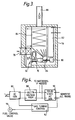
- the gas turbine engine 10 is shown located in a silenced cabinet 76 having an intake filter and silencer 78.
- the power turbine 64 drives a variable frequency wide voltage regulated a.c. generator 80, the output from which passes to a control and distribution system 82, shown in more detail in Figure 4.
- the exhaust from the gas turbine passes into a boiler and/or absorption system 84, and exhausts to atmosphere through a stack 86 which can be silenced.
- the output from the a.c. generator 80 passes to a rectifier and voltage regulator 88 and hence to the domestic mains via a solid state a.c. generator 90.
- a tapping can be taken to charge batteries if required.
- a gas turbine control 92 is powered from the mains supply and receives signals inter alia from the a.c. generator to control the fuel supply to the engine by a valve 94.
Claims (1)
- Gasturbinentriebwerk mit einem durch eine Turbine über eine Welle angetriebenen Kompressor, mit einer Verbrennungseinrichtung, die vom Kompressor eine Druckluftströmung und eine Brennstoffströmung empfängt und die Verbrennungsprodukte nach der Turbine ausströmen läßt und mit einer Nutzleistungsturbine, die von den Abgasen der den Kompressor antreibenden Turbine angetrieben wird und eine Last antreibt, wobei das Triebwerk mehrere Bauteile aufweist, die teilweise die Oberflächen der Gasströmung durch das Triebwerk definieren und eine der Oberflächen auf einem statischen Bauteil und die andere einem rotierenden Bauteil ausgebildet ist und wobei der Kompressor und die Kompressorantriebsturbine drehbar in einem Gehäuse gelagert sind, das einen zentralen Kern und stromaufwärtige Endplatten aufweist, dadurch gekennzeichnet, daß eine Kompressor-Auslaßschnecke (36) durch eine Oberfläche an der stromaufwärtigen Endplatte (24) und eine Oberfläche am Kern (28) definiert ist und daß eine Turbinen-Einlaßschnecke (40) durch eine weitere Oberfläche des Kerns (28) und eine Oberfläche auf der stromabwärtigen Endplatte (26) definiert ist, wobei der zentrale Kern (28) einen von der Kompressor-Auslaßschnecke (36) nach dem Einlaß der Verbrennungseinrichtung (39) verlaufenden Einlaßkanal (38) und einen Auslaßkanal (42) aufweist, der sich von dem Auslaß der Verbrennungseinrichtung (39) nach der Einlaßschnecke (40) der Kompressorantriebsturbine erstreckt.
Applications Claiming Priority (2)
| Application Number | Priority Date | Filing Date | Title |
|---|---|---|---|
| GB8400356 | 1984-01-07 | ||
| GB8400356 | 1984-01-07 |
Related Parent Applications (1)
| Application Number | Title | Priority Date | Filing Date |
|---|---|---|---|
| EP84308462.5 Division | 1984-12-05 |
Publications (2)
| Publication Number | Publication Date |
|---|---|
| EP0227638A1 EP0227638A1 (de) | 1987-07-01 |
| EP0227638B1 true EP0227638B1 (de) | 1990-11-07 |
Family
ID=10554670
Family Applications (3)
| Application Number | Title | Priority Date | Filing Date |
|---|---|---|---|
| EP87100280A Expired EP0227638B1 (de) | 1984-01-07 | 1984-12-05 | Gasturbinenkleinkraftwerk |
| EP84308462A Expired EP0148590B1 (de) | 1984-01-07 | 1984-12-05 | Gasturbinenkraftwerke |
| EP87100279A Withdrawn EP0225868A1 (de) | 1984-01-07 | 1984-12-05 | Gasturbinenkleinkraftwerk |
Family Applications After (2)
| Application Number | Title | Priority Date | Filing Date |
|---|---|---|---|
| EP84308462A Expired EP0148590B1 (de) | 1984-01-07 | 1984-12-05 | Gasturbinenkraftwerke |
| EP87100279A Withdrawn EP0225868A1 (de) | 1984-01-07 | 1984-12-05 | Gasturbinenkleinkraftwerk |
Country Status (7)
| Country | Link |
|---|---|
| US (1) | US4598542A (de) |
| EP (3) | EP0227638B1 (de) |
| JP (1) | JPS60156936A (de) |
| CA (1) | CA1251050A (de) |
| DE (1) | DE3483583D1 (de) |
| GB (1) | GB2153437A (de) |
| NO (1) | NO160807C (de) |
Families Citing this family (25)
| Publication number | Priority date | Publication date | Assignee | Title |
|---|---|---|---|---|
| US4951460A (en) * | 1989-01-11 | 1990-08-28 | Stewart & Stevenson Services, Inc. | Apparatus and method for optimizing the air inlet temperature of gas turbines |
| GB9016353D0 (en) * | 1990-07-25 | 1990-09-12 | Csir | Power pack |
| GB2330648A (en) * | 1997-10-24 | 1999-04-28 | Robert Pickering | Domestic boiler heated by gas turbine |
| WO1999032762A1 (en) * | 1997-12-19 | 1999-07-01 | Alliedsignal Inc. | An uninterruptible microturbine power generating system |
| EP1040260B1 (de) | 1997-12-20 | 2003-07-23 | AlliedSignal Inc. | Regelungsvorrichtung für mikroturbine mit konstanter turbineneinlasstemperatur |
| EP1059421B1 (de) * | 1999-06-09 | 2005-08-17 | AlliedSignal Inc. | Mikroturbinenkraftanlage |
| SE521955C2 (sv) * | 2000-05-30 | 2003-12-23 | Turbec Ab | Integrerad gaskompressor |
| US6622489B1 (en) | 2000-10-25 | 2003-09-23 | Hybrid Power Generation Systems, Llc | Integrated gas booster modulation control method |
| US6513318B1 (en) | 2000-11-29 | 2003-02-04 | Hybrid Power Generation Systems Llc | Low emissions gas turbine engine with inlet air heating |
| US6571563B2 (en) | 2000-12-19 | 2003-06-03 | Honeywell Power Systems, Inc. | Gas turbine engine with offset shroud |
| US6536217B2 (en) | 2000-12-20 | 2003-03-25 | Honeywell Power Systems Inc. | Liquid fuel reverse purge |
| GB2373299B (en) * | 2001-03-12 | 2004-10-27 | Alstom Power Nv | Re-fired gas turbine engine |
| EP1561270A2 (de) * | 2002-11-15 | 2005-08-10 | Sprint Communications Company, L.P. | Protonenaustauschermembran-basiertes stromspeisungssystem für eine telekommunikationsanlage |
| US6960838B2 (en) | 2002-11-15 | 2005-11-01 | Sprint Communications Company L.P. | Power system for a telecommunication facility |
| US7456513B2 (en) * | 2002-11-15 | 2008-11-25 | Sprint Communications Company L.P. | Modular cell site with air-turbine backup |
| US6930402B1 (en) * | 2003-05-15 | 2005-08-16 | Sprint Communications Company L.P. | Power system for a telecommunication facility |
| JP4638878B2 (ja) * | 2003-11-04 | 2011-02-23 | マン ウント フンメル ゲゼルシャフト ミット ベシュレンクテル ハフツング | スパイラル通路がハウジング中間部材に設けられた流体機械 |
| US7081687B2 (en) * | 2004-07-22 | 2006-07-25 | Sprint Communications Company L.P. | Power system for a telecommunications facility |
| US7615889B2 (en) * | 2005-05-02 | 2009-11-10 | Sprint Communications Company L.P. | Modular cell site |
| US9142844B2 (en) | 2005-05-18 | 2015-09-22 | Sprint Communications Company L.P. | Power system for a telecommunications network |
| US20060263656A1 (en) * | 2005-05-18 | 2006-11-23 | Sprint Communications Company L.P. | Power system with reformer |
| US7370666B2 (en) * | 2005-09-14 | 2008-05-13 | Sprint Communications Company L.P. | Power system with computer-controlled fuel system |
| US7557531B2 (en) * | 2005-12-19 | 2009-07-07 | Sprint Communications Company L.P. | Power system utilizing flow batteries |
| CN102434217A (zh) * | 2011-11-01 | 2012-05-02 | 哈尔滨东安发动机(集团)有限公司 | 一体式悬臂转子结构 |
| US9587507B2 (en) | 2013-02-23 | 2017-03-07 | Rolls-Royce North American Technologies, Inc. | Blade clearance control for gas turbine engine |
Family Cites Families (27)
| Publication number | Priority date | Publication date | Assignee | Title |
|---|---|---|---|---|
| FR1002293A (fr) * | 1946-09-03 | 1952-03-04 | Rateau Soc | Installation à turbine à gaz pour production combinée de chaleur et d'énergie et réglage de cette installation |
| US2709893A (en) * | 1949-08-06 | 1955-06-07 | Laval Steam Turbine Co | Gas turbine power plant with heat exchanger and cooling means |
| US2709889A (en) * | 1951-06-22 | 1955-06-07 | Wadsworth W Mount | Gas turbine using revolving ram jet burners |
| GB723368A (en) * | 1952-06-23 | 1955-02-09 | Rover Co Ltd | Vehicle gas turbines |
| GB756413A (en) * | 1954-10-08 | 1956-09-05 | David Dutton Budworth | Improvements in or relating to the supply and the combustion of fuel in gas turbines |
| US2923526A (en) * | 1955-03-31 | 1960-02-02 | Gen Electric | Turbine |
| US2944785A (en) * | 1955-05-18 | 1960-07-12 | Thompson Ramo Wooldridge Inc | Impeller for turbine engine and the like |
| US2821067A (en) * | 1956-05-28 | 1958-01-28 | Boeing Co | Combustion chamber construction in a gas turbine engine |
| CH359929A (de) * | 1957-10-01 | 1962-01-31 | Bbc Brown Boveri & Cie | Gasturbine für Schiffsantrieb |
| US2946192A (en) * | 1958-05-16 | 1960-07-26 | Standard Motor Co Ltd | Gas turbine power plant |
| US3187188A (en) * | 1959-07-21 | 1965-06-01 | Curtiss Wright Corp | High speed turbo-generator |
| GB866969A (en) * | 1959-12-14 | 1961-05-03 | George Colville Best | Gas turbine engines |
| FR1254037A (fr) * | 1960-02-29 | 1961-02-17 | Sulzer Ag | Turbine radiale pour milieux compressibles |
| DE1426265A1 (de) * | 1962-03-12 | 1968-12-19 | Volvo Ab | Gasturbinenanlage |
| GB1027530A (en) * | 1964-03-02 | 1966-04-27 | Vlastimir Davidovic | Gas turbine cycle improvement |
| US3422800A (en) * | 1967-06-19 | 1969-01-21 | Gen Electric | Combined gas turbine and waste heat boiler control system |
| GB1315307A (en) * | 1969-08-21 | 1973-05-02 | Cav Ltd | Turbo superchargers for internal combustion engines |
| US3751886A (en) * | 1971-08-31 | 1973-08-14 | Westinghouse Electric Corp | Vertical steam drum |
| DE2165528A1 (de) * | 1971-12-30 | 1973-07-12 | Kloeckner Humboldt Deutz Ag | Einrichtung zum herstellen eines geringen spaltes zwischen den umlaufenden schaufeln und der wandung einer stroemungsmaschine |
| FR2197420A5 (de) * | 1972-08-25 | 1974-03-22 | Cav Ltd | |
| FR2264972B1 (de) * | 1974-03-20 | 1977-06-17 | Turbine Ind | |
| US4076452A (en) * | 1974-04-09 | 1978-02-28 | Brown, Boveri-Sulzer Turbomaschinen Ag | Gas turbine plant |
| US4009568A (en) * | 1975-10-30 | 1977-03-01 | General Motors Corporation | Turbine support structure |
| SE402147B (sv) * | 1975-12-05 | 1978-06-19 | United Turbine Ab & Co | Gasturbinanleggning med tre i samma gaspassage anordnade koaxiella turbinrotorer |
| DE2706110C3 (de) * | 1977-02-14 | 1981-07-09 | Aktiengesellschaft Kühnle, Kopp & Kausch, 6710 Frankenthal | Verdichtergehäuse vorzugsweise für Abgasturbolader |
| DE2941252A1 (de) * | 1979-10-11 | 1981-05-07 | Joachim Dr. 7031 Aidlingen Artmann | Verfahren zur dezentralen erzeugung von elektro- und waermeenergie |
| SE423741B (sv) * | 1980-09-29 | 1982-05-24 | Motor Turbine & Transmissions | Gasturbinmaskineri, speciellt for fordonsdrift |
-
1984
- 1984-12-05 EP EP87100280A patent/EP0227638B1/de not_active Expired
- 1984-12-05 EP EP84308462A patent/EP0148590B1/de not_active Expired
- 1984-12-05 GB GB08430676A patent/GB2153437A/en not_active Withdrawn
- 1984-12-05 EP EP87100279A patent/EP0225868A1/de not_active Withdrawn
- 1984-12-05 DE DE8787100280T patent/DE3483583D1/de not_active Expired - Fee Related
- 1984-12-13 US US06/681,258 patent/US4598542A/en not_active Expired - Fee Related
- 1984-12-27 JP JP59281882A patent/JPS60156936A/ja active Granted
-
1985
- 1985-01-04 CA CA000471504A patent/CA1251050A/en not_active Expired
- 1985-01-04 NO NO850046A patent/NO160807C/no unknown
Also Published As
| Publication number | Publication date |
|---|---|
| US4598542A (en) | 1986-07-08 |
| NO160807B (no) | 1989-02-20 |
| EP0225868A1 (de) | 1987-06-16 |
| DE3483583D1 (de) | 1990-12-13 |
| EP0148590B1 (de) | 1989-04-12 |
| JPS60156936A (ja) | 1985-08-17 |
| GB8430676D0 (en) | 1985-01-16 |
| EP0227638A1 (de) | 1987-07-01 |
| GB2153437A (en) | 1985-08-21 |
| JPH0580571B2 (de) | 1993-11-09 |
| NO160807C (no) | 1989-05-31 |
| EP0148590A2 (de) | 1985-07-17 |
| EP0148590A3 (en) | 1985-11-21 |
| NO850046L (no) | 1985-07-08 |
| CA1251050A (en) | 1989-03-14 |
Similar Documents
| Publication | Publication Date | Title |
|---|---|---|
| EP0227638B1 (de) | Gasturbinenkleinkraftwerk | |
| EP2110531B1 (de) | Abgasturbolader | |
| US4002023A (en) | Stationary power-generating plant | |
| US5960625A (en) | Constant volume combustion turbine with plurality flow turbine wheels | |
| EP0210249B1 (de) | Gasgenerator mit radialturbine und doppeltem lufteinlauf | |
| PL180015B1 (pl) | Sposób i urzadzenie do wytwarzania energii, zwlaszcza elektrycznej PL PL PL PL PL | |
| US2625794A (en) | Gas turbine power plant with diverse combustion and diluent air paths | |
| GB1113087A (en) | Gas turbine power plant | |
| CN101153546A (zh) | 双轴燃气涡轮 | |
| ES410317A1 (es) | Perfeccionamiento en motores de turbina de gas. | |
| US5160080A (en) | Gas turbine engine and method of operation for providing increased output shaft horsepower | |
| GB2189845A (en) | Gas turbine cooling air transferring apparatus | |
| US4064690A (en) | Gas turbine power plant | |
| WO1999023374A3 (en) | Jet engine having radial turbine blades and flow-directing turbine manifolds | |
| GB1229007A (de) | ||
| US7062900B1 (en) | Single wheel radial flow gas turbine | |
| MXPA05006926A (es) | Motor universal de turbina de gas de flujo radial multicombustible. | |
| GB2063366A (en) | Turbocharger and adaptions thereof | |
| EP0811752A1 (de) | Gasturbine mit von innen nach aussen durchströmtem radialrad | |
| US2962206A (en) | Centrifugal compressor for a gas turbine engine | |
| RU2623592C1 (ru) | Роторный газотурбинный двигатель | |
| CA1223746A (en) | Gas turbine engine with pulverized coal firing | |
| GB884646A (en) | Improvements relating to gas turbine power plants | |
| GB1009115A (en) | Improvements in and relating to gas turbine plants | |
| US2692081A (en) | Supercharger arrangement for thermal power plants |
Legal Events
| Date | Code | Title | Description |
|---|---|---|---|
| PUAI | Public reference made under article 153(3) epc to a published international application that has entered the european phase |
Free format text: ORIGINAL CODE: 0009012 |
|
| AC | Divisional application: reference to earlier application |
Ref document number: 148590 Country of ref document: EP |
|
| AK | Designated contracting states |
Kind code of ref document: A1 Designated state(s): CH DE FR GB IT LI SE |
|
| 17P | Request for examination filed |
Effective date: 19870715 |
|
| 17Q | First examination report despatched |
Effective date: 19891020 |
|
| GRAA | (expected) grant |
Free format text: ORIGINAL CODE: 0009210 |
|
| ITF | It: translation for a ep patent filed |
Owner name: BARZANO' E ZANARDO MILANO S.P.A. |
|
| AC | Divisional application: reference to earlier application |
Ref document number: 148590 Country of ref document: EP |
|
| AK | Designated contracting states |
Kind code of ref document: B1 Designated state(s): CH DE FR GB IT LI SE |
|
| PGFP | Annual fee paid to national office [announced via postgrant information from national office to epo] |
Ref country code: SE Payment date: 19901121 Year of fee payment: 7 |
|
| PGFP | Annual fee paid to national office [announced via postgrant information from national office to epo] |
Ref country code: CH Payment date: 19901122 Year of fee payment: 7 |
|
| REF | Corresponds to: |
Ref document number: 3483583 Country of ref document: DE Date of ref document: 19901213 |
|
| ITTA | It: last paid annual fee | ||
| ET | Fr: translation filed | ||
| PLBE | No opposition filed within time limit |
Free format text: ORIGINAL CODE: 0009261 |
|
| STAA | Information on the status of an ep patent application or granted ep patent |
Free format text: STATUS: NO OPPOSITION FILED WITHIN TIME LIMIT |
|
| 26N | No opposition filed | ||
| PG25 | Lapsed in a contracting state [announced via postgrant information from national office to epo] |
Ref country code: SE Effective date: 19911206 |
|
| PG25 | Lapsed in a contracting state [announced via postgrant information from national office to epo] |
Ref country code: LI Effective date: 19911231 Ref country code: CH Effective date: 19911231 |
|
| REG | Reference to a national code |
Ref country code: CH Ref legal event code: PL |
|
| PGFP | Annual fee paid to national office [announced via postgrant information from national office to epo] |
Ref country code: FR Payment date: 19941108 Year of fee payment: 11 |
|
| PGFP | Annual fee paid to national office [announced via postgrant information from national office to epo] |
Ref country code: GB Payment date: 19941116 Year of fee payment: 11 |
|
| PGFP | Annual fee paid to national office [announced via postgrant information from national office to epo] |
Ref country code: DE Payment date: 19941122 Year of fee payment: 11 |
|
| EUG | Se: european patent has lapsed |
Ref document number: 87100280.4 Effective date: 19920704 |
|
| PG25 | Lapsed in a contracting state [announced via postgrant information from national office to epo] |
Ref country code: GB Effective date: 19951205 |
|
| GBPC | Gb: european patent ceased through non-payment of renewal fee |
Effective date: 19951205 |
|
| PG25 | Lapsed in a contracting state [announced via postgrant information from national office to epo] |
Ref country code: FR Effective date: 19960830 |
|
| PG25 | Lapsed in a contracting state [announced via postgrant information from national office to epo] |
Ref country code: DE Effective date: 19960903 |
|
| REG | Reference to a national code |
Ref country code: FR Ref legal event code: ST |