EP0226977B1 - Strahlungsbildaufzeichnungs- und Wiedergabevorrichtung - Google Patents
Strahlungsbildaufzeichnungs- und Wiedergabevorrichtung Download PDFInfo
- Publication number
- EP0226977B1 EP0226977B1 EP86117326A EP86117326A EP0226977B1 EP 0226977 B1 EP0226977 B1 EP 0226977B1 EP 86117326 A EP86117326 A EP 86117326A EP 86117326 A EP86117326 A EP 86117326A EP 0226977 B1 EP0226977 B1 EP 0226977B1
- Authority
- EP
- European Patent Office
- Prior art keywords
- sheet
- image recording
- stimulable phosphor
- tray
- image
- Prior art date
- Legal status (The legal status is an assumption and is not a legal conclusion. Google has not performed a legal analysis and makes no representation as to the accuracy of the status listed.)
- Expired
Links
Images


Classifications
-
- G—PHYSICS
- G01—MEASURING; TESTING
- G01T—MEASUREMENT OF NUCLEAR OR X-RADIATION
- G01T1/00—Measuring X-radiation, gamma radiation, corpuscular radiation, or cosmic radiation
- G01T1/16—Measuring radiation intensity
- G01T1/20—Measuring radiation intensity with scintillation detectors
- G01T1/2012—Measuring radiation intensity with scintillation detectors using stimulable phosphors, e.g. stimulable phosphor sheets
Definitions
- This invention relates to a radiation image recording and read-out apparatus for exposing stimulable phosphor sheets to a radiation passing through an object to have a radiation image of the object stored thereon, exposing the respective stimulable phosphor sheets to stimulating rays which cause them to emit light in proportion to the stored radiation energy, and detecting and converting the emitted light into electric signals.
- This invention particularly relates to a radiation image recording and read-out apparatus wherein the stimulable phosphor sheets are circulated by a circulation and conveyance means along a predetermined circulation path and reused for radiation image recording.
- phosphors When certain kinds of phosphors are exposed to a radiation such as X-rays, a-rays, p-rays, y-rays, cathode rays or ultraviolet rays, they store a part of the energy of the radiation. Then, when the phosphor which has been exposed to the radiation is exposed to stimulating rays such as visible light, light is emitted by the phosphor in proportion to the stored energy of the radiation. A phosphor exhibiting such properties is referred to as a stimulable phosphor.
- a stimulable phosphor sheet As disclosed in U.S. Patent No. 4,258,264, 4,276,473, 4,315,318 and 4,387,428, and Japanese Unexamined Patent Publication No. 56(1981)-11395, it has been proposed to use a stimulable phosphor in a radiation image recording and reproducing system. Specifically, a sheet comprising the stimulable phosphor (hereinafter referred to as a stimulable phosphor sheet or simply as a sheet) is first exposed to a radiation passing through an object to have a radiation image stored thereon, and is then scanned with stimulating rays which cause it to emit light in proportion to the radiation energy stored.
- a stimulable phosphor sheet As disclosed in U.S. Patent No. 4,258,264, 4,276,473, 4,315,318 and 4,387,428, and Japanese Unexamined Patent Publication No. 56(1981)-11395, it has been proposed to use a stimulable phosphor in a radiation image recording and reproducing system. Specifically,
- the light emitted by the stimulable phosphor sheet when the sheet is exposed to the stimulating rays is photoelectrically detected and converted into an electric image signal, which is processed as desired to reproduce a visible image having an improved image quality, particularly a high diagnostic efficiency and accuracy.
- the finally obtained visible image may be reproduced in the form of a hard copy or may be displayed on a cathode ray tube (CRT).
- the stimulable phosphor sheet is used to temporarily store the radiation image in order to reproduce the final visible image therefrom on a final recording medium. For economical reasons, therefore, it is desirable that the stimulable phosphor sheet be used repeatedly.
- a mobile X-ray diagnostic station such as a traveling X-ray diagnostic station in the form of a vehicle like a bus which is provided with a radiation image recording and read-out apparatus for use in the aforesaid radiation image recording and reproducing system and moves from place to place to record radiation images for mass medical examinations
- the radiation energy remaining on the stimulable phosphor sheet after it is scanned with stimulating rays to read out the radiation image stored thereon should be erased by using a method as described, for example, in U.S. Patent No. 4,400,619 or Japanese Unexamined Patent Publication No. 56(1981)-12599.
- the stimulable phosphor sheet may then be used again for radiation image recording.
- the built-in type radiation image recording and read-out apparatus is one that can be very conveniently used for, for example, mounting on a mobile X-ray diagnostic station as mentioned above, it is desirable that the apparatus can conduct continuous image recording and read-out operations at as short intervals as possible and is small.
- stimulable phosphor sheets are circulated through the image recording, image read-out and erasing steps.
- image recording is conducted continuously as mentioned above, it is necessary that a plurality of stimulable phosphor sheets readied for image recording by erasing be fed continuously to the image recording section.
- the time required for the image read-out step and the time required for the erasing step are longer than the time required for the image recording step, among which the time required for the image read-out step is the longest (for example, approximately 45 seconds).
- the stimulable phosphor sheets subjected to image recording must be sequentially sent to the image read-out section for conducting image read-out therefrom, the image read-out time is very much longer than the image recording time, and the second and subsequent sheets on which image recording is finished cannot immediately be conveyed to the image read-out section. Therefore, it is also necessary to provide the circulation path between the image recording section and the image read-out section with a waiting zone for keeping waiting a plurality of stimulable phosphor sheets carrying a radiation image stored thereon, from which the sheets may be taken out one by one each time the image read-out section is readied for the read-out operation.
- the waiting zone is proposed in, for example, Japanese Patent Application Nos.
- the primary object of the present invention is to provide a built-in type radiation image recording and read-out apparatus provided with a configuration which makes continuous image recording possible without increasing the apparatus size and making the mechanism complicated.
- Another object of the present invention is to provide a built-in type radiation image recording and read-out apparatus which efficiently conducts continuous image recording.
- the present invention provides a radiation image recording and read-out apparatus as defined in claim 1 comprising:
- the circulation and conveyance means it is possible to conduct ordinary circulation and conveyance of the stimulable phosphor sheet by the circulation and conveyance means by positioning an arbitrary one of the trays, which are housed in the casing at the image recording section, on the circulation path. Also, it is possible to utilize some of the trays in the casing as a waiting zone for keeping waiting the erased stimulable phosphor sheets, and to take the stimulable phosphor sheet out of an arbitrary tray housing the erased stimulable phosphor sheet and send said stimulable phosphor sheet to the image recording position for conducting the image recording.
- the stimulable phosphor sheets having different sizes are housed in the tray unit, it becomes possible to selectively use the stimulable phosphor sheet of an arbitrary size suitable for the size of the object subjected to image recording. Further, it is possible to conduct image read-out for the stimulable phosphor sheet in an arbitrary priority order.
- FIG. I an embodiment of the radiation image recording and read-out apparatus in accordance with the present invention is provided with a circulation path I.
- a stimulable phosphor sheet (hereinafter simply referred to as the sheet) 2 is conveyed and circulated along the circulation path I by a circulation and conveyance means 10 comprising endless belts, rollers, guide plates or the like.
- An image recording section 100 for recording a radiation image on the sheet 2, an image read-out section 20 for reading out the radiation image stored on the sheet 2, and an erasing section 30 for erasing radiation energy remaining on the sheet 2 after the image read-out are sequentially disposed on the circulation path I in the conveyance direction of the sheet 2.
- a plurality of the sheets 2, 2, ... are conveyed and circulated sequentially through the image recording section 100, the image read-out section 20 and the erasing section 30 by the circulation and conveyance means 10.
- the sheet 2 is exposed to a radiation emitted by a radiation source 101 and passing through an object 3 to have a radiation image of the object 3 stored on the sheet 2.
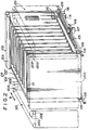
- the image recording section 100 is provided with a tray unit 103 moveable in the direction as indicated by the arrow B and comprising a casing 104 and a plurality of trays 102, 102, ... each housing a single sheet 2, which are housed in the casing 104.
- a conveyance mechanism as will be described later and conveyed to the image recording position shown.
- the sheet 2 is conveyed by the conveyance mechanism into an empty tray 102.
- the tray unit 103 is moved in the direction as indicated by the arrow B so that the tray 102 holding said sheet 2 is positioned above unloading rollers IIA and llB provided at the lower end of the image recording section 100.
- the lower end of the tray 102 positioned above the unloading rollers IIA and llB is then opened to allow the sheet 2 to fall under its weight and transfer the sheet 2 to the unloading rollers IIA and IIB.
- the sheet 2 is then conveyed by the circulation and conveyance means in the directions as indicated by the arrows Al, A2 and A3 to the image read-out section 20.
- the number of the sheets 2, 2, ... which can be conveyed and circulated through the image recording section 100, the image read-out section 20 and the erasing section 30 in the apparatus is equal to the number of the trays 102, 102, ... at the image recording section 100.
- the sheet 2 carrying a radiation image stored thereon is scanned with stimulating rays 21 such as a laser beam which cause the sheet 2 to emit light in proportion to the stored radiation energy, and the emitted light is photoelectrically detected by a photoelectric read-out means 22 constituted by a photomultiplier or the like to obtain an electric image signal for use in reproduction of a visible image.
- Reference numeral 23 denotes a stimulating ray source
- reference numeral 24 denotes a light deflector such as a galvanometer mirror.
- Reference numeral 26 designates a reflection mirror for reflecting the light emitted by the sheet 2 towards a light guide member 22a of the photoelectric read-out means 22.
- the light guide member 22a guides the light through total reflection therein up to a photodetector 22b constituted by a photomultiplier or the like.
- the sheet 2 sent to the image read-out section 20 is conveyed by the circulation and conveyance means 10 in the direction as indicated by the arrow A4, and the whole surface of the sheet 2 is scanned two-dimensionally by the stimulating rays 21 deflected approximately normal to the conveyance direction.
- the light emitted by the sheet 2 during the scanning is detected by the photodetector 22b via the light guide member 22a.
- Image read-out is conducted in this manner.
- the electric image signal thus obtained is sent to an image processing circuit (not shown) and subjected therein to the necessary image processing.
- the electric image signal thus processed is then sent to an image reproducing apparatus (not shown).
- the image reproducing apparatus may be a display device such as a cathode ray tube (CRT), or may be a photographic reproducing apparatus for reproducing a visible image on a photographic film by point-by-point scanning, or may be a memory device using e.g. a magnetic tape for memorizing the electric image signal for later use in image reproduction.
- the optical members disposed at the image read-out section 20 are not limited to those described above.
- a long photomultiplier may be disposed as the photoelectric read-out means along the main scanning line, and the light emitted by the sheet 2 may be detected without using the light guide member 22a.
- the sheet 2 is conveyed by the circulation and conveyance means 10 in the directions as indicated by the arrows A5 and A6 to the erasing section 30.
- the erasing section 30 is provided with a plurality of erasing light sources 31, 31, ... constituted by fluorescent lamps, tungsten-filament lamps, sodium lamps, xenon lamps, iodine lamps or the like and the sheet 2 is exposed to the erasing light emitted by the erasing light sources 31, 31, . .. for releasing the residual radiation energy from the sheet 2 while the sheet 2 is conveyed in the direction as indicated by the arrow A7.
- the sheet 2 is conveyed by the circulation and conveyance means 10 in the directions as indicated by the arrows A8, A9 and AIO to the image recording section 100.
- the tray unit 103 at the image recording section 100 is moved in the direction as indicated by the arrow B so that the empty tray 102 for receiving the sheet 2 is positioned below a pair of feed rollers 12A and 12B disposed at the upper end of the image recording section 100.
- the sheet 2 conveyed into the tray 102 is then taken out of the tray 102 when required for use in image recording.
- this embodiment is provided with the image recording section 100 at which a plurality of the sheets 2, 2, ... are housed in the form held in the trays 102, 102, ..., it is possible to conduct continuous image recording efficiently without causing the apparatus size to become large.
- the configuration and operations of the image recording section 100 will now be described with reference to Figures 2 to 6.
- each of the trays 102, 102, ... comprises a supporting plate 102A, and a rotatable bottom plate 102B approximately normal to the supporting plate 102A.
- the upper face, the lower face, the right side face and the left side face of the casing 104 are opened with only the framework remaining for allowing feeding and unloading of the sheet 2 from the casing 104.
- a rack 105 provided at the lower end of one side face of the casing 104 is engaged with a pinion 106, the pinion 106 is rotated by a motor 107, and wheels 109, 109, ... secured to the lower end of casing 104 are moved along rails 108, 108.
- the position of the tray unit 103 shown in Figure I is the left end position of the movement of the tray unit 103.
- the tray unit 103 is moveable up to the position as indicated by the chain line in Figure I.
- the rack 105, the pinion 106, the motor 107, the rails 108, 108, and the wheels 109, 109, ... constitute the movement means for the casing 104.
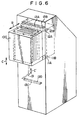
- a conveyance mechanism 120 is provided on the lateral side of the tray unit 103.
- the conveyance mechanism 120 takes the sheet 2 out of one side end of the tray 102 disposed at a first predetermined position adjacent to rollers 120A and 120B, conveys the sheet 2 to the image recording position, and then conveys it from the image recording position into the tray 102 via the other side end thereof disposed at a second predetermined position adjacent to rollers 120H and 1201.
- the first predetermined position at which the sheet 2 is taken out of the tray 102 may be different from the second predetermined position at which the sheet 2 is inserted into the tray 102, they are made to coincide with each other in this embodiment.
- the aforesaid movement means moves the tray unit 103 so that an arbitrary tray 102 in the tray unit 103 may be associated with the feed rollers 12A and 12B, and the unloading rollers IIA and IIB, and disposed at the aforesaid predetermined position.
- the width of each tray 102 is slightly smaller than the width of the sheet 2.
- the tray unit 103 Before continuous image recording is started in this embodiment, as many sheets 2, 2, ... as possible readied for image recording are maintained in the tray unit 103, for example, by finishing image read-out and erasing for all the sheets 2, 2, ... used in the apparatus.
- the tray unit 103 is moved by the aforesaid movement means so that the tray 102 housing a sheet 2 which is to be used comes to the predetermined position.
- a cutaway portion 102a is formed in the bottom plate 102B of each tray 102 at said other side end thereof, and a sheet pushing-out plate 110 is provided in the vicinity of the cutaway portion 102a of the tray 102 disposed at the predetermined position at the image recording section 100.
- the sheet pushing-out plate 110 is maintained at a position retracted downwardly from the tray 102 as indicated by the solid line in Figure 4.
- the sheet pushing-out plate 110 is rotated by a movement means (not shown) constituted by a motor or the like through the cutaway portion 102a of the tray 102 up to a position PI, and pushes one side edge of the tray 102 to have the other side edge of the tray 102 gripped between the rollers 120A and 120B of the conveyance mechanism 120.
- the tray 102 gripped between the rollers 120A and 120B is conveyed in the direction as indicated by the arrow in Figure 3, and positioned on a supporting plate 120C provided on the front side.
- the sheet 2 is subjected to image recording.
- the leading end and the rear end of the sheet 2 as viewed in the conveyance direction are nipped between rollers 120D and 120E, and between rollers 120F and 120G.
- a shielding plate III formed of lead or the like is provided between the tray unit 103 and the supporting plate 120C so that the other sheets 2, 2, ... housed in the tray unit 103 are not adversely affected by a radiation emitted to the sheet 2 at the image recording position for image recording.
- the sheet 2 is conveyed by the conveyance mechanism 120 in the direction as indicated by the arrow, and conveyed by the rollers 120H and 1201 into the empty tray 102 in the tray unit 103.
- the empty tray 102 may be the same tray 102 from which the sheet 2 subjected to the image recording was taken out, or may be a different empty tray.
- the sheet 2 used first for the image recording may be conveyed into said different tray 102 which is now empty.
- the position of the tray unit 103 is adjusted so that a desired empty tray 102 is disposed at the predetermined position before the sheet 2 on which the image recording is finished is returned to the tray unit 103.
- the rollers 120H and 1201 convey the sheet 2 carrying a radiation image stored thereon up to a position midway of the tray 102.
- a pair of feed rollers 121A and 121B are provided above the sheet pushing-out plate 110.
- the feed rollers 121A and 121B receive the sheet 2 conveyed by the rollers 120H and 1201, and insert the sheet 2 close to the predetermined housing position in the tray 102.
- the sheet pushing-out plate 110 is rotated to a position P2, pushes the rear edge of the sheet 2 as viewed in the conveyance direction, and separates the sheet 2 from the feed rollers 121A and 121B.
- the tray unit 103 by the movement means to dispose the tray 102 housing the sheet 2 readied for image recording and the empty tray 102 for housing the sheet 2, on which image recording is finished, alternately at the predetermined position, thereby conducting continuous image recording efficiently with a compact mechanism.
- the erased sheets 2, 2, ... are collected in the trays 102, 102, ... before the image recording is started, it is possible to send the erased sheets 2, 2, ... sequentially from the trays 102, 102, ... to the image recording zone, and to conduct the image recording continuously on a plurality of the sheets 2, 2, ... without providing a stack zone between the image recording section 100 and the erasing section 30.
- the sheets 2, 2, ... on which the image recording is finished may be returned sequentially into the trays 102, 102, ... and made to wait therein, it is possible to send the sheet 2 carrying a radiation image stored thereon at an arbitrary timing from the tray 102 to the image read-out section 20, and to omit a stack zone between the image read-out section 20 and the image recording section 100. Conveyance of the sheet 2 subjected to the image recording to the image read-out section 20 is conducted each time image read-out from the previously sent sheet 2 is finished at the image read-out section 20.
- the tray unit 103 Before the conveyance, the tray unit 103 is moved by the movement means, and the tray 102 housing the sheet 2 which is to be conveyed to the image read-out section 20 is positioned above the unloading rollers IIA and IIB provided at the lower end of the image recording section 100.
- a lever 132 provided with a protrusion 132a and rotated by a drive means 131 constituted by a rotary solenoid or the like in the direction as indicated by the arrow D is disposed on the lateral side of the tray 102 at the unloading position.
- the protrusion 132a is engaged with a protrusion 102b defining the cutaway portion 102a of the bottom plate 102B of the tray 102, and rotates the bottom plate 102B in the direction as indicated by the arrow D' as the lever 132 is rotated in the direction as indicated by the arrow D.
- the bottom plate 102B is thus moved to a plane as indicated by the broken line in Figure 5 approximately flush with the supporting plate 102A of the tray 102.
- the unloading rollers IIA and IIB grip the leading end of the falling sheet 2, and convey the sheet 2 out of the image recording section 100.
- the lever 132 is returned to the position shown in Figure 5, and the bottom plate 102B is returned to the position indicated by the solid line.
- the sheet 2 unloaded from the image recording section 100 is subjected to the image read-out at the image read-out section 20 and the erasing at the erasing section 30, and then returned to the image recording section 100.
- a control means for controlling the sheet conveyance timing of the two systems memorizing whether the respective trays 102, 102, ... in the tray unit 103 house sheets 2, 2, ... which are erased or carrying a radiation image stored thereon, or are empty, and moving a desired tray 102 to the necessary position.
- this embodiment is provided with a control section 40 above the image read-out section 20.
- the image recording section 100 is moveable in the direction as indicated by the arrow C between the position indicated by the solid line in Figure I and the position indicated by the chain line so that the image recording position may be changed vertically.
- a pair of conveying rollers 13A and 13B and a pair of conveying rollers 13C and 13D constituting a part of the circulation and conveyance means 10 are moved by being supported on a supporting shaft 13 in a manner interlocked with the movement of the image recording section 100.
- the supporting shaft 13 is disposed so that it does not intersect the movement space of the image recording section 100, and is moved in the direction as indicated by the arrow C ' .
- the supporting shaft 13 is moved by adjusting the roller spacings so that the spaces from the conveying rollers 13A and 13B to the adjacent conveying rollers 14A and 14B and to the feed rollers 12A and 12B are respectively smaller than the length of the sheet 2, and the spaces from the conveying rollers 13C and 13D to the adjacent conveying rollers 15A and 15B and to the unloading rollers IIA and IIB are respectively smaller than the length of the sheet 2, wherever the image recording section 100 is positioned within its movement range.
- the supporting shaft 13 and the conveying rollers 13A, 13B, 13C and 13D are disposed at the positions indicated by the chain line.
- the trays in the tray unit may also be disposed in an inclined form or horizontally.
- sheet feeding and unloading from the trays may be conducted by using a conveyance mechanism and a movement means adapted to the tray holding means.
- the configurations of the movement means for the tray unit and the conveyance mechanism at the image recording section are not limited to those in the aforesaid embodiment.
- a single common means may be disposed on one side of the tray unit.
Landscapes
- Physics & Mathematics (AREA)
- Health & Medical Sciences (AREA)
- Life Sciences & Earth Sciences (AREA)
- General Physics & Mathematics (AREA)
- High Energy & Nuclear Physics (AREA)
- Molecular Biology (AREA)
- Spectroscopy & Molecular Physics (AREA)
- Radiography Using Non-Light Waves (AREA)
- Apparatus For Radiation Diagnosis (AREA)
- Measurement Of Radiation (AREA)
Claims (7)

Applications Claiming Priority (2)
| Application Number | Priority Date | Filing Date | Title |
|---|---|---|---|
| JP60279839A JPH0644130B2 (ja) | 1985-12-12 | 1985-12-12 | 放射線画像情報記録読取装置 |
| JP279839/85 | 1985-12-12 |
Publications (2)
| Publication Number | Publication Date |
|---|---|
| EP0226977A1 EP0226977A1 (de) | 1987-07-01 |
| EP0226977B1 true EP0226977B1 (de) | 1990-06-13 |
Family
ID=17616644
Family Applications (1)
| Application Number | Title | Priority Date | Filing Date |
|---|---|---|---|
| EP86117326A Expired EP0226977B1 (de) | 1985-12-12 | 1986-12-12 | Strahlungsbildaufzeichnungs- und Wiedergabevorrichtung |
Country Status (4)
| Country | Link |
|---|---|
| US (1) | US4739166A (de) |
| EP (1) | EP0226977B1 (de) |
| JP (1) | JPH0644130B2 (de) |
| DE (1) | DE3671980D1 (de) |
Families Citing this family (6)
| Publication number | Priority date | Publication date | Assignee | Title |
|---|---|---|---|---|
| US4814619A (en) * | 1987-03-20 | 1989-03-21 | Fuji Photo Film Co., Ltd. | Stacker for stimulable phosphor sheets |
| US4939366A (en) * | 1987-06-25 | 1990-07-03 | Fuji Photo Film Co., Ltd. | Radiation image recording and read-out apparatus, and radiation image recording, read-out and reproducing apparatus |
| US5278410A (en) * | 1991-11-27 | 1994-01-11 | Eastman Kodak Company | X-ray cassette positioner and cogbelt for use therewith |
| US5366213A (en) * | 1993-11-29 | 1994-11-22 | Eastman Kodak Company | Method for handling documents at a high volume scanner |
| US20110065574A1 (en) * | 2009-09-15 | 2011-03-17 | Kabushiki Kaisha Toshiba | Image decoloring apparatus, image decoloring method, and sheet transfer apparatus |
| JP2014126826A (ja) * | 2012-12-27 | 2014-07-07 | Fujifilm Corp | 放射線画像読取装置、プログラム及び放射線画像読取方法 |
Family Cites Families (11)
| Publication number | Priority date | Publication date | Assignee | Title |
|---|---|---|---|---|
| SE312069B (de) * | 1964-10-09 | 1969-06-30 | A Gidlund | |
| JPS5512429A (en) * | 1978-07-12 | 1980-01-29 | Fuji Photo Film Co Ltd | Radioactive image reader |
| GB2029594A (en) * | 1978-09-02 | 1980-03-19 | Glover E | A film projection system |
| US4315318A (en) * | 1978-12-26 | 1982-02-09 | Fuji Photo Film Co., Ltd. | Method and apparatus for processing a radiation image |
| JPS55116340A (en) * | 1979-02-28 | 1980-09-06 | Fuji Photo Film Co Ltd | Method and device for processing gradation of radiation picture |
| JPS5611392A (en) * | 1979-07-11 | 1981-02-04 | Fuji Photo Film Co Ltd | Method and device for converting radiation image |
| JPS56104645A (en) * | 1979-12-25 | 1981-08-20 | Fuji Photo Film Co Ltd | Radiation picture treating method and its device |
| CA1192674A (en) * | 1981-10-16 | 1985-08-27 | Hisatoyo Kato | Radiation image recording and read-out system |
| JPS5868739A (ja) * | 1981-10-21 | 1983-04-23 | Fuji Photo Film Co Ltd | 蓄積性螢光体シ−トのノイズ消去装置 |
| JPS5872044A (ja) * | 1981-10-27 | 1983-04-28 | Fuji Photo Film Co Ltd | 優先処理機能を備えた放射線画像情報記録再生システム |
| US4687932A (en) * | 1984-06-01 | 1987-08-18 | Fuji Photo Film Co., Ltd. | Radiation image recording and read-out apparatus |
-
1985
- 1985-12-12 JP JP60279839A patent/JPH0644130B2/ja not_active Expired - Lifetime
-
1986
- 1986-12-12 EP EP86117326A patent/EP0226977B1/de not_active Expired
- 1986-12-12 US US06/941,119 patent/US4739166A/en not_active Expired - Lifetime
- 1986-12-12 DE DE8686117326T patent/DE3671980D1/de not_active Expired - Fee Related
Also Published As
| Publication number | Publication date |
|---|---|
| US4739166A (en) | 1988-04-19 |
| JPH0644130B2 (ja) | 1994-06-08 |
| EP0226977A1 (de) | 1987-07-01 |
| DE3671980D1 (de) | 1990-07-19 |
| JPS62138842A (ja) | 1987-06-22 |
Similar Documents
| Publication | Publication Date | Title |
|---|---|---|
| US4771174A (en) | Radiation image recording and read-out apparatus | |
| US4810874A (en) | Radiation image read-out apparatus and cassette used for the same | |
| US4900926A (en) | Radiation image read-out apparatus | |
| US4777365A (en) | Radiation image read-out apparatus | |
| EP0231926B1 (de) | Vorrichtung zum Auslesen eines Strahlenbildes | |
| US4931641A (en) | Radiation image read-out apparatus | |
| EP0226977B1 (de) | Strahlungsbildaufzeichnungs- und Wiedergabevorrichtung | |
| US4861995A (en) | Radiation image read-out apparatus | |
| US4687932A (en) | Radiation image recording and read-out apparatus | |
| EP0179418B1 (de) | Strahlungsbildwiedergabevorrichtung | |
| US4906847A (en) | Radiation image read-out and reproducing apparatus | |
| EP0307937B1 (de) | Vorrichtung zum Auslesen von Strahlungsbildern | |
| EP0219836B1 (de) | Gerät zur Wiedergabe eines Strahlungsbildes | |
| US4855599A (en) | Radiation image read-out apparatus | |
| US5061852A (en) | Radiation image read-out apparatus | |
| US4760255A (en) | Radiation image recording and read-out apparatus | |
| US4806758A (en) | Radiation image read-out apparatus | |
| US4814619A (en) | Stacker for stimulable phosphor sheets | |
| EP0169344B1 (de) | Strahlungsbildaufzeichnungs- und -wiedergabevorrichtung | |
| US4897546A (en) | Radiation image recording, read-out and reproducing apparatus | |
| JPH01237642A (ja) | 放射線画像情報記録読取装置 | |
| CA1257713A (en) | Radiation image read-out apparatus | |
| JPS6317442A (ja) | 放射線画像情報読取装置 | |
| JPS62175380A (ja) | 蓄積性蛍光体シ−ト用スタツカ | |
| JPS63259542A (ja) | 放射線画像情報読取装置 |
Legal Events
| Date | Code | Title | Description |
|---|---|---|---|
| PUAI | Public reference made under article 153(3) epc to a published international application that has entered the european phase |
Free format text: ORIGINAL CODE: 0009012 |
|
| AK | Designated contracting states |
Kind code of ref document: A1 Designated state(s): DE FR NL |
|
| 17P | Request for examination filed |
Effective date: 19871229 |
|
| 17Q | First examination report despatched |
Effective date: 19890803 |
|
| GRAA | (expected) grant |
Free format text: ORIGINAL CODE: 0009210 |
|
| AK | Designated contracting states |
Kind code of ref document: B1 Designated state(s): DE FR NL |
|
| REF | Corresponds to: |
Ref document number: 3671980 Country of ref document: DE Date of ref document: 19900719 |
|
| ET | Fr: translation filed | ||
| PLBE | No opposition filed within time limit |
Free format text: ORIGINAL CODE: 0009261 |
|
| STAA | Information on the status of an ep patent application or granted ep patent |
Free format text: STATUS: NO OPPOSITION FILED WITHIN TIME LIMIT |
|
| 26N | No opposition filed | ||
| PGFP | Annual fee paid to national office [announced via postgrant information from national office to epo] |
Ref country code: FR Payment date: 20021210 Year of fee payment: 17 |
|
| PGFP | Annual fee paid to national office [announced via postgrant information from national office to epo] |
Ref country code: NL Payment date: 20021219 Year of fee payment: 17 |
|
| PGFP | Annual fee paid to national office [announced via postgrant information from national office to epo] |
Ref country code: DE Payment date: 20030130 Year of fee payment: 17 |
|
| PG25 | Lapsed in a contracting state [announced via postgrant information from national office to epo] |
Ref country code: NL Free format text: LAPSE BECAUSE OF NON-PAYMENT OF DUE FEES Effective date: 20040701 Ref country code: DE Free format text: LAPSE BECAUSE OF NON-PAYMENT OF DUE FEES Effective date: 20040701 |
|
| PG25 | Lapsed in a contracting state [announced via postgrant information from national office to epo] |
Ref country code: FR Free format text: LAPSE BECAUSE OF NON-PAYMENT OF DUE FEES Effective date: 20040831 |
|
| NLV4 | Nl: lapsed or anulled due to non-payment of the annual fee |
Effective date: 20040701 |
|
| REG | Reference to a national code |
Ref country code: FR Ref legal event code: ST |