EP0226497B1 - Current collector for a trolley bus - Google Patents
Current collector for a trolley bus Download PDFInfo
- Publication number
- EP0226497B1 EP0226497B1 EP86402553A EP86402553A EP0226497B1 EP 0226497 B1 EP0226497 B1 EP 0226497B1 EP 86402553 A EP86402553 A EP 86402553A EP 86402553 A EP86402553 A EP 86402553A EP 0226497 B1 EP0226497 B1 EP 0226497B1
- Authority
- EP
- European Patent Office
- Prior art keywords
- cradle
- main body
- head according
- trolley bus
- bus head
- Prior art date
- Legal status (The legal status is an assumption and is not a legal conclusion. Google has not performed a legal analysis and makes no representation as to the accuracy of the status listed.)
- Expired - Lifetime
Links
- 230000010355 oscillation Effects 0.000 claims description 10
- 238000003825 pressing Methods 0.000 claims description 3
- 230000035939 shock Effects 0.000 claims description 2
- 238000006073 displacement reaction Methods 0.000 claims 1
- 230000005540 biological transmission Effects 0.000 description 8
- 238000000465 moulding Methods 0.000 description 7
- 238000000034 method Methods 0.000 description 5
- 238000009987 spinning Methods 0.000 description 5
- 229910003460 diamond Inorganic materials 0.000 description 4
- 239000010432 diamond Substances 0.000 description 4
- 238000003754 machining Methods 0.000 description 4
- 238000012423 maintenance Methods 0.000 description 4
- 238000004519 manufacturing process Methods 0.000 description 4
- 208000031968 Cadaver Diseases 0.000 description 3
- OKTJSMMVPCPJKN-UHFFFAOYSA-N Carbon Chemical compound [C] OKTJSMMVPCPJKN-UHFFFAOYSA-N 0.000 description 3
- 229910052799 carbon Inorganic materials 0.000 description 3
- 238000000605 extraction Methods 0.000 description 3
- 238000010438 heat treatment Methods 0.000 description 3
- 239000000463 material Substances 0.000 description 3
- 230000006835 compression Effects 0.000 description 2
- 238000007906 compression Methods 0.000 description 2
- 239000000470 constituent Substances 0.000 description 2
- 238000005520 cutting process Methods 0.000 description 2
- 238000013461 design Methods 0.000 description 2
- 210000005069 ears Anatomy 0.000 description 2
- 238000005304 joining Methods 0.000 description 2
- 238000012986 modification Methods 0.000 description 2
- 230000004048 modification Effects 0.000 description 2
- 241000269800 Percidae Species 0.000 description 1
- 241000826860 Trapezium Species 0.000 description 1
- 238000004026 adhesive bonding Methods 0.000 description 1
- XAGFODPZIPBFFR-UHFFFAOYSA-N aluminium Chemical compound [Al] XAGFODPZIPBFFR-UHFFFAOYSA-N 0.000 description 1
- 229910052782 aluminium Inorganic materials 0.000 description 1
- 238000005266 casting Methods 0.000 description 1
- 238000007796 conventional method Methods 0.000 description 1
- 238000001816 cooling Methods 0.000 description 1
- 238000012937 correction Methods 0.000 description 1
- 230000006378 damage Effects 0.000 description 1
- 238000009826 distribution Methods 0.000 description 1
- 230000005489 elastic deformation Effects 0.000 description 1
- 230000003203 everyday effect Effects 0.000 description 1
- 230000002349 favourable effect Effects 0.000 description 1
- 238000009434 installation Methods 0.000 description 1
- 210000000056 organ Anatomy 0.000 description 1
- BASFCYQUMIYNBI-UHFFFAOYSA-N platinum Chemical compound [Pt] BASFCYQUMIYNBI-UHFFFAOYSA-N 0.000 description 1
- 230000000284 resting effect Effects 0.000 description 1
- 229910001220 stainless steel Inorganic materials 0.000 description 1
- 239000010935 stainless steel Substances 0.000 description 1
Images


Classifications
-
- B—PERFORMING OPERATIONS; TRANSPORTING
- B60—VEHICLES IN GENERAL
- B60L—PROPULSION OF ELECTRICALLY-PROPELLED VEHICLES; SUPPLYING ELECTRIC POWER FOR AUXILIARY EQUIPMENT OF ELECTRICALLY-PROPELLED VEHICLES; ELECTRODYNAMIC BRAKE SYSTEMS FOR VEHICLES IN GENERAL; MAGNETIC SUSPENSION OR LEVITATION FOR VEHICLES; MONITORING OPERATING VARIABLES OF ELECTRICALLY-PROPELLED VEHICLES; ELECTRIC SAFETY DEVICES FOR ELECTRICALLY-PROPELLED VEHICLES
- B60L5/00—Current collectors for power supply lines of electrically-propelled vehicles
- B60L5/04—Current collectors for power supply lines of electrically-propelled vehicles using rollers or sliding shoes in contact with trolley wire
- B60L5/08—Structure of the sliding shoes or their carrying means
- B60L5/085—Structure of the sliding shoes or their carrying means with carbon contact members
Definitions
- the present invention relates to the field of trolleybuses on similar vehicles, and more particularly a trolleybus head of the type comprising a cradle body mounted pivoting at the end of the pole, a cradle mounted on the cradle body with a link allowing an oscillation around a substantially vertical axis and a tilting around a substantially horizontal axis, said cradle receiving a wear shoe for the transmission of current to a cable carried by the pole, via a shunt connected to the cradle.
- the cradle has in its upper part a part having a groove with inclined sides, often called a friction shoe.
- a wear shoe is housed by conical wedging in the groove of this part, and a safety strip is provided to prevent any accidental extraction in reverse, the conical wedging being naturally provided in such a way that the tightening tends to be reinforced when the trolley bus is in forward gear.
- the wiper is a wearing part which must be changed very regularly, and often every day. Therefore, recessed mounting, if it is mechanically safe, involves a tedious disassembly operation: the operator must first unscrew the safety blade, then take a tool giving a shock to extract the wear shoe , and proceed again to the reverse maneuver for the installation of a new wiper.
- the wear wiper has a relatively high manufacturing cost due to its inclined face shape: it must in fact be machined from a piece cut from a plate, the machining having to be treated with care. to the tolerances for electrical contact with the relevant faces of the groove of the wiper.
- French Patent No. 2,320,204 gives an illustration of a wiper of this type, used for a head comprising a wiper mounted at each end of a pendulum.
- the electrical contact remains imperfect due to the friction between the smooth surfaces of the wear wiper and the wiper, the smoothness being made compulsory due to the sliding embedding: in reality, the contact is in fact limited. at localized points or zones, which not only influences the quality of the contact for the transmission of the current, but risks causing undesirable heating due to the concentration of the current in these few zones.
- trolleybus heads use a wear shoe which is not embedded, by providing a cradle in two parts fixed to each other by bolting.
- Swiss Patent No. 359,463 describes a trolleybus head, the cradle of which has a bolted upper part on each side of a median longitudinal plane, and thus maintaining a wear friction against a smooth support and contact face.
- German Patent No. 974,463 describes a technique similar to the previous one, with bolting in a median longitudinal plane.
- the quality of the electrical contact is improved compared to the head described in the aforementioned Swiss patent, thanks to two flat contact blades sandwiched between a support face of the cradle and the wear wiper, but the drawbacks already mentioned for the rigid support of the wear shoe by bolting remains.
- the object of the invention is to provide a trolleybus head that is more efficient than the aforementioned heads.
- the object of the invention is in particular to allow rapid and easy disassembly, without special tools, for the replacement of the wear shoe.
- the invention also aims to be able to use a wear wiper whose shape allows economical mass production, in particular by means of spinning techniques, while providing good electrical contact.
- a trolleybus head comprising a cradle body mounted pivoting at the end of the pole, a cradle mounted on the cradle body with a link allowing oscillation around a substantially vertical axis and tilting around of a substantially horizontal axis, said cradle receiving a wear shoe for the transmission of current to a cable carried by the pole, by means of a shunt connected to the cradle, characterized in that the cradle comprises a body main having a support and contact face for the lower part of the wear shoe, and a movable part lockable on the main body, said movable part being articulated on an axis carried by the main body of said cradle and having a longitudinal opening for the passage of the upper part of the wear wiper, elastically deformable means being provided for maintaining the wiper wear against the support and contact face when the movable part is locked on the main body.
- the wear wiper has in its lower part two longitudinal wings with which the movable part of the cradle cooperates to hold said wear wiper on the support face and contact, by means of elastically deformable means.
- the elastically deformable means then comprise two wavy branches, a wavy branch being housed between each longitudinal wing of the wear wiper and an associated rim provided on the movable part of the cradle in the vicinity of the longitudinal opening thereof, when said movable part is locked on the main body.
- these means preferably constitute a single element, carried by the mobile part of the cradle.
- the single element constituting the elastically deformable means advantageously has a connecting tab crossed by the hinge axis of the movable cradle part.
- This single element then has a generally rectangular shape, with a recess corresponding to the passage of the upper part of the wear shoe.
- the main body of the cradle has a support and contact face in diamond points, which was not possible. with the sliding embedding provided in the context of known techniques. Provision may be made for the main body of the cradle to have, at each end of its support and contact face, a stop ensuring the maintenance of the wear shoe in a longitudinal direction.
- connection shunt which was connected to the rear end of the wiper: in particular here, the main body of the cradle has a central connection portion receiving the end of the shunt which arrives at the cradle passing through the center of the articulation link of said cradle.
- the mobile part of the cradle is as previously articulated by an axis on the main body of said cradle, but said axis is mounted on said body with the possibility of movement in one direction substantially perpendicular to the support and contact face, said movable part having, in the vicinity of the longitudinal opening thereof, a double flange in direct contact with the upper lateral edges of the wear shoe, and that the means elastically deformable comprise a spring member acting on the articulation axis so as to exert on the movable part of the cradle a force in order to maintain the wear friction shoe on the support and contact face.
- the first variant of the trolley bus head may indeed, in certain applications, present some drawbacks, in particular when one chooses to produce the elastically deformable means in the form of a spring element comprising two wavy branches. Maintaining the wear wiper is ensured, in this particular embodiment, by the support of the two corrugated branches on an associated longitudinal wing provided at the base of said wiper, thanks to the action of a double longitudinal edge formed on the movable part of the cradle, each branch being bordered above by the cradle rim and below by the wing of the wear shoe.
- line switchgear for crossings, switches or deviations for example
- the current flow takes place through the cheeks of the movable part of the cradle, the function of which is above all a function of guiding the pickup line cable. If a spring element with wavy branches is used, this element can then be subjected to overcurrents, of the order of 500 amperes for example, which can lead to the destruction of said spring element.
- the main body of the cradle has oblong bearings receiving the ends of the hinge pin.
- the spring member is a torsion spring mounted on the main body of the cradle, and at least one branch of which bears on the articulation axis; it is also advantageous for the articulation axis to have a sharp edge on which the branch of the torsion spring bears when the movable part of the cradle is in the locked position.
- the elastically deformable means also comprise a locking clip mounted at the other end of the mobile part of the cradle; the mobile part of the cradle is then doubly floating.
- the support and contact face is essentially constituted by contact strips having a certain elasticity, and arranged on the upper face of the main body of the cradle; such lamellae ensure good contact, while allowing a correction of the tolerances for the contact face of the wear wiper, resulting from molding or spinning of a profile of charged carbon agglomerate.
- the contact strips are in the form of at least one plate arranged in a longitudinal groove of the main body of the cradle; in particular, two plates are provided, arranged on either side of a central connection portion of the main body of the cradle designed to receive the end of a shunt passing through the articulation link of the cradle.
- the invention also relates to a wear wiper intended to equip a trolleybus head thus improved, this wiper being characterized by the fact that it is constituted by an elongated body of essentially constant cross section, said section having substantially the shape of a trapezoid whose small base corresponds to a lower planar face to be applied against the support and contact face of the main body of the cradle.
- the wear wiper has two parallel facets adjacent to the upper lateral edges on which the associated edges of the movable part of the cradle bear, then two inclined faces joining the lower flat face of said wear wiper; in particular, each of the inclined faces forms an angle of approximately 30 ° with the adjacent facet.
- FIGS 1 and 2 illustrate a trolleybus head according to the invention, as mounted at the end of the trolleybus pole.
- the head 1 has a certain number of constituent organs whose arrangement allows several degrees of freedom relative to the pole.
- a pole end body 2 usually made of an aluminum molded part, mounted coaxially (by gluing or other means) on the end of an insulating tube 3 representing the end of the pole, the rest of which is not shown.
- a piece 4 usually called cradle body, which can pivot around an oblique axis 5, over a predetermined angular range (stops not shown in principle limit this pivoting to 90 ° on either side of the median position corresponding to a pole located in the vertical plane of the collection line).
- a cradle 6 On the part 4 is mounted a cradle 6 with a link allowing an oscillation around a substantially vertical axis 7, with stops not shown to limit the angular range of oscillations, said cradle 6 can also tilt around an axis substantially horizontal.
- the connection between the cradle 6 and the cradle body part 4 is not a ball joint as was frequently the case in the prior techniques, but on the contrary defines two determined articulation axes, which presents certain advantages to which we will return later.
- the articulation axes 5, 7 form between them an angle of between 15 ° and 25 ° , so as to obtain satisfactory behavior of the trolleybus head, even in the event of a tight turn.
- the cradle 6 comprises a main body 8 having a support and contact face 9 for the lower part of a wear shoe 10, which is used for the transmission of current to a cable 11 carried by the pole, by means of a shunt 12 connected to the cradle; said cradle also comprises a movable articulated part 13, lockable on the main body 8, and having a longitudinal opening for the passage of the upper part of the wear shoe 10.
- said wiper Due to an assembly of the wear wiper without embedding, said wiper can be easily produced from a profile of uniform section, this section appearing more clearly in FIG. 2, which makes it possible to have a manufacturing method economical thanks to the use of techniques such as spinning.
- the operator just has to unlock the mobile part of the cradle to manually release the wear wiper to be replaced, and instantly put in place a new wiper before locking new said movable part: these operations are therefore particularly easy for the operator, who can replace the wearing part in a very short time, and without any tools.
- the embodiment illustrated here comprises a movable part 13 of the cradle articulated on a fixed axis 14 carried by the main body 8 of said cradle; the moving part 13 has a symmetrical configuration, with a pair of ears 15 at each of its ends, one pair being provided for the articulation, while the other is provided for carrying an elastic locking tab 16 which can cooperate in position locking with a molding 17 formed for this purpose on the main body of the cradle.
- the movable part of the cradle has a longitudinal opening 18, substantially rectangular, for the passage of the upper part of the wear shoe between the two flanges of the movable part provided, in accordance with custom, for lateral guidance relative to the collection line 19, as is more clearly shown in FIG. 2.
- the wear wiper 10 thus has in its lower part two longitudinal wings 20 defining, downwards, the face of said wiper intended to be applied against the support and contact face 9, and, upwards, two faces of support 21 which receives the application force of the elastically deformable means which are arranged between these support faces, and an associated flange 22 provided on the mobile part of the cradle in the vicinity of the longitudinal opening 18.
- the elastically deformable means advantageously consist of a single element 23, the shape of which is illustrated in perspective in FIG. 3.
- This single element comprises two wavy branches 24 which are housed, in the locked position of the movable part of the cradle, between the wings longitudinal 20 of the wear wiper and the aforementioned flanges 22 of said movable part.
- the single element thus has a generally rectangular shape, with a recess 25 corresponding to the passage of the upper part of the wear shoe, and, on one side, a connecting tab 26 crossed by the articulation axis of the mobile part of the cradle (shown diagrammatically by the axis 27 in FIG.
- the wear wiper 10 is thus perfectly positioned on the support and contact face 9 of the main body of the cradle, advantageously between two stops 30, the function of which is to maintain said wiper in a longitudinal direction.
- the fact that the wear wiper 10 is simply placed on the support and contact face 9 makes it possible to produce said face in diamond points, an arrangement which could not be adopted with the old design of a sliding recess of said wiper. 'wear.
- the diamond tips are slightly encrusted in the face opposite the wear shoe, and the multiplicity of contact points obtained ensures excellent current transmission between said wear shoe and the cradle; these points also allow the tolerances to be made up for the contact face of the wear wiper, resulting from molding or spinning of a profile of charged carbon agglomerate.
- the regular distribution of these points will naturally have a favorable effect from a thermal point of view, the heating at the level of the contact being equally distributed for the whole of the wear wiper.
- the main body 8 of the cradle in fact has a central connection portion 31 for the tightening of the ends of the shunt 12 by means of screws 32, these ends thus extending between the lateral flanges 33 of the main cradle body, then in the bore of a socket 34 of the articulated connection of said cradle on the part 4.
- this sleeve 34 is surrounded by a sleeve 35, inside a guide sleeve 36 whose outer surface has, on each side, a projecting circular groove 37 received in a corresponding groove 38, formed on the associated flange 33 towards the interior the main body of the cradle.
- the friction pieces 35, 36 can naturally be produced in a single piece, for example from a material such as that marketed under the name ERTAFLUOR, which has good sliding characteristics at temperatures which may exceed 120 ° C.
- the central part of the shunt 12 will pass inside a central sleeve 39 (preferably made of stainless steel), at the level of the articulation connection with the body at the end of the pole 2.
- This sleeve 39 incorporated during the casting of the cradle body part 4, receives two external friction sleeves 40, preferably, in a material having good sliding characteristics, such as that marketed under the name ERTALON, because it It suffices here to withstand temperatures not exceeding 70 ° C.
- the end of the shunt 12 is finally connected to an electrical junction piece 41 ensuring the connection with the cable 11.
- the trolleybus head thus produced in accordance with the invention, allows rapid and easy disassembly, without special tools, for the replacement of the wear shoe, which can be carried out in a particularly economical manner, without in any way harming the electrical contact obtained.
- the cross section of the wear shoe may differ from that shown in FIG. 2, and the elastically deformable means may also have structures that are substantially different from that illustrated in FIG. 3.
- the articulation links through which the shunt passes and more particularly that of the cradle carrying the wear friction shoe, by providing, for example, lampholders with contact spring capable to transmit current: this makes it possible in particular to avoid transmission of current by the spring, when the movable part of the cradle is alone in contact with the pick-up line (case of crossings or switches).
- the second variant of the trolley bus head which will now be described with reference to FIGS. 4 to 13, comprises a certain number of constituent members similar to those forming the trolley bus head which has just been described.
- the references used for these members in the following description will correspond to the references of the previous variant increased by the number 100.
- the head 101 comprises a pole tip body 102 mounted at the end of an insulating tube 103; on this pole end body 102 is articulated a cradle body 104 which can pivot about an oblique axis 105, over a predetermined angular range.
- a cradle body 104 On the piece 104 is mounted a cradle 106 with a link allowing an oscillation around a substantially vertical axis 107, said cradle 106 also being able to tilt around a substantially horizontal axis.
- the cradle 106 comprises a main body 108 having a support and contact face 109 (to which it will be returned later) for the underside of a wear shoe 110, which is used for the transmission of current to a cable 111 carried by the pole, by means of a shunt 112 connected to the cradle; said cradle also includes a mobile part 113 articulated on an axis 114 carried by the main body 108, and having a longitudinal opening for the passage of the upper part of the wear shoe 110.
- the mobile part 113 is of symmetrical configuration, with a pair of ears 115 at each of its ends, one pair being provided for articulation, while the other is provided for carrying an elastic locking tab 116 which can cooperate in the locking position with a molding 117 provided for this purpose on the main body of the cradle.
- the hinge pin 114 of the movable part of the cradle is mounted on the main body 108 with the possibility of movement in a direction substantially perpendicular to the support face and contact 109, the movable part 113 of the cradle having, in the vicinity of the longitudinal opening 118 thereof, a double flange 122 in direct contact with the upper lateral edges of the wear shoe 110;
- the elastically deformable means are provided for holding the wear shoe 110 against the support and contact face when the mobile part is locked on the main body, but these means here comprise a spring member 142 acting on the hinge pin 114 so as to exert on the movable part 113 of the cradle the desired holding force.
- each of the two lateral flanges 133 of the main body 108 thus comprises an oblong bearing 143 receiving the associated end of the hinge pin 114.
- this flange 133 is symmetrical design, to simplify manufacture and avoid any risk of assembly error: there is thus an oblong bearing 143 and a molding 117 at each end of the flange, it being understood that the oblong bearing is essential at the level of the hinge pin 114 only, and that the molding 117 is in turn essential to cooperate with the locking clip 116.
- Such an assembly gives the mobile part 113 an extremely interesting floating character, because it is this which allows direct support by the flanges 122 on the wiper 110, as is particularly visible in FIG. 5. It is easy to see that, in the event of interruption of the electrical contact with the wiper 110 when the head passes to the level of line switchgear of the type mentioned above, the cheeks of the movable part 113 ensure the direct passage of the current towards the wiper 110, without passing through an intermediate element such as the spring element with wavy branches 23 of the previous variant. The cheeks of the mobile part 113 thus perform a double function, that is to say the guiding of the collection line 119, and the electrical contact for the direct flow of current.
- FIG. 11 illustrates a possible embodiment for the torsion spring 142 mounted on the body main 108 of the cradle.
- This spring is mounted on an axis 144 passing through the lugs 145 of a plate 146 placed between the lateral flanges 133 and the upper part 109 of which constitutes the support and contact face for the wear shoe 110.
- the two branches free ends 147 of the spring 142 are pressed against the underside of the plate 146, while the branch 148 permanently exerts an application pressure directed downward on the hinge pin 114.
- the spring 142 tends thus always to move the axis 114 towards the lower part of the oblong bearing 143.
- a hinge pin 114 of square section has been illustrated here: this axis thus has a sharp edge 149 on which the branch 148 of the torsion spring bears.
- the locking member of the mobile part which is here a clip 116, has a sufficient capacity for elastic deformation to also fulfill, like the torsion spring 142 but to a lesser extent, an elastic holding function of the wear wiper 110 on the support and contact face 109 when the movable part is locked on the main body.
- the mobile part of the cradle is then doubly floating.
- the support and contact face 109 is advantageously constituted by contact strips having a certain elasticity, and disposed on the upper face of the main body of the cradle.
- two plates 150 are arranged in a longitudinal groove 151 of the plate 146 of the main body of the cradle; these two plates are arranged on either side of a central connection portion 131 of the main body of the cradle designed to receive the end of the shunt 112 passing through the articulation links of the cradle.
- These contact strips give better results than the diamond tips provided on the face of the head contact support in accordance with the preceding variant: their flexibility ensures both good contact and allows the tolerances for the face to be made up. contact of the wear wiper, which comes from molding or spinning a profile of charged carbon agglomerate .
- the wear wiper 110 is thus perfectly positioned on the support and contact face 109, for example between two stops 130 whose function is to ensure the maintenance of said wiper in a longitudinal direction (we could naturally provide an upper face perfectly plane 152 for the plate 146, as illustrated in FIGS. 7 and 8, in which case the maintenance of the wiper can be simply ensured by two transverse ribs formed on the movable part 113 of the cradle, which facilitates the machining of the groove 151 ).
- the ends of the shunt 112 are fixed by means of screws 132 on the central connection portion 131, these ends thus extending between the lateral flanges 133 of the main body, then in the bore of a socket.
- 134 of the articulated connection of the cradle on the part 104; this sleeve 134 is moreover surrounded by a part 135, the outer surface of which has on each side a circular groove 138 through which passes a projecting circular groove 137 formed on each of the lateral flanges 133 (it will be noted that, in the previous variant, the arrangement was inverted, with a groove on each side flange and a circular groove on the moving part).
- the central part of the shunt 112 then passes inside a sleeve 139 at the articulation connection with the pole end body 102, said sleeve receiving externally two friction sleeves 140; the end of the shunt 112 is finally connected to an electrical junction piece 141 ensuring the connection with the cable 111.
- FIGS 9 and 10 illustrate the structure of a wear shoe intended to equip the trolleybus head which has just been described.
- This wiper is constituted by an elongated body of essentially constant cross section, said section here having the shape of a trapezium whose small base corresponds to a lower planar face 153 which must be applied against the support and contact face of the main body. from the cradle.
- this cross section is doubly interesting: first, it reduces the surface of the wiper in direct contact with the strips, which makes it possible to ensure that the lower face 153 is always in contact with the strips without resting on the face adjacent upper 152 of the plate; in addition, it is possible to achieve a material saving of at least 20%, while having an optimal behavior of the wiper with wear thanks to the parallelism of lateral facets.
- the wiper thus has two parallel facets 154 adjacent to the upper lateral edges on which the flanges 122 of the movable part 113 rest in the locked position, then two inclined faces 155 joining the lower flat face 153.
- Each of the inclined faces 155 forms preferably an angle of about 30 ° with the adjacent facet 154 (angle y in FIG. 10).
- the end faces 156 are essentially plane and perpendicular to the general direction of the elongated body, with the exception of their upper edge 157 which is advantageously inclined relative to this direction, at an angle (FIG. 9) which is here about 30 ° .
- the trolleybus head thus produced allows rapid and easy disassembly, without special tools, for the replacement of the wear shoe, which can be produced in a particularly economical manner, without in any way harming the electrical contact obtained.
- the cross section of the wear shoe may differ from that shown in FIG. 10, and the elastically deformable means may also have structures that are substantially different from those illustrated in Figures 7 and 8.
- FIGS. 12 and 13 a variant of the connection between the cradle 106 and the part 104 has been illustrated, and more particularly at the socket 134 visible in FIG. 4.
- the socket 134 has a degree of freedom additional, thanks to an articulated mounting on the piece 104.
- the socket 134 is in fact mounted on a jumper 158 in the shape of an inverted U by means of a nut 159 and a washer 160; the jumper 158 is mounted oscillating on a fixed axis 161, and a spring 162 ensures the maintenance of said jumper against a transverse stop 163.
- the spring 162 is here a torsion spring mounted on the fixed axis 161, and whose two branches d 'end 164 are each received in an associated notch 165 provided on the part 104, but one could as well use a ball pawl system with calibrated spring working in compression. In this way, if the trolley bus head escapes from the associated line, the slightest impact with a transverse which carries this line automatically causes the head to be erased (see the position shown in dashed lines in Figure 12), removing thus any risk of rupture of part (part 135 of the head for example) or worse still of tearing of the transverse or the line.
Description
La présente invention concerne le domaine des trolleybus on véhicules analogues, et plus particulièrement une tête de trolleybus du type comportant un corps de berceau monté pivotant en bout de perche, un berceau monté sur le corps de berceau avec une liaison permettant une oscillation autour d'un axe sensiblement vertical et un basculement autour d'un axe sensiblement horizontal, ledit berceau recevant un frotteur d'usure pour la transmission du courant vers un câble porté par la perche, par l'intermédiaire d'un shunt raccordé au berceau.The present invention relates to the field of trolleybuses on similar vehicles, and more particularly a trolleybus head of the type comprising a cradle body mounted pivoting at the end of the pole, a cradle mounted on the cradle body with a link allowing an oscillation around a substantially vertical axis and a tilting around a substantially horizontal axis, said cradle receiving a wear shoe for the transmission of current to a cable carried by the pole, via a shunt connected to the cradle.
Dans certaines têtes de trolleybus connues, le berceau présente en sa partie supérieure une pièce présentant une rainure à pans inclinés, souvent dénommée porte-frotteur. Un frotteur d'usure est logé par coincement conique dans la rainure de cette pièce, et une lamelle de sécurité est prévue pour éviter toute extraction malencontreuse en marche arrière, le coincement conique étant naturellement prévu de telle façon que le serrage tende à se renforcer lorsque le trolleybus est en marche avant.In certain known trolleybus heads, the cradle has in its upper part a part having a groove with inclined sides, often called a friction shoe. A wear shoe is housed by conical wedging in the groove of this part, and a safety strip is provided to prevent any accidental extraction in reverse, the conical wedging being naturally provided in such a way that the tightening tends to be reinforced when the trolley bus is in forward gear.
Le frotteur est une pièce d'usure qui doit être changée très régulièrement, et souvent tous les jours. De ce fait, le montage à encastrement, s'il est mécaniquement sûr, implique une opération de démontage fastidieuse : l'opérateur doit d'abord dévisser la lame de sécurité, puis prendre un outil imprimant un choc pour extraire le frotteur d'usure, et procéder encore à la manoeuvre inverse pour la mise en place d'un nouveau frotteur.The wiper is a wearing part which must be changed very regularly, and often every day. Therefore, recessed mounting, if it is mechanically safe, involves a tedious disassembly operation: the operator must first unscrew the safety blade, then take a tool giving a shock to extract the wear shoe , and proceed again to the reverse maneuver for the installation of a new wiper.
De plus, le frotteur d'usure est d'un coût de fabrication relativement élevé du fait de sa forme à pans inclinés : il doit être en effect usiné à partir d'une pièce découpée dans une plaque, l'usinage devant être soigné quant aux tolérances pour le contact électrique avec les faces concernées de la rainure du porte-frotteur. Le brevet français N° 2 320 204 donne une illustration d'un frotteur de ce type, utilisé pour une tête comportant un frotteur monté à chaque extrémité d'un balancier.In addition, the wear wiper has a relatively high manufacturing cost due to its inclined face shape: it must in fact be machined from a piece cut from a plate, the machining having to be treated with care. to the tolerances for electrical contact with the relevant faces of the groove of the wiper. French Patent No. 2,320,204 gives an illustration of a wiper of this type, used for a head comprising a wiper mounted at each end of a pendulum.
Cependant, le contact électrique reste imparfait en raison du frottement entre surfaces lisses du frotteur d'usure et du porte-frotteur, le caractère lisse étant rendu obligatoire du fait de l'encastrement par glissement: dans la réalité, le contact est en fait limité à des points ou zones localisées, ce qui non seulement influe sur la qualité du contact pour la transmission du courant, mais risque de provoquer des échauffements indésirables du fait de la concentration du courant dans ces quelques zones.However, the electrical contact remains imperfect due to the friction between the smooth surfaces of the wear wiper and the wiper, the smoothness being made compulsory due to the sliding embedding: in reality, the contact is in fact limited. at localized points or zones, which not only influences the quality of the contact for the transmission of the current, but risks causing undesirable heating due to the concentration of the current in these few zones.
D'autres têtes de trolleybus connues utilisent un frotteur d'usure qui n'est pas encastré, en prévoyant un berceau en deux parties fixées entre elles par boulonnage.Other known trolleybus heads use a wear shoe which is not embedded, by providing a cradle in two parts fixed to each other by bolting.
Le brevet suisse N° 359 463 décrit une tête de trolleybus dont le berceau comporte une partie supérieure boulonnée de chaque côté d'un plan longitudinal médian, et maintenant ainsi un frotteur d'usure contre une face lisse de support et de contact.Swiss Patent No. 359,463 describes a trolleybus head, the cradle of which has a bolted upper part on each side of a median longitudinal plane, and thus maintaining a wear friction against a smooth support and contact face.
La tenue par boulons n'est pas satisfaisante dans la pratique. D'abord, le couple exercé sur les boulons doit être choisi avec précision (un couple trop faible introduit un jeu dont la conséquence est un mauvais contact électrique, et un couple trop fort risque de fissurer le frotteur d'usure). Ensuite, les tolérances d'usinage sont nécessairement contraignantes (usinage soigné du frotteur et des parties du berceau concernées). Enfin, le démontage de la tête, pour le remplacement du frotteur d'usure, ne peut se faire rapidement : il faut dégager les boulons, puis procéder à un nouveau serrage précis.The holding by bolts is not satisfactory in practice. First, the torque exerted on the bolts must be chosen with precision (too low a torque introduces a play whose consequence is poor electrical contact, and too high a torque may crack the wear shoe). Then, the machining tolerances are necessarily restrictive (careful machining of the wiper and the parts of the cradle concerned). Finally, the disassembly of the head, to replace the wear shoe, cannot be done quickly: the bolts must be released, then a new precise tightening.
Le brevet allemand N° 974 463 décrit une technique analogue à la précédente, avec un boulonnage dans un plan longitudinal médian. La qualité du contact électrique est améliorée par rapport à la tête décrite dans le brevet suisse précité, grâce à deux lames de contact plates prises en sandwich entre une face de support du berceau et le frotteur d'usure, mais les inconvénients déjà mentionnés pour le maintien rigide du frotteur d'usure par boulonnage subsistent.German Patent No. 974,463 describes a technique similar to the previous one, with bolting in a median longitudinal plane. The quality of the electrical contact is improved compared to the head described in the aforementioned Swiss patent, thanks to two flat contact blades sandwiched between a support face of the cradle and the wear wiper, but the drawbacks already mentioned for the rigid support of the wear shoe by bolting remains.
D'une façon générale, dans les têtes de trolleybus décrites dans les deux derniers brevets précités, il est à noter que le contact entre le frotteur d'usure et la face de support associée n'est en réalité obtenu qu'en quelques points seulement. Cela nécessite d'avoir un frotteur dont la face inférieure est de dimensions importantes : avec la rigidité propre que doit présenter ce frotteur pour résister aux efforts de compression exercés au serrage, on aboutit nécessairement à un frotteur volumineux, et donc plus coûteux unitairement.In general, in the trolleybus heads described in the last two aforementioned patents, it should be noted that the contact between the wear shoe and the associated support face is actually obtained only at a few points . This requires having a wiper whose underside is of large dimensions: with the inherent rigidity that this wiper must have in order to withstand the compression forces exerted during tightening, this necessarily results in a bulky wiper, and therefore more costly per unit.
L'état de la technique peut enfin être illustré par le brevet américain N° 2 508 531, décrivant également un maintien par boulonnage. Le berceau de la tête de trolleybus décrite présente des ailettes latérales de refroidissement, ce qui montre bien l'importance des problèmes d'échauffement qu'il faut surmonter.The state of the art can finally be illustrated by US Patent No. 2,508,531, also describing bolt-on support. The cradle of the trolleybus head described has lateral cooling fins, which clearly shows the importance of the heating problems which have to be overcome.
L'invention a pour objet de proposer une tête de trolleybus plus performante que les têtes précitées.The object of the invention is to provide a trolleybus head that is more efficient than the aforementioned heads.
L'invention a en particulier pour but de permettre un démontage rapide et aisé, sans outils particuliers, pour le remplacement du frotteur d'usure.The object of the invention is in particular to allow rapid and easy disassembly, without special tools, for the replacement of the wear shoe.
L'invention a aussi pour but de pouvoir utiliser un frotteur d'usure dont la forme permette une fabrication économique en série, en particulier au moyen de techniques de filage, tout en procurant un bon contact électrique.The invention also aims to be able to use a wear wiper whose shape allows economical mass production, in particular by means of spinning techniques, while providing good electrical contact.
Il s'agit plus particulièrement d'une tête de trolleybus, comportant un corps de berceau monté pivotant en bout de perche, un berceau monté sur le corps de berceau avec une liaison permettant une oscillation autour d'un axe sensiblement vertical et un basculement autour d'un axe sensiblement horizontal, ledit berceau recevant un frotteur d'usure pour la transmission du courant vers un câble porté par la perche, par l'intermédiaire d'un shunt raccordé au berceau, caractérisée par le fait que le berceau comporte un corps principal présentant une face de support et de contact pour la partie inférieure du frotteur d'usure, et une partie mobile verrouillable sur le corps principal, ladite partie mobile étant articulée sur un axe porté par le corps principal dudit berceau et présentant une ouverture longitudinale pour le passage de la partie supérieure du frotteur d'usure, des moyens élastiquement déformables étant prévus pour le maintien du frotteur d'usure contre la face de support et de contact lorsque la partie mobile est verrouillée sur le corps principal.It is more particularly a trolleybus head, comprising a cradle body mounted pivoting at the end of the pole, a cradle mounted on the cradle body with a link allowing oscillation around a substantially vertical axis and tilting around of a substantially horizontal axis, said cradle receiving a wear shoe for the transmission of current to a cable carried by the pole, by means of a shunt connected to the cradle, characterized in that the cradle comprises a body main having a support and contact face for the lower part of the wear shoe, and a movable part lockable on the main body, said movable part being articulated on an axis carried by the main body of said cradle and having a longitudinal opening for the passage of the upper part of the wear wiper, elastically deformable means being provided for maintaining the wiper wear against the support and contact face when the movable part is locked on the main body.
En particulier, dans une première variante d'une telle tête de trolleybus, le frotteur d'usure présente en sa partie inférieure deux ailes longitudinales avec lesquelles coopère la partie mobile du berceau pour le maintien dudit frotteur d'usure sur la face de support et de contact, par l'intermédiaire des moyens élastiquement déformables.In particular, in a first variant of such a trolleybus head, the wear wiper has in its lower part two longitudinal wings with which the movable part of the cradle cooperates to hold said wear wiper on the support face and contact, by means of elastically deformable means.
De préférence, pour une bonne application du frotteur d'usure contre la face de support et de contact, les moyens élastiquement déformables comportent alors deux branches ondulées, une branche ondulée étant logée entre chaque aile longitudinale du frotteur d'usure et un rebord associé prévu sur la partie mobile du berceau au voisinage de l'ouverture longitudinale de celle-ci, lorsque ladite partie mobile est verrouillée sur le corps principal. Pour éviter tout risque de perte ou de mauvais positionnement des moyens élastiquement déformables, ces moyens constituent de préférence un élément unique, porté par la partie mobile du berceau.Preferably, for proper application of the wear wiper against the support and contact face, the elastically deformable means then comprise two wavy branches, a wavy branch being housed between each longitudinal wing of the wear wiper and an associated rim provided on the movable part of the cradle in the vicinity of the longitudinal opening thereof, when said movable part is locked on the main body. To avoid any risk of loss or incorrect positioning of the elastically deformable means, these means preferably constitute a single element, carried by the mobile part of the cradle.
Dans ce cas, l'élément unique constituant les moyens élastiquement déformables présente avantageusement une patte de liaison traversée par l'axe d'articulation de la partie mobile de berceau. Cet élément unique a alors une forme générale rectangulaire, avec un évidement correspondant au passage de la partie supérieure du frotteur d'usure.In this case, the single element constituting the elastically deformable means advantageously has a connecting tab crossed by the hinge axis of the movable cradle part. This single element then has a generally rectangular shape, with a recess corresponding to the passage of the upper part of the wear shoe.
En vue d'une qualité de contact élevée pour la transmission du courant par le frotteur d'usure, il est intéressant que le corps principal du berceau présente une face de support et de contact en pointes de diamant, ce qui n'était pas possible avec l'encastrement glissant prévu dans le cadre des techniques connues. Il pourra être prévu que le corps principal du berceau présente, à chaque extrémité de sa face de support et de contact, une butée assurant le maintien du frotteur d'usure dans une direction longitudinale.In view of a high contact quality for the transmission of current by the wear shoe, it is advantageous that the main body of the cradle has a support and contact face in diamond points, which was not possible. with the sliding embedding provided in the context of known techniques. Provision may be made for the main body of the cradle to have, at each end of its support and contact face, a stop ensuring the maintenance of the wear shoe in a longitudinal direction.
La structure du frotteur d'usure et de la face de support et de contact associée rend possible une disposition particulièrement compacte et satisfaisante du shunt de liaison, lequel était raccordé à l'extrémité arrière du porte-frotteur : en particulier ici, le corps principal du berceau présente une portion centrale de connexion recevant l'extrémité du shunt qui arrive au berceau en passant par le centre de la liaison d'articulation dudit berceau.The structure of the wear wiper and the associated support and contact face makes possible a particularly compact and satisfactory arrangement of the connection shunt, which was connected to the rear end of the wiper: in particular here, the main body of the cradle has a central connection portion receiving the end of the shunt which arrives at the cradle passing through the center of the articulation link of said cradle.
Dans une deuxième variante d'une tête de trolleybus conforme à l'invention, la partie mobile du berceau est comme précédemment articulée par un axe sur le corps principal dudit berceau, mais ledit axe est monté sur ledit corps avec possibilité de débattement dans une direction sensiblement perpendiculaire à la face de support et de contact, ladite partie mobile présentant, au voisinage de l'ouverture longitudinale de celle-ci, un double rebord en contact direct avec les bords supérieurs latéraux du frotteur d'usure, et que les moyens élastiquement déformables comportent un organe ressort agissant sur l'axe d'articulation de façon à exercer sur la partie mobile du berceau un effort en vue du maintien du frotteur d'usure sur la face de support et de contact.In a second variant of a trolleybus head according to the invention, the mobile part of the cradle is as previously articulated by an axis on the main body of said cradle, but said axis is mounted on said body with the possibility of movement in one direction substantially perpendicular to the support and contact face, said movable part having, in the vicinity of the longitudinal opening thereof, a double flange in direct contact with the upper lateral edges of the wear shoe, and that the means elastically deformable comprise a spring member acting on the articulation axis so as to exert on the movable part of the cradle a force in order to maintain the wear friction shoe on the support and contact face.
La première variante de la tête de trolleybus peut en effet, dans certaines applications, présenter quelques inconvénients, en particulier lorsque l'on choisit de réaliser les moyens élastiquement déformables sous forme d'un élément ressort comportant deux branches ondulées. Le maintien du frotteur d'usure est assuré, dans ce mode de réalisation particulier, par l'appui des deux branches ondulées sur une aile longitudinale associée prévue à la base dudit frotteur, grâce à l'action d'un double rebord longitudinal ménagé sur la partie mobile du berceau, chaque branche étant bordée supérieurement par le rebord de berceau et inférieurement par l'aile du frotteur d'usure. Or, au passage de certains types d'appareillages de lignes (pour les croisements, aiguillages ou déviations par example), le contact n'est plus assuré par le frotteur d'usure. Dans ce cas, le cheminement du courant se fait par les joues de la partie mobile du berceau dont la fonction est avant tout une fonction de guidage du câble de ligne de captation. Si l'on utilise un élément ressort à branches ondulées, cet élément peut alors être soumis à des surintensités, de l'ordre de 500 Ampères par exemple, pouvant entraîner la destruction dudit élément ressort.The first variant of the trolley bus head may indeed, in certain applications, present some drawbacks, in particular when one chooses to produce the elastically deformable means in the form of a spring element comprising two wavy branches. Maintaining the wear wiper is ensured, in this particular embodiment, by the support of the two corrugated branches on an associated longitudinal wing provided at the base of said wiper, thanks to the action of a double longitudinal edge formed on the movable part of the cradle, each branch being bordered above by the cradle rim and below by the wing of the wear shoe. However, when passing certain types of line switchgear (for crossings, switches or deviations for example), contact is no longer ensured by the wear friction shoe. In this case, the current flow takes place through the cheeks of the movable part of the cradle, the function of which is above all a function of guiding the pickup line cable. If a spring element with wavy branches is used, this element can then be subjected to overcurrents, of the order of 500 amperes for example, which can lead to the destruction of said spring element.
Il est donc intéressant de pouvoir alors disposer d'une tête de trolleybus dans laquelle les joues de la partie mobile du berceau peuvent assurer le contact électrique lorsque ladite tête passe au niveau de tels appareillages de lignes, ce qui est obtenu avec la deuxième variante, dont la partie mobile est flottante grâce au débattement de son axe d'articulation.It is therefore advantageous to then be able to have a trolleybus head in which the cheeks of the movable part of the cradle can provide electrical contact when said head passes through such line switchgear, which is obtained with the second variant, whose mobile part is floating thanks to the movement of its articulation axis.
En particulier, le corps principal du berceau comporte des paliers oblongs recevant les extrémités de l'axe d'articulation.In particular, the main body of the cradle has oblong bearings receiving the ends of the hinge pin.
De préférence, l'organe ressort est un ressort de torsion monté sur le corps principal du berceau, et dont une branche au moins est en appui sur l'axe d'articulation; il est par ailleurs intéressant que l'axe d'articulation présente une arête vive sur laquelle prend appui la branche du ressort de torsion lorsque la partie mobile du berceau est en position de verrouillage.Preferably, the spring member is a torsion spring mounted on the main body of the cradle, and at least one branch of which bears on the articulation axis; it is also advantageous for the articulation axis to have a sharp edge on which the branch of the torsion spring bears when the movable part of the cradle is in the locked position.
Selon une possibilité avantageuse, les moyens élastiquement déformables comportent également un clip de verrouillage monté à l'autre extrémité de la partie mobile de berceau ; la partie mobile du berceau est alors doublement flottante.According to an advantageous possibility, the elastically deformable means also comprise a locking clip mounted at the other end of the mobile part of the cradle; the mobile part of the cradle is then doubly floating.
Avantageusement, la face de support et de contact est essentiellement constituée par des lamelles de contact présentant une certaine élasticité, et disposées sur la face supérieure du corps principal du berceau ; de telles lamelles assurent un bon contact, tout en permettant un rattrapage des tolérances pour la face de contact du frotteur d'usure, issu de moulage ou de filage d'un profilé en aggloméré de carbone chargé. De préférence, les lamelles de contact se présentent sous la forme d'au moins une plaquette disposée dans une rainure longitudinale du corps principale du berceau ; en particulier, deux plaquettes sont prévues, disposées de part et d'autre d'une portion centrale de connexion du corps principal de berceau prévue pour recevoir l'extrémité d'un shunt passant par la liaison d'articulation du berceau.Advantageously, the support and contact face is essentially constituted by contact strips having a certain elasticity, and arranged on the upper face of the main body of the cradle; such lamellae ensure good contact, while allowing a correction of the tolerances for the contact face of the wear wiper, resulting from molding or spinning of a profile of charged carbon agglomerate. Preferably, the contact strips are in the form of at least one plate arranged in a longitudinal groove of the main body of the cradle; in particular, two plates are provided, arranged on either side of a central connection portion of the main body of the cradle designed to receive the end of a shunt passing through the articulation link of the cradle.
L'invention concerne également un frotteur d'usure destiné à équiper une tête de trolleybus ainsi perfectionnée, ce frotteur étant caractérisé par le fait qu'il est constitué par un corps allongé de section transversale essentiellement constante, ladite section ayant sensiblement la forme d'un trapèze dont la petite base correspond à une face plane inférieure devant être appliquée contre la face de support et de contact du corps principal de berceau.The invention also relates to a wear wiper intended to equip a trolleybus head thus improved, this wiper being characterized by the fact that it is constituted by an elongated body of essentially constant cross section, said section having substantially the shape of a trapezoid whose small base corresponds to a lower planar face to be applied against the support and contact face of the main body of the cradle.
De préférence, le frotteur d'usure comporte deux facettes parallèles adjacentes aux bords supérieurs latéraux sur lesquels s'appuient les rebords associés de la partie mobile du berceau, puis deux faces inclinées rejoignant la face plane inférieure dudit frotteur d'usure ; en particulier, chacune des faces inclinées forme un angle d'environ 30° avec la facette adjacente.Preferably, the wear wiper has two parallel facets adjacent to the upper lateral edges on which the associated edges of the movable part of the cradle bear, then two inclined faces joining the lower flat face of said wear wiper; in particular, each of the inclined faces forms an angle of approximately 30 ° with the adjacent facet.
D'autres avantages de l'invention apparaîtront plus clairement à la lumière de la description qui va suivre et des dessins anexés, illustrant un mode de réalisation particulier, en référence aux figures où :
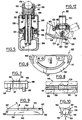
- - la figure 1 illustre en coupe une tête de trolleybus conforme à une première variante de l'invention, prête au fonctionnement, la position de remplacement du frotteur d'usure étant représentée en traits mixtes (partie mobile du berceau déverrouillée et basculée pour l'extraction instantanée du frotteur d'usure);
- - la figure 2 est une coupe transversale de la tête de la figure 1, la plan de coupe passant au niveau de l'axe d'oscillation sensiblement vertical du berceau, permettant de mieux comprendre comment est réalisé le maintien du frotteur d'usure sur la face de support et de contact associée;
- - la figure 3 est une vue en perspective d'un élément ressort, normalement porté par l'axe d'articulation de la partie mobile du berceau, dont la découpe permet un maintien correct du frotteur d'usure lorsque cette partie mobile est verrouillée sur le corps principal;
- - la figure 4 illustre en coupe une tête de trolleybus conforme à une deuxième variante de l'invention, prête au fonctionnement, la position de remplacement du frotteur d'usure étant représentée en traits mixtes (partie mobile du berceau déverrouillée et basculée pour l'extraction instantanée du frotteur d'usure);
- - la figure 5 est une coupe transversale de la tête de la figure 4, le plan de coupe passant au niveau de l'axe d'oscillation sensiblement vertical du berceau, permettant de mieux comprendre comment est réalisé le maintien du frotteur d'usure sur la face de support et de contact associé grâce à un appui direct de la partie mobile du berceau ;
- - la figure 6 est une vue en plan d'un fiasque latéral du corps principal de berceau, permettant en particulier de distinguer le palier oblong assurant un débattement de l'axe d'articulation de la partie mobile du berceau ;
- - les figures 7 et 8 illustrent respectivement en vue en bout et de dessus la platine du corps principal de berceau recevant les lamelles de contact contre lesquelles le frotteur d'usure est maintenu ;
- - les figures 9 et 10 sont des vues respectivement en plan et en bout d'un frotteur d'usure conforme à l'invention, destiné à équiper la tête de trolleybus perfectionnée illustrée aux figures précédentes ;
- - la figure 11 est une vue de dessus, à l'échelle agrandie, du ressort de torsion agissant sur l'axe d'articulation de la partie mobile du berceau en vue du maintien du frotteur d'usure contre la face de support et de contact en position verrouillée ;
- - la figure 12 illustre en coupe un détail d'une variante de la liaison entre perche et berceau, selon laquelle une articulation supplémentaire permet un effacement dudit berceau dans le cas où la tête de trolleybus s'échapperait de la ligne de captation et viendrait heurter une transversale portant cette ligne, et la figure 13 est la coupe correspondante selon XIII-XIII.
- - Figure 1 illustrates in section a trolleybus head according to a first variant of the invention, ready for operation, the replacement position of the wear shoe being shown in phantom (mobile part of the cradle unlocked and tilted for the instant wear wear removal);
- - Figure 2 is a cross section of the head of Figure 1, the cutting plane passing at the level of the substantially vertical axis of oscillation of the cradle, to better understand how is maintained the wear shoe on the associated support and contact face;
- - Figure 3 is a perspective view of a spring element, normally carried by the articulation axis of the movable part of the cradle, the cutout of which allows the wear friction shoe to be properly held when this movable part is locked on the main body;
- - Figure 4 illustrates in section a trolleybus head according to a second variant of the invention, ready for operation, the replacement position of the wear shoe being shown in phantom (mobile part of the cradle unlocked and tilted for the instant wear wear removal);
- - Figure 5 is a cross section of the head of Figure 4, the cutting plane passing at the level of the substantially vertical axis of oscillation of the cradle, to better understand how is maintained the wear shoe on the support face and associated contact thanks to a direct support of the mobile part of the cradle;
- - Figure 6 is a plan view of a lateral flange of the main body of the cradle, making it possible in particular to distinguish the oblong bearing ensuring a movement of the articulation axis of the movable part of the cradle;
- - Figures 7 and 8 respectively illustrate an end view and from above the plate of the main body of the cradle receiving the contact strips against which the wear shoe is held;
- - Figures 9 and 10 are respectively plan and end views of a wear shoe according to the invention, intended to equip the improved trolleybus head illustrated in the previous figures;
- - Figure 11 is a top view, on an enlarged scale, of the torsion spring acting on the articulation axis of the movable part of the cradle in order to maintain the wear friction against the support face and contact in locked position;
- - Figure 12 illustrates in section a detail of a variant of the connection between pole and cradle, according to which an additional articulation allows an erasing of said cradle in the event that the trolleybus head escapes from the pickup line and collides a transverse carrying this line, and Figure 13 is the corresponding section along XIII-XIII.
Les figures 1 et 2 illustrent une tête de trolleybus conforme à l'invention, telle que montée en bout de perche du trolleybus.Figures 1 and 2 illustrate a trolleybus head according to the invention, as mounted at the end of the trolleybus pole.
Conformément aux techniques classiques, la tête 1 présente un certain nombre d'organes constitutifs dont la disposition permet plusieurs degrés de liberté par rapport à la perche. On trouve ainsi un corps d'embout de perche 2, habituellement réalisé en une pièce moulée en aluminium, monté coaxialement (par collage ou autre moyen) sur l'extrémité d'un tube isolant 3 figurant l'extrémité de la perche dont le reste n'est pas représenté. Sur le corps d'embout de perche 2 est articulée une pièce 4, habituellement dénommée corps de berceau, pouvant pivoter autour d'un axe oblique 5, sur une plage angulaire prédéterminée (des butées non représentées limitent en principe ce pivotement à 90° de part et d'autre de la position médiane correspondant à une perche située dans le plan vertical de la ligne de captation). Sur la pièce 4 est monté un berceau 6 avec une liaison permettant une oscillation autour d'un axe sensiblement vertical 7, avec des butées non représentées pour limiter la plage angulaire d'oscillations, ledit berceau 6 pouvant également basculer autour d'un axe sensiblement horizontal. On notera que la liaison entre le berceau 6 et la pièce corps de berceau 4 n'est pas une liaison à rotule comme c'était fréquemment le cas dans les techniques antérieures, mais définit au contraire deux axes d'articulation déterminés, ce qui présente certains avantages sur lesquels on reviendra plus loin. A titre indicatif, les axes d'articulation 5, 7 forment entre eux un angle compris entre 15° et 25°, de façon à obtenir un comportement satisfaisant de la tête de trolleybus, même en cas de virage serré.In accordance with conventional techniques, the
Conformément à un aspect essentiel de l'invention, le berceau 6 comporte un corps principal 8 présentant une face de support et de contact 9 pour la partie inférieure d'un frotteur d'usure 10, lequel est utilisé pour la transmission du courant vers un câble 11 porté par la perche, par l'intermédiaire d'un shunt 12 raccordé au berceau ; ledit berceau comporte également une partie mobile 13 articulée, verrouillable sur le corps principal 8, et présentant une overture longitudinale pour le passage de la partie supérieure du frotteur d'usure 10.In accordance with an essential aspect of the invention, the cradle 6 comprises a
Ainsi, lorsque la partie mobile 13 est déverrouillée et dégagée du corps principal 8 du berceau, l'opérateur a un accès instantané au frotteur d'usure 10, ce qui permet un remplacement très rapide de celui- ci, tandis qu'en position de verrouillage de cette partie mobile, ledit frotteur d'usure 10 est parfaitement maintenu contre la face de support et de contact 9, par l'intermédiaire de moyens élastiquement déformables qui seront décrits plus en détail en référence à la figure 3, qui en donne une illustration particulièrement intéressante pour l'application considérée.Thus, when the
Du fait d'un montage du frotteur d'usure sans encastrement, ledit frotteur peut être aisément réalisé à partir d'un profilé de section uniforme, cette section apparaissant plus nettement sur la figure 2, ce qui permet d'avoir un mode de fabrication économique grâce à l'utilisation de techniques telles que le filage. Pour procéder au remplacement de ce frotteur d'usure, il suffit donc à l'opérateur de déverrouiller la partie mobile du berceau pour dégager à la main le frotteur d'usure à remplacer, et mettre en place instantanément un nouveau frotteur avant de verrouiller de nouveau ladite partie mobile : ces opérations sont donc particulièrement faciles pour l'opérateur, qui peut procéder au remplacement de la pièce d'usure dans un temps très court, et sans aucun outillage.Due to an assembly of the wear wiper without embedding, said wiper can be easily produced from a profile of uniform section, this section appearing more clearly in FIG. 2, which makes it possible to have a manufacturing method economical thanks to the use of techniques such as spinning. To replace this wear wiper, the operator just has to unlock the mobile part of the cradle to manually release the wear wiper to be replaced, and instantly put in place a new wiper before locking new said movable part: these operations are therefore particularly easy for the operator, who can replace the wearing part in a very short time, and without any tools.
Le mode de réalisation illustré ici comporte une partie mobile 13 de berceau articulée sur un axe fixe 14 porté par le corps principal 8 dudit berceau ; la pièce mobile 13 présente une configuration symétrique, avec une paire d'oreilles 15 à chacune de ses extrémitées, une paire étant prévue pour l'articulation, tandis que l'autre est prévue pour porter une patte de verrouillage élastique 16 pouvant coopérer en position de verrouillage avec une moulure 17 ménagée à cet effet sur le corps principal du berceau. La partie mobile du berceau présente une ouverture longitudinal 18, sensiblement rectangulaire, pour le passage de la partie supérieure du frotteur d'usure entre les deux flasques de la partie mobile prévues,conformément à l'habitude,pour le guidage latéral par rapport à la ligne de captation 19, ainsi que cela ressort plus clairement de la figure 2.The embodiment illustrated here comprises a
Le frotteur d'usure 10 présente ainsi en sa partie inférieure deux ailes longitudinales 20 définissant, vers le bas, la face dudit frotteur destinée à être appliquée contre la face de support et de contact 9, et, vers le haut, deux faces d'appui 21 qui reçoivent la force d'application des moyens élastiquement déformables qui sont disposés entre ces faces d'appui, et un rebord associé 22 prévu sur la partie mobile du berceau au voisinage de l'ouverture longitudinale 18.The
Les moyens élastiquement déformables sont avantageusement constitués par un élément unique 23 dont la forme est illustrée en perspective à la figure 3. Cet élément unique comporte deux branches ondulées 24 qui sont logées, en position de verrouillage de la partie mobile du berceau, entre les ailes longitudinales 20 du frotteur d'usure et les rebords 22 précités de ladite partie mobile. L'élément unique présente ainsi une forme générale rectangulaire, avec un évidement 25 correspondant au passage de la partie supérieure du frotteur d'usure, et, d'un côté, une patte de liaison 26 traversée par l'axe d'articulation de la partie mobile du berceau (schématisé par l'axe 27 sur la figure 3), et de l'autre côté une patte 28 permettant le maintien en position dudit élément 23 par un appui sur une portion transversale 29 de la partie mobile (visible sur la figure 1). Ce mode de réalisation des moyens élastiquement déformables est particulièrement simple et efficace dans l'application considérée, l'élément unique 23 étant ainsi monté à demeure sur la partie mobile du berceau, s'articulant avec celle-ci autour de l'axe 14, tout en présentant un certain débattement longitudinal permettant d'absorber une longueur excédentaire en position de verrouillage, grâce à l'appui glissant de la patte 28. Il n'y a ainsi aucun risque de perte de l'élément 23 au dégagement de la partie mobile du berceau, ni de mauvais positionnement dudit élément par rapport au frotteur d'usure, lorsque ladite partie mobile est rabattue pour son verrouillage. Il suffit donc pour l'opérateur de dégager la patte élastique 16 et de relever la partie mobile du berceau, pour avoir un accès direct et instantané au frotteur d'usure.The elastically deformable means advantageously consist of a
Le frotteur d'usure 10 est ainsi parfaitement positionné sur la face de support et de contact 9 du corps principal du berceau, avantageusement entre deux butées 30 dont la fonction est d'assurer le maintien dudit frotteur dans une direction longitudinale. Le fait que le frotteur d'usure 10 soit simplement posé sur la face de support et de contact 9 permet une réalisation de ladite face en pointes de diamant, disposition qui ne pouvait être adoptée avec la conception ancienne d'un encastrement glissant dudit frotteur d'usure. Les pointes de diamant viennent s'incruster légèrement dans la face en regard du frotteur d'ussure, et la multiplicité des points de contact obtenus assure une excellente transmission du courant entre ledit frotteur d'usure et le berceau ; ces pointes permettent de plus un rattrapage des tolérances pour la face de contact du frotteur d'usure, issu de moulage ou de filage d'un profilé en aggloméré de carbone chargé. La répartition régulière de ces points aura naturellement un effet favorable d'un point de vue thermique, l'échauffement au niveau du contact étant également réparti pour l'ensemble du frotteur d'usure.The
La structure du frotteur d'usure et de la face de support et de contact associée rend possible une disposition particulièrement avantageuse par sa compacité pour le shunt de liaison 12: le corps principal 8 du berceau présente en effet une portion centrale de connexion 31 pour le serrage des extrémités du shunt 12 au moyen de vis 32, ces extrémités s'étendant ainsi entre les flasques latéraux 33 du corps principal de berceau, puis dans l'alésage d'une douille 34 de la liaison articulée dudit berceau sur la pièce 4. Par ailleurs, on notera que cette douille 34 est entourée par un manchon 35, intérieur à une douille de guidage 36 dont la surface extérieure présente, de chaque côté, une rainure circulaire saillante 37 reçue dans une gorge correspondante 38, ménagée sur le flasque associé 33 vers l'intérieur du corps principal du berceau. Les pièces de frottement 35, 36 peuvent naturellement être réalisées en une pièce unique, par exemple à partir d'un matériau tel que celui commercialisé sous la dénomination ERTAFLUOR, qui présente de bonnes caractéristiques de glissement à des températures pouvant dépasser 120° C.The structure of the wear wiper and the associated support and contact face makes a particularly advantageous arrangement possible due to its compactness for the connecting shunt 12: the
Selon le même principe, la partie centrale du shunt 12 passera à l'intérieur d'un manchon central 39 (en acier inoxydable de préférence), au niveau de la liaison d'articulation avec le corps d'en bout de perche 2. Ce manchon 39, incorporé lors de la réalisation en fonderie de la partie corps de berceau 4, reçoit extérieurement deux douilles de frottement 40, de préférence, en un matériau présentant de bonnes caractéristiques de glissement, tel que celui commercialisé sous la dénomination ERTALON, car il suffit ici de supporter des températures ne dépassant pas 70° C. L'extrémité du shunt 12 se raccorde enfin sur une pièce de jonction électrique 41 assurant la connexion avec le câble 11.According to the same principle, the central part of the
La tête de trolleybus, ainsi réalisée conformément à l'invention, permet un démontage rapide et aisé, sans outils particuliers, pour le remplacement du frotteur d'usure, lequel peut être réalisé de façon particulièrement économique, sans nuire aucunement au contact électrique obtenu.The trolleybus head, thus produced in accordance with the invention, allows rapid and easy disassembly, without special tools, for the replacement of the wear shoe, which can be carried out in a particularly economical manner, without in any way harming the electrical contact obtained.
Il va de soi que diverses modifications pourraient être apportées au mode de réalisation représenté : en particulier, la section transversale du frotteur d'usure peut différer de celle représentée à la figure 2, et les moyens élastiquement déformables peuvent aussi présenter des structures sensiblement différentes de celle illustrée à la figure 3. On pourra également utiliser une structure différente pour les liaisons d'articulation traversées par le shunt, et plus particulièrement celle du berceau portant le frotteur d'usure, en prévoyant par exemple des douilles à lamelles ressorts de contact capables de transmettre du courant : ceci permet en particulier d'éviter une transmission du courant par le ressort, lorsque la partie mobile du berceau est seule en contact avec la ligne de captation (cas des croisements ou aiguillages).It goes without saying that various modifications could be made to the embodiment shown: in particular, the cross section of the wear shoe may differ from that shown in FIG. 2, and the elastically deformable means may also have structures that are substantially different from that illustrated in FIG. 3. It is also possible to use a different structure for the articulation links through which the shunt passes, and more particularly that of the cradle carrying the wear friction shoe, by providing, for example, lampholders with contact spring capable to transmit current: this makes it possible in particular to avoid transmission of current by the spring, when the movable part of the cradle is alone in contact with the pick-up line (case of crossings or switches).
La deuxième variante de la tête de trolleybus qui va maintenant être décrite en référence aux figures 4 à 13, comporte un certain nombre d'organes constitutifs analogues à ceux formant la tête de trolleybus qui vient d'être décrite. Par mesure de simplicité, les références utilisées pour ces organes dans la suite de la description correspondront aux références de la variante précédente augmentées du nombre 100.The second variant of the trolley bus head which will now be described with reference to FIGS. 4 to 13, comprises a certain number of constituent members similar to those forming the trolley bus head which has just been described. For simplicity, the references used for these members in the following description will correspond to the references of the previous variant increased by the number 100.
Figures 4 et 5, la tête 101 comporte un corps d'embout de perche 102 monté à l'extrémité d'un tube isolant 103 ; sur ce corps d'embout de perche 102 est articulé un corps de berceau 104 pouvant pivoter autour d'un axe oblique 105, sur une plage angulaire prédéterminée. Sur la pièce 104 est monté un berceau 106 avec une liaison permettant une oscillation autour d'un axe sensiblement vertical 107, ledit berceau 106 pouvant également basculer autour d'un axe sensiblement horizontal.Figures 4 and 5, the
Le berceau 106 comporte un corps principal 108 présentant une face de support et de contact 109 (sur laquelle il sera revenu ultérieurement) pour la face inférieure d'un frotteur d'usure 110, lequel est utilisé pour la transmission du courant vers un câble 111 porté par la perche, par l'intermédiaire d'un shunt 112 raccordé au berceau ; ledit berceau comporte également une partie mobile 113 articulée sur un axe 114 porté par le corps principal 108, et présentant une ouverture longitudinale pour le passage de la partie supérieure du frotteur d'usure 110. La pièce mobile 113 est de configuration symétrique, avec une paire d'oreilles 115 à chacune de ses extrémités, une paire étant prévue pour l'articulation, tandis que l'autre est prévue pour porter une patte de verrouillage élastique 116 pouvant coopérer en position de verrouillage avec une moulure 117 ménagée à cet effet sur le corps principal du berceau.The
Conformément à un aspect essentiel de la structure de cette tête de trolleybus, l'axe d'articulation 114 de la partie mobile du berceau est monté sur le corps principal 108 avec possiblité de débattement dans une direction sensiblement perpendiculaire à la face de support et de contact 109, la partie mobile 113 du berceau présentant, au voisinage de l'ouverture longitudinale 118 de celle-ci, un double rebord 122 en contact direct avec les bords supérieurs latéraux du frotteur d'usure 110 ; comme dans la variante précédente, les moyens élastiquement déformables sont prévus pour le maintien du frotteur d'usure 110 contre la face de support et de contact lorsque la partie mobile est verrouillée sur le corps principal, mais ces moyens comportent ici un organe ressort 142 agissant sur l'axe d'articulation 114 de façon à exercer sur la partie mobile 113 du berceau l'effort de maintien désiré.In accordance with an essential aspect of the structure of this trolleybus head, the
Ainsi que cela est mieux visible sur la figure 6, chacun des deux flasques latéraux 133 du corps principal 108 comporte ainsi un palier oblong 143 recevant l'extrémité associée de l'axe d'articulation 114. Il est à noter que ce flasque 133 est de réalisation symétrique, pour en simplifier la fabrication et éviter tout risque d'erreur au montage : on trouve ainsi un palier oblong 143 et une moulure 117 à chacune des extrémités du flasque, étant entendu que le palier oblong est indispensable au niveau de l'axe d'articulation 114 seulement, et que la moulure 117 est quant à elle indispensable pour coopérer avec le clip de verrouillage 116.As is better visible in FIG. 6, each of the two
Un tel montage confère à la partie mobile 113 un caractère flottant extrêmement intéressant, car c'est lui qui permet un appui direct par les rebords 122 sur le frotteur 110, ainsi que cela est particulièrement visible sur la figure 5. On conçoit aisément que, en cas d'interruption du contact électrique avec le frotteur 110 lorsque la tête passe au niveau d'appareillages de lignes du type mentionné plus haut, les joues de la partie mobile 113 assurent le cheminement direct du courant vers le frotteur 110, sans passer par un élément intermédiaire tel que l'élément ressort à branches ondulées 23 de la variante précédente. Les joues de la partie mobile 113 assurent ainsi une double fonction, c'est-à-dire le guidage de la ligne de captation 119, et le contact électrique pour le cheminement direct du courant.Such an assembly gives the
La figure 11 illustre un mode de réalisation possible pour le ressort de torsion 142 monté sur le corps principal 108 du berceau. Ce ressort est monté sur un axe 144 traversant les oreilles 145 d'une platine146 disposée entre les flasques latéraux 133 et dont la partie supérieure 109 constitue la face de support et de contact pour le frotteur d'usure 110. Ainsi montées, les deux branches libres d'extrémité 147 du ressort 142 sont en appui contre la face inférieure de la platine 146, tandis que la branche 148 exerce en permanence une pression d'application dirigée vers le bas sur l'axe d'articulation 114. Le ressort 142 tend ainsi toujours à déplacer l'axe 114 vers la partie inférieure du palier oblong 143. On a illustré ici un axe d'articulation 114 de section carrée : cet axe présente ainsi une arête vive 149 sur laquelle prend appui la branche 148 du ressort de torsion lorsque la partie mobile 113 du berceau est en position de verrouillage ; ceci définit un cran qui facilite le dégagement de la partie mobile du berceau et évite une retombée de celle-ci sur les mains de l'opérateur occupé à manipuler le frotteur d'usure.FIG. 11 illustrates a possible embodiment for the
Selon une possibilité avantageuse, l'organe de verrouillage de la partie mobile, qui est ici un clip 116, présente une capacité suffisante de déformation élastique pour remplir également, comme le ressort de torsion 142 mais dans une moindre mesure, une fonction de maintien élastique du frotteur d'usure 110 sur la face de support et de contact 109 lorsque la partie mobile est verrouillée sur le corps principal. La partie mobile du berceau est alors doublement flottante.According to an advantageous possibility, the locking member of the mobile part, which is here a
La face de support et de contact 109 est avantageusement constituée par des lamelles de contact présentant une certaine élasticité, et disposée sur la face supérieure du corps principal du berceau. Ainsi qu'illustré aux figures 7 et 8, deux plaquettes 150 sont disposées dans une rainure longitudinale 151 de la platine 146 du corps principal du berceau ; ces deux plaquettes sont disposées de part et d'autre d'une portion centrale de connexion 131 du corps principal de berceau prévue pour recevoir l'extrémité du shunt 112 passant par les liaisons d'articulation du berceau. Ces lamelles de contact donnent de meilleurs résultats que les pointes de diamant prévues sur la face de support de contact de la tête conforme à la variante précédente : leur souplesse assure à la fois un bon contact, et permet un rattrapage des tolérances pour la face de contact du frotteur d'usure, lequel est issu de moulage ou de filage d'un profilé en aggloméré de carbone char- gé. The support and
Le frotteur d'usure 110 est ainsi parfaitement positionné sur la face de support et de contact 109, par exemple entre deux butées 130 dont la fonction est d'assurer le maintien dudit frotteur dans une direction longitudinale (on pourrait naturellement prévoir une face supérieure parfaitement plane 152 pour la platine 146, ainsi qu'illustré aux figures 7 et 8, auquel cas le maintien du frotteur peut être simplement assuré par deux nervures transversales ménagées sur la partie mobile 113 du berceau, ce que facilite l'usinage de la rainure 151).The
Comme dans la variante précédente, les extrémités du shunt 112 sont fixées au moyen de vis 132 sur la portion centrale de connexion 131, ces extrémités s'étendant ainsi entre les flasques latéraux 133 du corps principal, puis dans l'alésage d'une douille 134 de la liaison articulée du berceau sur la pièce 104 ; cette douille 134 est par ailleurs entourée par une pièce 135 dont la surface extérieure présente de chaque côté une gorge circulaire 138 dans laquelle passe une rainure circulaire saillante 137 ménagée sur chacun des flasques latéraux 133 (on notera que, dans la variante précédente, la disposition était inversée, avec une gorge sur chaque flasque latéral et une rainure circulaire sur la pièce mobile). La partie centrale du shunt 112 passe ensuite à l'intérieur d'un manchon 139 au niveau de la liaison d'articulation avec le corps d'embout de perche 102, ledit manchon recevant extérieurement deux douilles de frottement 140 ; l'extrémité du shunt 112 se raccorde enfin sur une pièce de jonction électrique 141 assurant la connexion avec le câble 111.As in the previous variant, the ends of the
Les figures 9 et 10 illustrent la structure d'un frotteur d'usure destiné à équiper la tête de trolleybus qui vient d'être décrite. Ce frotteur est constitué par un corps allongé de section transversale essentiellement constante, ladite section ayant ici la forme d'un trapèze dont la petite base correspond à une face plane inférieure 153 qui doit être appliquée contre la face de support et de contact du corps principal du berceau. La forme de cette section transversale est doublement intéressante : d'abord elle réduit la surface du frotteur en appui direct sur les lamelles, ce qui permet de s'assurer que la face inférieure 153 est toujours en contact avec les lamelles sans reposer sur la face supérieure adjacente 152 de la platine ; de plus, il est possible de réaliser une économie de matière d'au moins 20 %, tout en ayant un comportement optimal du frotteur à l'usure grâce au parallélisme de facettes latérales.Figures 9 and 10 illustrate the structure of a wear shoe intended to equip the trolleybus head which has just been described. This wiper is constituted by an elongated body of essentially constant cross section, said section here having the shape of a trapezium whose small base corresponds to a lower
Le frotteur comporte ainsi deux facettes parallèles 154 adjacentes aux bords supérieurs latéraux sur lesquels s'appuient les rebords 122 de la partie mobile 113 en position de verrouillage, puis deux faces inclinées 155 rejoignant la face plane inférieure 153. Chacune des faces inclinées 155 forme de préférence un angle d'environ 30° avec la facette 154 adjacente (angle y sur la figure 10). Les faces d'extrémité 156 sont quant à elles essentiellement planes et perpendiculaires à la direction générale du corps allongé, à l'exception de leur bord supérieur 157 qui est avantageusement incliné par rapport à cette direction, selon un angle (figure 9) qui est ici d'environ 30°.The wiper thus has two
Comme pour la variante précédente, la tête de trolleybus ainsi réalisée permet un démontage rapide et aisé, sans outils particuliers, pour le remplacement du frotteur d'usure, lequel peut être réalisé de façon particulièrement économique, sans nuire aucunement au contact électrique obtenu.As with the previous variant, the trolleybus head thus produced allows rapid and easy disassembly, without special tools, for the replacement of the wear shoe, which can be produced in a particularly economical manner, without in any way harming the electrical contact obtained.
Il va de soi que diverses modifications pourraient être apportées au mode de réalisation représenté : en particulier, la section transversale du frotteur d'usure peut différer de celle représentée à la figure 10, et les moyens élastiquement déformables peuvent aussi présenter des structures sensiblement différentes de celles illustrées aux figures 7 et 8. On pourra enfin également utiliser une structure différente pour les liaisons d'articulation traversées par le shunt, et plus particulièrement celles du berceau portant le frotteur d'usure.It goes without saying that various modifications could be made to the embodiment shown: in particular, the cross section of the wear shoe may differ from that shown in FIG. 10, and the elastically deformable means may also have structures that are substantially different from those illustrated in Figures 7 and 8. Finally, we can also use a different structure for the articulation connections crossed by the shunt, and more particularly those of the cradle carrying the wear shoe.
Sur les figures 12 et 13, on a illustré une variante de la liaison entre le berceau 106 et la pièce 104, et plus particulièrement au niveau de la douille 134 visible en figure 4. Selon cette variante, la douille 134 présente un degré de liberté supplémentaire, grâce à un montage articulé sur la pièce 104. La douille 134 est en effet montée sur un cavalier 158 en forme de U renversé au moyen d'un écrou 159 et d'une rondelle 160 ; le cavalier 158 est monté oscillant sur un axe fixe 161, et un ressort 162 assure le maintien dudit cavalier contre une butée transversale 163. Le ressort 162 est ici un ressort de torsion monté sur l'axe fixe 161, et dont les deux branches d'extrémité 164 sont chacune reçues dans une encoche associée 165 prévue sur la pièce 104, mais on pourrait aussi bien utiliser un système de cliquet à bille avec ressort taré travaillant en compression. De cette façon, si la tête de trolleybus s'échappe de la ligne associée, le moindre choc avec une transversale qui porte cette ligne provoque automatiquement l'effacement de la tête (voir la position schématisée en traits mixtes sur la figure 12), écartant ainsi tout risque de rupture de pièce (la pièce 135 de la tête par exemple) ou pire encore d'arrachement de la transversale ou de la ligne.In FIGS. 12 and 13, a variant of the connection between the
Claims (23)
Priority Applications (1)
| Application Number | Priority Date | Filing Date | Title |
|---|---|---|---|
| AT86402553T ATE50405T1 (en) | 1985-11-20 | 1986-11-18 | PANTOGRAPH HEAD FOR Trolleybus. |
Applications Claiming Priority (4)
| Application Number | Priority Date | Filing Date | Title |
|---|---|---|---|
| FR8517165 | 1985-11-20 | ||
| FR8517165A FR2590210B1 (en) | 1985-11-20 | 1985-11-20 | TROLLEYBUS HEAD |
| FR8608936 | 1986-06-20 | ||
| FR8608936A FR2600287B2 (en) | 1985-11-20 | 1986-06-20 | TROLLEYBUS HEAD |
Publications (2)
| Publication Number | Publication Date |
|---|---|
| EP0226497A1 EP0226497A1 (en) | 1987-06-24 |
| EP0226497B1 true EP0226497B1 (en) | 1990-02-14 |
Family
ID=26224833
Family Applications (1)
| Application Number | Title | Priority Date | Filing Date |
|---|---|---|---|
| EP86402553A Expired - Lifetime EP0226497B1 (en) | 1985-11-20 | 1986-11-18 | Current collector for a trolley bus |
Country Status (5)
| Country | Link |
|---|---|
| US (1) | US4742185A (en) |
| EP (1) | EP0226497B1 (en) |
| CA (1) | CA1304461C (en) |
| DE (1) | DE3669038D1 (en) |
| FR (1) | FR2600287B2 (en) |
Cited By (5)
| Publication number | Priority date | Publication date | Assignee | Title |
|---|---|---|---|---|
| CZ304075B6 (en) * | 2012-08-07 | 2013-09-25 | Faiveley Transport Lekov A.S. | Housing of trolleybus trolley bearing |
| DE202015100622U1 (en) | 2015-02-10 | 2016-05-11 | Conductix-Wampfler Gmbh | Pantograph and conductor rail system |
| DE202015100623U1 (en) | 2015-02-10 | 2016-05-11 | Conductix-Wampfler Gmbh | Pantograph and conductor rail system |
| DE102015101849A1 (en) | 2015-02-10 | 2016-08-11 | Conductix-Wampfler Gmbh | Pantograph and conductor rail system |
| DE102015101848A1 (en) | 2015-02-10 | 2016-08-11 | Conductix-Wampfler Gmbh | Pantograph and conductor rail system |
Families Citing this family (2)
| Publication number | Priority date | Publication date | Assignee | Title |
|---|---|---|---|---|
| EP0605214B1 (en) * | 1992-12-28 | 1997-11-19 | Hitachi, Ltd. | High speed low noise current collecting equipment |
| FR2855111B1 (en) | 2003-05-20 | 2006-02-24 | Railtech Int | DEVICE, IN PARTICULAR HEAD, CAPTURING ELECTRICITY FOR A VEHICLE SUCH AS A TROLLEYBUS OR A TRAMWAY |
Family Cites Families (8)
| Publication number | Priority date | Publication date | Assignee | Title |
|---|---|---|---|---|
| GB150120A (en) * | 1919-06-20 | 1920-09-02 | British Insulated & Helsby Cables Ltd | Improvements in and connected with electricity collectors |
| US2185270A (en) * | 1938-10-05 | 1940-01-02 | Ohio Rrass Company | Current collecting device |
| US2508531A (en) * | 1949-02-14 | 1950-05-23 | Nat Bronze & Aluminum Fdry Co | Current collector |
| DE974463C (en) * | 1950-08-18 | 1961-01-05 | Hans Dipl-Ing Koehl | Current collector head for electric, especially rail-less vehicles with pantographs |
| CH359463A (en) * | 1958-05-17 | 1962-01-15 | Bbc Brown Boveri & Cie | Detachable contact strip attachment in the pantograph head of pantographs in electric vehicles |
| FR2320204A1 (en) * | 1975-08-07 | 1977-03-04 | Gennevilliers Acieries | Electrical pickup for overhead cables - has overhead arm with two conducting shoes fixed about different axes to balance arm connected by rubber bush to mounting on overhead arm |
| JPS5234004U (en) * | 1975-09-02 | 1977-03-10 | ||
| US4431933A (en) * | 1978-10-09 | 1984-02-14 | Takaichi Mabuchi | Brush holding device |
-
1986
- 1986-06-20 FR FR8608936A patent/FR2600287B2/en not_active Expired
- 1986-11-18 DE DE8686402553T patent/DE3669038D1/en not_active Expired - Lifetime
- 1986-11-18 US US06/932,466 patent/US4742185A/en not_active Expired - Lifetime
- 1986-11-18 EP EP86402553A patent/EP0226497B1/en not_active Expired - Lifetime
- 1986-11-19 CA CA000523377A patent/CA1304461C/en not_active Expired - Fee Related
Cited By (6)
| Publication number | Priority date | Publication date | Assignee | Title |
|---|---|---|---|---|
| CZ304075B6 (en) * | 2012-08-07 | 2013-09-25 | Faiveley Transport Lekov A.S. | Housing of trolleybus trolley bearing |
| DE202015100622U1 (en) | 2015-02-10 | 2016-05-11 | Conductix-Wampfler Gmbh | Pantograph and conductor rail system |
| DE202015100623U1 (en) | 2015-02-10 | 2016-05-11 | Conductix-Wampfler Gmbh | Pantograph and conductor rail system |
| DE102015101849A1 (en) | 2015-02-10 | 2016-08-11 | Conductix-Wampfler Gmbh | Pantograph and conductor rail system |
| DE102015101848A1 (en) | 2015-02-10 | 2016-08-11 | Conductix-Wampfler Gmbh | Pantograph and conductor rail system |
| DE102015101848B4 (en) * | 2015-02-10 | 2021-02-11 | Conductix-Wampfler Gmbh | Pantograph and conductor rail system |
Also Published As
| Publication number | Publication date |
|---|---|
| CA1304461C (en) | 1992-06-30 |
| DE3669038D1 (en) | 1990-03-22 |
| EP0226497A1 (en) | 1987-06-24 |
| FR2600287A2 (en) | 1987-12-24 |
| FR2600287B2 (en) | 1988-10-21 |
| US4742185A (en) | 1988-05-03 |
Similar Documents
| Publication | Publication Date | Title |
|---|---|---|
| EP0058438A2 (en) | Bicycle pedal allowing the attachment of a shoe in a preset position, and cyclist's shoe adapted for this pedal | |
| CH638996A5 (en) | SET OF A SHOE AND A SKI FIXED TO EACH OTHER. | |
| EP0134595B1 (en) | Ski boot | |
| EP0226497B1 (en) | Current collector for a trolley bus | |
| FR2899857A1 (en) | Windshield wiper arm disengaging device for motor vehicle, has release plate maintaining wiper arm in active sweeping position, and deformed by buckling, where wiper arm is operated between active sweeping position and disengaged position | |
| EP2520477A1 (en) | Rapid locking pin for use on a cycle | |
| EP1170203A1 (en) | Bicycle pedal with adjustable positions | |
| EP0380597A1 (en) | Braking device for skates and skate boards | |
| FR2891762A1 (en) | Manually-operated tile cutter has articulated separator for cut portions of tile operated by magnet | |
| EP0056228A2 (en) | Locking pin with a head and annular retaining means | |
| EP0289490B1 (en) | Snap hook for use in climbing, pot holing or similar activities | |
| EP1065771A1 (en) | Rung or rail for cable ladder, cable ladder and mounting method | |
| FR2561502A1 (en) | Device for fastening a shoe onto a pedal and component parts of the said device | |
| FR2760375A1 (en) | Snowshoe with boot held on pivoting plate | |
| FR2526382A1 (en) | Windscreen-wiper esp. for cars - comprises pressure arm and blade-carrier which are both pivotally attached to reciprocating mounting | |
| EP2009158A1 (en) | Braking device, heald frame equipped with such a braking device and loom equipped with such a frame | |
| FR2598934A1 (en) | SECURITY FIXING OF A SHOE ON A SKI | |
| CA2254576A1 (en) | Abrasive rail saw | |
| EP0199628B1 (en) | Safety stirrup for horse riding | |
| EP0951411B1 (en) | Motor vehicle wiper comprising a spring for generating wiping pressure | |
| FR2642656A1 (en) | SAFETY FASTENING FOR SKI INTENDED TO MAINTAIN THE FRONT OF A SKI SHOE | |
| FR2590210A1 (en) | Trolley bus head | |
| EP0159245A1 (en) | Windshield wiping device | |
| EP0226479A1 (en) | Heel holder, particularly for a safety ski binding | |
| EP4096972B1 (en) | Small-area wiping |
Legal Events
| Date | Code | Title | Description |
|---|---|---|---|
| PUAI | Public reference made under article 153(3) epc to a published international application that has entered the european phase |
Free format text: ORIGINAL CODE: 0009012 |
|
| AK | Designated contracting states |
Kind code of ref document: A1 Designated state(s): AT BE CH DE ES FR GB GR IT LI LU NL SE |
|
| 17P | Request for examination filed |
Effective date: 19870817 |
|
| 17Q | First examination report despatched |
Effective date: 19881221 |
|
| GRAA | (expected) grant |
Free format text: ORIGINAL CODE: 0009210 |
|
| ITF | It: translation for a ep patent filed |
Owner name: CON LOR S.R.L. |
|
| AK | Designated contracting states |
Kind code of ref document: B1 Designated state(s): AT BE CH DE ES FR GB GR IT LI LU NL SE |
|
| PG25 | Lapsed in a contracting state [announced via postgrant information from national office to epo] |
Ref country code: SE Effective date: 19900214 Ref country code: NL Effective date: 19900214 Ref country code: GR Free format text: LAPSE BECAUSE OF FAILURE TO SUBMIT A TRANSLATION OF THE DESCRIPTION OR TO PAY THE FEE WITHIN THE PRESCRIBED TIME-LIMIT Effective date: 19900214 Ref country code: GB Effective date: 19900214 Ref country code: AT Effective date: 19900214 |
|
| REF | Corresponds to: |
Ref document number: 50405 Country of ref document: AT Date of ref document: 19900215 Kind code of ref document: T |
|
| REF | Corresponds to: |
Ref document number: 3669038 Country of ref document: DE Date of ref document: 19900322 |
|
| PG25 | Lapsed in a contracting state [announced via postgrant information from national office to epo] |
Ref country code: ES Free format text: LAPSE BECAUSE OF FAILURE TO SUBMIT A TRANSLATION OF THE DESCRIPTION OR TO PAY THE FEE WITHIN THE PRESCRIBED TIME-LIMIT Effective date: 19900525 |
|
| NLV1 | Nl: lapsed or annulled due to failure to fulfill the requirements of art. 29p and 29m of the patents act | ||
| GBV | Gb: ep patent (uk) treated as always having been void in accordance with gb section 77(7)/1977 [no translation filed] | ||
| R20 | Corrections of a patent specification |
Effective date: 19900626 |
|
| PG25 | Lapsed in a contracting state [announced via postgrant information from national office to epo] |
Ref country code: LU Free format text: LAPSE BECAUSE OF NON-PAYMENT OF DUE FEES Effective date: 19901130 |
|
| PLBE | No opposition filed within time limit |
Free format text: ORIGINAL CODE: 0009261 |
|
| STAA | Information on the status of an ep patent application or granted ep patent |
Free format text: STATUS: NO OPPOSITION FILED WITHIN TIME LIMIT |
|
| 26N | No opposition filed | ||
| ITTA | It: last paid annual fee | ||
| PGFP | Annual fee paid to national office [announced via postgrant information from national office to epo] |
Ref country code: FR Payment date: 20050831 Year of fee payment: 20 |
|
| PGFP | Annual fee paid to national office [announced via postgrant information from national office to epo] |
Ref country code: DE Payment date: 20051107 Year of fee payment: 20 |
|
| PGFP | Annual fee paid to national office [announced via postgrant information from national office to epo] |
Ref country code: CH Payment date: 20051111 Year of fee payment: 20 |
|
| PGFP | Annual fee paid to national office [announced via postgrant information from national office to epo] |
Ref country code: IT Payment date: 20051118 Year of fee payment: 20 |
|
| PGFP | Annual fee paid to national office [announced via postgrant information from national office to epo] |
Ref country code: BE Payment date: 20051208 Year of fee payment: 20 |
|
| REG | Reference to a national code |
Ref country code: CH Ref legal event code: PL |
|
| BE20 | Be: patent expired |
Owner name: S.A. *DELACHAUX Effective date: 20061118 |