EP0225899B1 - Vorrichtung zum schliessen und öffnen der überdeckung einer fläche - Google Patents
Vorrichtung zum schliessen und öffnen der überdeckung einer fläche Download PDFInfo
- Publication number
- EP0225899B1 EP0225899B1 EP86903403A EP86903403A EP0225899B1 EP 0225899 B1 EP0225899 B1 EP 0225899B1 EP 86903403 A EP86903403 A EP 86903403A EP 86903403 A EP86903403 A EP 86903403A EP 0225899 B1 EP0225899 B1 EP 0225899B1
- Authority
- EP
- European Patent Office
- Prior art keywords
- screw
- helical
- cover
- supporting rod
- fixed
- Prior art date
- Legal status (The legal status is an assumption and is not a legal conclusion. Google has not performed a legal analysis and makes no representation as to the accuracy of the status listed.)
- Expired - Lifetime
Links
- 230000000750 progressive effect Effects 0.000 claims description 2
- 229910000831 Steel Inorganic materials 0.000 description 3
- 239000010959 steel Substances 0.000 description 3
- 241000251556 Chordata Species 0.000 description 1
- 230000000694 effects Effects 0.000 description 1
- 210000000056 organ Anatomy 0.000 description 1
- 230000009182 swimming Effects 0.000 description 1
Images


Classifications
-
- E—FIXED CONSTRUCTIONS
- E04—BUILDING
- E04B—GENERAL BUILDING CONSTRUCTIONS; WALLS, e.g. PARTITIONS; ROOFS; FLOORS; CEILINGS; INSULATION OR OTHER PROTECTION OF BUILDINGS
- E04B7/00—Roofs; Roof construction with regard to insulation
- E04B7/16—Roof structures with movable roof parts
- E04B7/166—Roof structures with movable roof parts characterised by a translation movement of the movable roof part, with or without additional movements
-
- E—FIXED CONSTRUCTIONS
- E04—BUILDING
- E04H—BUILDINGS OR LIKE STRUCTURES FOR PARTICULAR PURPOSES; SWIMMING OR SPLASH BATHS OR POOLS; MASTS; FENCING; TENTS OR CANOPIES, IN GENERAL
- E04H15/00—Tents or canopies, in general
- E04H15/18—Tents having plural sectional covers, e.g. pavilions, vaulted tents, marquees, circus tents; Plural tents, e.g. modular
-
- E—FIXED CONSTRUCTIONS
- E04—BUILDING
- E04H—BUILDINGS OR LIKE STRUCTURES FOR PARTICULAR PURPOSES; SWIMMING OR SPLASH BATHS OR POOLS; MASTS; FENCING; TENTS OR CANOPIES, IN GENERAL
- E04H3/00—Buildings or groups of buildings for public or similar purposes; Institutions, e.g. infirmaries or prisons
- E04H3/10—Buildings or groups of buildings for public or similar purposes; Institutions, e.g. infirmaries or prisons for meetings, entertainments, or sports
- E04H3/14—Gymnasiums; Other sporting buildings
- E04H3/16—Gymnasiums; Other sporting buildings for swimming
- E04H3/165—Gymnasiums; Other sporting buildings for swimming having movable parts
Definitions
- the invention relates to a device for covering or uncovering a surface, in particular a large surface, by means of a cover.
- the cover is rigid, as is for example the case of a blind, it is further limited in width.
- the invention overcomes these drawbacks. It relates to a device intended to cover or discover a surface, in particular a large surface, by means of a flexible or rigid cover which is easy to construct, reliable and allows to ensure perfect coverage of the surface to be covered.
- Figure 1 is a simplified embodiment of the invention, suitable for a rigid cover such as for example a curtain.
- Figure 2 shows a detail of the characteristic sleeve of the invention while Figure 3 is a sectional view of the same sleeve.
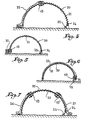
- Figure 4 is a schematic sectional representation of a device according to the invention for covering a curved surface, such as a sports hall, or even a greenhouse;
- Figures 5 and 6 show the same set respectively in position open ( Figure 5) and in the fully closed position ( Figure 6).
- Figure 7 is another embodiment according to Figure 4 wherein the surface is covered by a cover in two flexible parts.
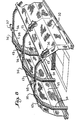
- FIG. 8 shows in summary perspective view a sports hall comprising a tennis court covered in accordance with the invention.
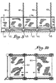
- Figures 9 and 10 show another embodiment of the invention for covering vertical walls, such as walls, windows or the like.
- the assembly includes a crank (1) which actuates a bevel gear (2) whose output shaft (3) is fitted on a nozzle ( 4).
- a crank (1) which actuates a bevel gear (2) whose output shaft (3) is fitted on a nozzle ( 4).
- On this end piece (4) is fixed the end (5) of a helical screw (6) which surrounds a rigid rod (7) of which one end (8) is mounted idly in a bore (9) provided for this effect in the nozzle (4) and the other end (10) of which is also mounted loose in an orifice (11) provided for this purpose in a wall (12).
- a coaxial sleeve (13) slides on the characteristic helical screw (6), for example in a cylindrical PVC tube whose internal diameter is slightly greater than the external diameter of the screw (6).
- This sleeve (13) has at its center a rigid axis (14), fixed by two bolts (15, 16), off-center with respect to the center of the sleeve (13) like a cord.
- the crank (1) is actuated in the direction indicated by the arrow, the end piece (4) is rotated, which consequently turns the screw (6) around the support rod (7).
- the axes (14, 14 ') slide along the screw (6) and thus cause the advancement of the sleeve (13) and its counterpart (13 ').
- the curtain which is for example rigid is moved from a first position to a second position and vice versa as indicated by the arrows.
- the surface to be covered is curved.
- the support rod (20) is curved and the helical screw (21) follows the shape of this rod.
- the cover to be deployed (22) formed in a single flexible part is fixed to the sleeve (13) and the end of the screw (21) secured to the end piece (24) is actuated by an electric motor. (25).
- Figure 5 shows the cover (22) fully folded, while in Figure 4 this same cover covers only half this surface, and finally in Figure 6 the entire surface.
- the support rod (20) consists of a steel bar fifteen millimeters in diameter.
- the helical screw (21) has an outside diameter of forty millimeters and a pitch also of forty millimeters; this screw is produced in a five-millimeter cylindrical steel torus.
- the sliding sleeve (13) is produced in a PVC tube whose internal diameter is fifty three millimeters and whose length is twenty centimeters.
- the characteristic rigid axis (14) has a diameter of six millimeters and is offset by fifteen millimeters.
- the cover is formed in two parts respectively (26) and (27) disposed on each side of the curved support rod (20). The end of each of these parts (26) and (27) is connected to a sleeve (13) and (13 ').
- the screw pitch of the helical screw (21) is reversed in the part on the left relative to the screw pitch on the right.
- FIG. 8 represents a more complex embodiment of the invention intended to cover the beams (30) of a sports hall.
- the cover is formed in two parts (31, 32) deployed on each side to meet in the center in the vicinity of the bevel gear (33, 34), the thread of the helical screw (35) being reversed with respect to the pitch of the screw (36).
- a motor (37) drives a shaft (38) and by the references (33, 34) the characteristic helical screws (35, 36).
- the device according to the invention is intended to cover a vertical surface, such as for example a window or a wall.
- a single electric motor for example a geared motor (40) drives a control shaft (41) which actuates bevel gears (42, 43, 44, 45) which, at in turn, drive the end pieces (46, 47, 48, 49) on which are fixed the ends of a plurality of vertical helical springs (50, 51, 52, 53) coaxial with rigid rods not shown.
- the characteristic rigid axis is simply placed between the support rod and the helical screw, so that there is no need to use a sleeve.
- the cover consists of two flexible panels (60, 61) which, as the case may be, approach or move away.
- the device according to the invention has many advantages over those known to date since it is easy to build, easy to operate, reliable, and since it makes it possible to cover either by means of flexible or rigid covers.
Landscapes
- Engineering & Computer Science (AREA)
- Architecture (AREA)
- Civil Engineering (AREA)
- Structural Engineering (AREA)
- Physics & Mathematics (AREA)
- Electromagnetism (AREA)
- Transmission Devices (AREA)
- Orthopedics, Nursing, And Contraception (AREA)
- Tents Or Canopies (AREA)
Claims (9)
dadurch gekennzeichnet, daß die Muffe (13) in einem Radialquerschnitt einen steifen Bolzen (14) aufweist, der längs einer Kreissehne angeordnet ist und der im Hinblick auf den Mittelpunkt der Muffe (13) versetzt ist, wobei der steife Bolzen (14) zwischen der Stützstange (7, 20) und dem koaxialen schraubenlinienförmigen Element (6, 21, 35, 36) derart gefangen ist, daß er längs des Elements (6, 21, 35, 36) gleiten kann.
Priority Applications (1)
| Application Number | Priority Date | Filing Date | Title |
|---|---|---|---|
| AT86903403T ATE50017T1 (de) | 1985-05-23 | 1986-05-22 | Vorrichtung zum schliessen und oeffnen der ueberdeckung einer flaeche. |
Applications Claiming Priority (2)
| Application Number | Priority Date | Filing Date | Title |
|---|---|---|---|
| FR8508001 | 1985-05-23 | ||
| FR8508001A FR2582227B1 (fr) | 1985-05-23 | 1985-05-23 | Dispositif pour recouvrir ou decouvrir une surface au moyen d'une couverture |
Publications (2)
| Publication Number | Publication Date |
|---|---|
| EP0225899A1 EP0225899A1 (de) | 1987-06-24 |
| EP0225899B1 true EP0225899B1 (de) | 1990-01-31 |
Family
ID=9319615
Family Applications (1)
| Application Number | Title | Priority Date | Filing Date |
|---|---|---|---|
| EP86903403A Expired - Lifetime EP0225899B1 (de) | 1985-05-23 | 1986-05-22 | Vorrichtung zum schliessen und öffnen der überdeckung einer fläche |
Country Status (10)
| Country | Link |
|---|---|
| US (1) | US4832104A (de) |
| EP (1) | EP0225899B1 (de) |
| JP (1) | JPS63500316A (de) |
| DE (1) | DE3668652D1 (de) |
| ES (1) | ES8704085A1 (de) |
| FR (1) | FR2582227B1 (de) |
| GR (1) | GR861327B (de) |
| PT (1) | PT82628B (de) |
| TN (1) | TNSN86079A1 (de) |
| WO (1) | WO1986007110A1 (de) |
Families Citing this family (19)
| Publication number | Priority date | Publication date | Assignee | Title |
|---|---|---|---|---|
| US4926922A (en) * | 1987-12-04 | 1990-05-22 | Topia Industry Co., Ltd. | Curtain drawing device |
| AU672917B2 (en) * | 1993-08-24 | 1996-10-17 | Gabba Sporting Products Pty Ltd | Demountable enclosure |
| FR2748381B1 (fr) * | 1996-05-13 | 1998-06-12 | Un Point Trois | Dispositif de support de rideaux |
| US6648050B1 (en) | 1997-11-04 | 2003-11-18 | Andrew J. Toti | Spring drive system and window cover |
| US6024156A (en) * | 1998-10-05 | 2000-02-15 | Marikon Resources, Inc. | Curtain drawing apparatus |
| US6389757B1 (en) * | 1999-12-14 | 2002-05-21 | Degarie Claude J. | Clarifier cover |
| US6612079B2 (en) | 2000-06-21 | 2003-09-02 | Degarie Claude J. | Clarifier cover |
| US20040111969A1 (en) * | 2001-04-04 | 2004-06-17 | Davut Kaya | Opening - closing mechanism |
| CA2381602C (en) * | 2002-04-12 | 2005-05-17 | Claude J. Degarie | Clarifier cover |
| US20060000565A1 (en) * | 2004-06-30 | 2006-01-05 | Franchel Et Compagnie, Societe Anonyme | Device for opening and closing a curtain, notably in order to automate the phases of opening and closing of the curtain |
| DE202009010894U1 (de) * | 2009-08-19 | 2009-12-24 | Geller, Wolfgang Peter | Transportabler Lichtmanipulator |
| US9095907B2 (en) * | 2012-09-17 | 2015-08-04 | Qmotion Incorporated | Drapery tube incorporating batteries within the drapery tube, with a stop for facilitating the loading and unloading of the batteries |
| US9540873B1 (en) * | 2012-12-05 | 2017-01-10 | MCD Innovations, Inc. | Laterally repositionable roller shade |
| US9999313B2 (en) * | 2013-04-11 | 2018-06-19 | Current Products Corp. | Motorized drapery apparatus, system and method of use |
| US10285527B2 (en) * | 2013-07-19 | 2019-05-14 | Current Products Corp. | Motorized drapery apparatus with batteries positioned in the brackets |
| US20150218791A1 (en) * | 2014-02-03 | 2015-08-06 | Robert A. Johnson | Screened lanai |
| US9801486B2 (en) | 2014-05-19 | 2017-10-31 | Current Products Corp. | Crossover bracket for drapery |
| US11457763B2 (en) | 2019-01-18 | 2022-10-04 | Current Products Corp. | Stabilized rotating drapery rod ring system |
| US12123457B2 (en) | 2020-06-03 | 2024-10-22 | Current Products Company, LLC | Splice connector system for architectural covering support rods |
Family Cites Families (11)
| Publication number | Priority date | Publication date | Assignee | Title |
|---|---|---|---|---|
| DE199302C (de) * | ||||
| FR775091A (fr) * | 1934-03-20 | 1934-12-19 | Tringles de rideaux | |
| US2616499A (en) * | 1949-04-08 | 1952-11-04 | Harley B Eckles | Fireplace screen |
| CH372805A (de) * | 1958-05-28 | 1963-10-31 | Berbalk Eleonore | Zugvorrichtung für Vorhänge, Gardinen und dergleichen |
| US3208507A (en) * | 1963-06-24 | 1965-09-28 | Frank J Breen | Traverse louver for window openings and the like |
| GB1185435A (en) * | 1968-08-06 | 1970-03-25 | Nicholas Benjamin Popil | An Enclosure Having an Opening Covered by a Cover. |
| CH511384A (de) * | 1970-08-26 | 1971-08-15 | Jakob Gilgen Maschinen Und App | Schieberkurvengetriebe |
| FR2398155A1 (fr) * | 1977-07-19 | 1979-02-16 | Milinic Vojin | Couverture mobile permettant de couvrir et decouvrir en quelques minutes un batiment |
| FR2444763A1 (fr) * | 1978-12-19 | 1980-07-18 | Milinic Vojin | Couverture variable pour batiments et terrains |
| US4280306A (en) * | 1979-06-04 | 1981-07-28 | Vojin Milinic | Convertible enclosure for buildings and areas |
| FR2497860A1 (fr) * | 1981-01-09 | 1982-07-16 | Javoise Jean Claude | Couverture amovible |
-
1985
- 1985-05-23 FR FR8508001A patent/FR2582227B1/fr not_active Expired
-
1986
- 1986-05-22 WO PCT/FR1986/000172 patent/WO1986007110A1/fr not_active Ceased
- 1986-05-22 EP EP86903403A patent/EP0225899B1/de not_active Expired - Lifetime
- 1986-05-22 PT PT82628A patent/PT82628B/pt not_active IP Right Cessation
- 1986-05-22 JP JP61502831A patent/JPS63500316A/ja active Pending
- 1986-05-22 DE DE8686903403T patent/DE3668652D1/de not_active Expired - Fee Related
- 1986-05-22 US US07/010,199 patent/US4832104A/en not_active Expired - Fee Related
- 1986-05-22 GR GR861327A patent/GR861327B/el unknown
- 1986-05-23 ES ES555293A patent/ES8704085A1/es not_active Expired
- 1986-05-30 TN TNTNSN86079A patent/TNSN86079A1/fr unknown
Also Published As
| Publication number | Publication date |
|---|---|
| ES555293A0 (es) | 1987-03-16 |
| PT82628B (pt) | 1990-02-08 |
| GR861327B (en) | 1986-09-23 |
| FR2582227B1 (fr) | 1988-04-01 |
| TNSN86079A1 (fr) | 1990-01-01 |
| EP0225899A1 (de) | 1987-06-24 |
| FR2582227A1 (fr) | 1986-11-28 |
| DE3668652D1 (de) | 1990-03-08 |
| US4832104A (en) | 1989-05-23 |
| WO1986007110A1 (fr) | 1986-12-04 |
| ES8704085A1 (es) | 1987-03-16 |
| PT82628A (fr) | 1986-06-01 |
| JPS63500316A (ja) | 1988-02-04 |
Similar Documents
| Publication | Publication Date | Title |
|---|---|---|
| FR2582227A1 (fr) | Dispositif pour recouvrir ou decouvrir une surface au moyen d'une couverture | |
| EP3207190B1 (de) | Einheit zum abdecken und aufdecken einer oberfläche mit selbstangetriebenen verstellbaren lamellen | |
| EP0207040B1 (de) | Vorrichtung zum Schützen von Glasbauten gegen Sonnenstrahlen | |
| FR2558968A1 (fr) | Element de support et d'actionnement pour un dispositif a miroir | |
| FR2545263A1 (fr) | Sectionneur telescopique | |
| CA1267073A (fr) | Volet roulant | |
| EP0254639B1 (de) | Lager und Getriebeeinheit für die Wickelwelle eines Rolltores | |
| FR3069871B1 (fr) | Pergola ajustable | |
| EP0194951B1 (de) | Winkelregulierungsvorrichtung für Rollvorhänge oder dergleichen | |
| EP0145508A2 (de) | Einziehbares Dachsystem für ein Gewächshaus | |
| WO2005026473A1 (fr) | Dispositif et procede pour recouvrir et decouvrir une surface par un element de couverture enroulable | |
| FR2494957A1 (fr) | Appareil d'enroulement et de deroulement d'un ecran souple de couverture d'une serre | |
| FR2682713A1 (fr) | Dispositif de reglage angulaire pour bras articule de store a rouleau ou similaire. | |
| FR2614929A1 (fr) | Tablier pour volet roulant | |
| EP0284531B1 (de) | Bedienungsvorrichtung für ein nach aussen schwenkbares Tür- oder Fensterblatt | |
| EP0876946B1 (de) | Türschliesser, damit ausgerüstete Tür und Schienenfahrzeug mit mindestens einer derartigen Vorrichtung und/oder Tür | |
| EP1260135A1 (de) | Vorrichtung zum reversiblen Abdecken eines Gewächshausdaches mit einer Plane | |
| FR3077606A1 (fr) | Nacelle d'un turboreacteur comportant une porte exterieure d'inversion | |
| FR2614928A1 (fr) | Volet roulant pour porte, fenetre et autres ouvertures | |
| FR2707332A1 (fr) | Store coffre autoportant monobloc, équipé d'un dispositif de fixation au mur par supports indépendants et également d'un réglage de bras angulaire au niveau de la barre de charge. | |
| FR2868054A1 (fr) | Dispositif pour faire pivoter un convoyeur, convoyeur equipe d'un tel dispositif, et vehicule du type betonniere equipe d'un tel convoyeur | |
| EP3693592B1 (de) | Gondel eines turbostrahltriebwerks mit einer beweglichen anordnung und einer verstärkten festen struktur | |
| EP0589806B1 (de) | Elektromotorischer Antrieb für Laden und andere Schwenkflügel | |
| FR2565613A1 (fr) | Dispositif de couverture ou ecran amovible et toiture ouvrante de batiment comportant un tel dispositif | |
| FR2731461A1 (fr) | Dispositif pour decaler les mouvements de deux elements battants |
Legal Events
| Date | Code | Title | Description |
|---|---|---|---|
| PUAI | Public reference made under article 153(3) epc to a published international application that has entered the european phase |
Free format text: ORIGINAL CODE: 0009012 |
|
| AK | Designated contracting states |
Kind code of ref document: A1 Designated state(s): AT BE CH DE GB IT LI LU NL SE |
|
| 17P | Request for examination filed |
Effective date: 19870522 |
|
| 17Q | First examination report despatched |
Effective date: 19880930 |
|
| RAP1 | Party data changed (applicant data changed or rights of an application transferred) |
Owner name: SOCIETE PROSYN-POLYANE |
|
| RIN1 | Information on inventor provided before grant (corrected) |
Inventor name: PRUDHOMME, PIERRE Inventor name: VERRET, ROLAND Inventor name: DE LABARTHE, BENOIT |
|
| ITF | It: translation for a ep patent filed | ||
| GRAA | (expected) grant |
Free format text: ORIGINAL CODE: 0009210 |
|
| AK | Designated contracting states |
Kind code of ref document: B1 Designated state(s): AT BE CH DE GB IT LI LU NL SE |
|
| PG25 | Lapsed in a contracting state [announced via postgrant information from national office to epo] |
Ref country code: SE Effective date: 19900131 Ref country code: AT Effective date: 19900131 |
|
| REF | Corresponds to: |
Ref document number: 50017 Country of ref document: AT Date of ref document: 19900215 Kind code of ref document: T |
|
| GBT | Gb: translation of ep patent filed (gb section 77(6)(a)/1977) | ||
| REF | Corresponds to: |
Ref document number: 3668652 Country of ref document: DE Date of ref document: 19900308 |
|
| PLBE | No opposition filed within time limit |
Free format text: ORIGINAL CODE: 0009261 |
|
| STAA | Information on the status of an ep patent application or granted ep patent |
Free format text: STATUS: NO OPPOSITION FILED WITHIN TIME LIMIT |
|
| 26N | No opposition filed | ||
| ITTA | It: last paid annual fee | ||
| PGFP | Annual fee paid to national office [announced via postgrant information from national office to epo] |
Ref country code: GB Payment date: 19920429 Year of fee payment: 7 |
|
| PGFP | Annual fee paid to national office [announced via postgrant information from national office to epo] |
Ref country code: CH Payment date: 19920525 Year of fee payment: 7 |
|
| PGFP | Annual fee paid to national office [announced via postgrant information from national office to epo] |
Ref country code: NL Payment date: 19920531 Year of fee payment: 7 |
|
| PGFP | Annual fee paid to national office [announced via postgrant information from national office to epo] |
Ref country code: DE Payment date: 19920610 Year of fee payment: 7 |
|
| PGFP | Annual fee paid to national office [announced via postgrant information from national office to epo] |
Ref country code: BE Payment date: 19920616 Year of fee payment: 7 |
|
| PGFP | Annual fee paid to national office [announced via postgrant information from national office to epo] |
Ref country code: LU Payment date: 19920811 Year of fee payment: 7 |
|
| EPTA | Lu: last paid annual fee | ||
| PG25 | Lapsed in a contracting state [announced via postgrant information from national office to epo] |
Ref country code: LU Free format text: LAPSE BECAUSE OF NON-PAYMENT OF DUE FEES Effective date: 19930522 Ref country code: GB Effective date: 19930522 |
|
| PG25 | Lapsed in a contracting state [announced via postgrant information from national office to epo] |
Ref country code: LI Effective date: 19930531 Ref country code: CH Effective date: 19930531 Ref country code: BE Effective date: 19930531 |
|
| BERE | Be: lapsed |
Owner name: SOC. PROSYN-POLYANE Effective date: 19930531 |
|
| PG25 | Lapsed in a contracting state [announced via postgrant information from national office to epo] |
Ref country code: NL Effective date: 19931201 |
|
| NLV4 | Nl: lapsed or anulled due to non-payment of the annual fee | ||
| GBPC | Gb: european patent ceased through non-payment of renewal fee |
Effective date: 19930522 |
|
| REG | Reference to a national code |
Ref country code: CH Ref legal event code: PL |
|
| PG25 | Lapsed in a contracting state [announced via postgrant information from national office to epo] |
Ref country code: DE Effective date: 19940201 |
|
| PG25 | Lapsed in a contracting state [announced via postgrant information from national office to epo] |
Ref country code: IT Free format text: LAPSE BECAUSE OF NON-PAYMENT OF DUE FEES Effective date: 20050522 |