EP0225493A2 - Calibrage d'un compas magnétique - Google Patents
Calibrage d'un compas magnétique Download PDFInfo
- Publication number
- EP0225493A2 EP0225493A2 EP86115559A EP86115559A EP0225493A2 EP 0225493 A2 EP0225493 A2 EP 0225493A2 EP 86115559 A EP86115559 A EP 86115559A EP 86115559 A EP86115559 A EP 86115559A EP 0225493 A2 EP0225493 A2 EP 0225493A2
- Authority
- EP
- European Patent Office
- Prior art keywords
- magnetic field
- compass
- angle
- magnetic
- coil
- Prior art date
- Legal status (The legal status is an assumption and is not a legal conclusion. Google has not performed a legal analysis and makes no representation as to the accuracy of the status listed.)
- Granted
Links
Images
Classifications
-
- G—PHYSICS
- G01—MEASURING; TESTING
- G01C—MEASURING DISTANCES, LEVELS OR BEARINGS; SURVEYING; NAVIGATION; GYROSCOPIC INSTRUMENTS; PHOTOGRAMMETRY OR VIDEOGRAMMETRY
- G01C17/00—Compasses; Devices for ascertaining true or magnetic north for navigation or surveying purposes
- G01C17/38—Testing, calibrating, or compensating of compasses
Definitions
- the present invention relates to compasses, and in particular to magnetic compasses having orthogonal field sensing elements and error correction systems attached thereto.
- Magnetic compasses utilize a magnetic device to sense and measure orientation within an ambient magnetic field.
- the ambient magnetic field is the earth's magnetic field.
- a pendulous mass is commonly used to retain a vertical compass orientation to avoid contamination by the vertical component of the earth's magnetic field.
- a freely pivoting magnet will align itself with the ambient magnetic field.
- the compass bearing, ⁇ is determined by measuring the angle between the compass case, which rotates in space, and the pivoting internal magnet, which maintains its alignment with the horizontal component of the earth's magnetic field.
- the compass output will be biased. Also, magnetic material (other than the single internal magnet) attached to the code wheel assembly will cause a bias in the compass output.
- Magnetic material attached to the compass case will rotate around the internal magnet, causing sinusoidal errors in the compass output.
- the compass internal magnet aligns itself with the vector sum of the earth's field and the field of the magnetic material.
- the general expression for multiple pieces of magnetic material is: where a is the bias error, discussed above, b and c are the sum of the amplitudes of the orthogonal components of the internal magnetic material, ⁇ is the actual bearing of the compass case, and is the compass output heading.
- the errors induced by permanently magnetized material are "one cycle" errors (i.e., functions of sin 8 and cos 8) because the permanently magnetized material amplitude does not change as a function of 8.
- Permeable magnetic material will assume and magnify any field with which it is aligned. Therefore, permeable magnetic material attached to the compass case will rotate around the internal magnet, causing a "two cycle” error (i.e., functions of sin(2 8) and cos(28)) that can be expressed as: where d and e are the sum of the maximum amplitudes of the orthogonal components of the internal permeable material. Note that the bias term, the "one cycle” errors, and the "two cycle” errors are all independent of any of the other errors, and therefore, error corrections or calibrations may be considered separately.
- the A correction is simply the correction for compass bias of offset.
- the B and C corrections adjust for permanent magnetic anomalies within the compass, and the D and E corrections adjust for induced magnetic anomalies within the compass.
- the compass deviation correction for actual magnetic head is:
- Another method of data collection is to stop the table at each measurement point and allow the compass gimbal swing to settle out prior to taking data at each point. This alternate procedure is much slower even though only one revolution is required.
- the method for determining the A, B, C, D, and E coefficients is derived by noting that the average of the differences between the actual compass heading 6 and the compass reading ⁇ is the sum of the average lag and the average deviation:
- each of the data points is multiplied by sin ⁇ :
- B 2( ⁇ - ⁇ ) sin ⁇ .
- the same method can be used for computing the C, D, and E coefficients by multiplying each of the data points by cos ⁇ , sin2 ⁇ , and cos2 ⁇ , respectively. That is,
- the A error will change if the compass alignment is not preserved in its final mount.
- the B, C, D, and E errors will vary if the compass is mounted in a magnetic environment that is different from the one in which the compass was calibrated.
- the B and C errors vary with latitude.
- the solid state compass comprises two coils capable of measuring the intensity of the earth's magnetic field, mounted orthogonally and concentrically in the horizontal plane, so that the center of each coil coincides with rotation of the gimbal system.
- the system according to the present invention then calculates the average signal from the field sensing coils, which is the offset or bias.
- the field sensing coils are rotated through a fixed earth field to provide a sampled sinusoidal signal through a minimum of 360°, and sampled at approximately equally spaced intervals, using the uncorrected compass output as a reference. Thereafter, the phase error is estimated and corrected.
- the present invention provides five separate error signals that are then used to provide a correct magnetic angle without extensive testing or complex and expensive equipment.
- the amplitude of each coil is further compensated to provide a normalized peak-to-peak signal from which the corrected angle may be determined.
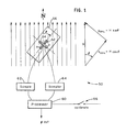
- the arrangement 50 of the two coils 52, 54 is shown in Fig. 1.
- the x coil 52 is parallel to the compass housing 56 so that when the compass is pointed north, the x coil 52 reads the magnitude of the horizontal magnetic field (H) and the y coil reads zero.
- the coil cruciform is symmetrical and fixed with respect to the compass case and contains no moving parts. It may be gimballed to provide a horizontal reference, or strapped down.
- the output signals from the coils 52 and 54 are sampled by respective signal samples 62 and 64 which provide a signal to the processor 60 for calculation of the bearing angle and to provide error correction. The errors are corrected during a calibration process, described below, when a calibration switch 66 enables the process.
- the samples 62 and 64 and the processor 60 may be analog, digital, or a combination thereof.
- Any misalignment of the longitudinal axis of the x coil 52 and the lubber line 58 of the compass case 56 causes a bias error in the solid state compass that is identical to that of the optical compass, so that the compass output bearing is where a is the alignment error and 6 is the actual compass bearing.
- Any permanent magnetic material attached to the compass case may be modelled as a bias term in each of the coil outputs.
- a permanent magnet with field strength Hp that is oriented so that the angle between the x coil axis and the axis of the permanent magnet is y.
- the coil outputs are Note that the values of Hp cosY and Hp sin Y are constant because the permanent magnet is fixed with respect to the x and y coils and rotates with the compass case.
- the coil outputs may be expressed in general as: where Px and Py are the summed effects of permanent magnetism on the x coil and the y coil respectively. Therefore, any permanent magnetic material (not shown) with the compass or in the vehicle within which the compass is mounted creates a fixed DC level shift (bias) in each of the coil outputs.
- the solid state compass output is similar to that of the optical units.
- the errors may be corrected by removing the x and y coil bias prior to calculating the compass output azimuth ⁇ .
- the bias removal is the preferable means of calibration, since the bias correction is latitude independent.
- any soft iron or permeable material will have some field induced within it by the presence of the earth's field.
- the soft iron effect may be modelled by a bar of permeable material (not shown) oriented so that the angle from the x coil axis to the bar axis is Y .
- the magnitude of the field induced by the earth's field is a function of earth's field strength (H) and compass orientation (8): where Hs is the induced field strength, l, is the ratio of induced field strength to earth's field strength when the bar is aligned with the earth's field, 8 is the actual compass bearing, and y is the angle measured from the longitudinal axis of the x coil to the longitudinal axis of the permeable material.
- phase shift errors may be modelled as an A-type error and an E-type error.
- the soft iron errors may be corrected by removing the gain mismatch and phase error between the coils.
- the removal of gain mismatch and phase error is the preferable means of calibration, since they are latitude independent corrections.
- the coil bias values may be measured by: 1) averaging data that is sampled at regular intervals around the compass, or by 2) identifying the minimum and maximum values for each coil and calculating the center value, or by 3) placing the compass in a mu-metal container and measuring the output in the absence of a magnetic field.
- the second method is the simplest, i.e., to turn the compass through 360°, identify the minimum and the maximum points, and calculate the bias.
- the coil gain mismatch may be measured by 1) averaging the squares of data that is sampled at regular intervals around the compass, or by 2) identifying the minimum and maximum values for each coil and forming a ratio, or by 3) inducing a known field in each coil, measuring its value, and forming a ratio. Again, for field calibration, use the second method.
- the phase error between coils may be calculated from any ordered pair of x coil and y coil outputs, so that any data collected for steps 1 and 2 may be used in step 3.
- the preferred method is to select the phase error that minimizes the orthogonality errors between the pairs of coil outputs in the least-squares sense. The phase error may then be used to adjust the phase of the y coil output.
- any of the above calibration coefficients may be calculated using data collected during one or more compass revolution.
- the x coil absolute reference may be found by ensuring that the x coil reading is zero when placed at right angles to the lines of flux of the earth's magnetic field.
- the gimbals must be balanced so that the solid state coils do not pick up any components of the vertical field, or the vertical field.may be measured by a third coil and the output signal may be used to remove the effect of vertical field bias in each coil output signal. If the gimbals are not properly balanced (with x,y coils horizontal) and the coil output signals are not corrected for the vertical field adjustment, the calibration procedure is still valid but only for the magnetic latitude where the calibration was conducted.
- the calibration procedure may be alternately performed in part in the laboratory, wherein the following equations are computed:
- the next step is completed by measuring the difference between known headings and compass output headings.
- the result at any heading should be a fixed A, which is subtracted from the heading output as the final correction step. or
- a calibration method has been developed to provide a simple procedure for field calibrating solid state compasses.
- the calibration technique requires only a slow rotation of the compass through at least 360° and a digital computer for parameter calculations.
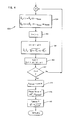
- the process according to the present invention and implemented in the processor 60, described above, includes the process 100 steps illustrated by the flowchart comprising Figs. 2-4.
- the process 100 is initialized at step 102, wherein the data point index I and other parameters are initialized and the coil values are read from the samplers at step 104.
- the signals read are processed to provide an angle from an arc tangent, which is also stored in step 106, which then issues instructions to indicate that the calibration turn may be begun at step 108.
- the signals from the orthogonal sensing coils are read at step 110, and smoothed angle estimates are provided at step 112.
- the step 114 provides the minimum/maximum routine after which a new value of angle is calculated at step 116 from the arctangent of the estimated signal values.
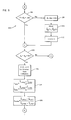
- the process 100 continues on Fig. 3, wherein the relative magnitude of the angles 8 and e R is determined at step 118 relative to an incremental value, initially 1°. If the value of the angle is less than the reference angle ⁇ R plus the increment, the difference between the reference and the measured angle is compared to 370° at step 120. If the magnitude is greater than 370°, the value K (maximum sample index number) is set to the value of index I, and index I is reset to zero, indicating that the calibration data is complete at step 122. Thereafter, the X and Y bias coefficients are determined at step 124 as well as determining the Y scale coefficient at step 126.
- step 118 If in step 118 the angle is not less than the reference angle plus an incremental value, the system begins step 128, calculating a ⁇ K , and storing a value at step 130, thereafter incrementing the index I by 1 at step 132 to resume the process beginning with step 120, discussed above. If the angle difference measured in step 120 is not greater than 370°, the system then jumps to step 110, to thereafter repeat the above-described sequence.
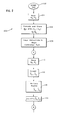
- the process 100 continues on Fig. 4, wherein the corrected signals are calculated at step 134. Afterwards, the I parameter is incremented by 1 at step 136. The sin value is calculated at step 138, whereafter the step 140 provides a sum of the calculated signals. At step 142, the index I is compared to the maximum data point index K, and if equal, the process continues at step 144, wherein the Sp hase parameter is calculated. The phase error is thereafter calculated at step 146, and finally the C phase value is calculated at step 148. Afterwards, the initialization and calibration program returns, and the compass may now produce precise angle readings according to the method according to the present invention.
Applications Claiming Priority (2)
| Application Number | Priority Date | Filing Date | Title |
|---|---|---|---|
| US807523 | 1985-12-11 | ||
| US06/807,523 US4698912A (en) | 1985-12-11 | 1985-12-11 | Magnetic compass calibration |
Publications (3)
| Publication Number | Publication Date |
|---|---|
| EP0225493A2 true EP0225493A2 (fr) | 1987-06-16 |
| EP0225493A3 EP0225493A3 (en) | 1989-05-03 |
| EP0225493B1 EP0225493B1 (fr) | 1992-07-22 |
Family
ID=25196576
Family Applications (1)
| Application Number | Title | Priority Date | Filing Date |
|---|---|---|---|
| EP86115559A Expired - Lifetime EP0225493B1 (fr) | 1985-12-11 | 1986-11-10 | Calibrage d'un compas magnétique |
Country Status (5)
| Country | Link |
|---|---|
| US (1) | US4698912A (fr) |
| EP (1) | EP0225493B1 (fr) |
| JP (1) | JP2549283B2 (fr) |
| CA (1) | CA1270635A (fr) |
| DE (1) | DE3686138T2 (fr) |
Cited By (2)
| Publication number | Priority date | Publication date | Assignee | Title |
|---|---|---|---|---|
| US8843338B2 (en) | 2011-07-29 | 2014-09-23 | Nokia Corporation | Processing Data for Calibration |
| DE102021210552A1 (de) | 2021-09-22 | 2023-03-23 | Fraunhofer-Gesellschaft zur Förderung der angewandten Forschung eingetragener Verein | Vorrichtung und verfahren zum kalibrieren eines magnetsensorsystems mittels einer inhomogenen magnetfeldquelle |
Families Citing this family (42)
| Publication number | Priority date | Publication date | Assignee | Title |
|---|---|---|---|---|
| DE3682730D1 (de) * | 1985-09-03 | 1992-01-16 | British Aerospace | Eichung eines magnetischen kompasses. |
| US4750349A (en) * | 1985-12-27 | 1988-06-14 | Chrysler Motors Corporation | Microcomputer controlled quick ranging technique and digital filter |
| DE3644681A1 (de) * | 1986-12-30 | 1988-07-14 | Bosch Gmbh Robert | Navigationsverfahren fuer fahrzeuge mit elektronischem kompass |
| JPH01214710A (ja) * | 1988-02-23 | 1989-08-29 | Alps Electric Co Ltd | 方位計測方法およびその装置 |
| US5010653A (en) * | 1988-02-29 | 1991-04-30 | Digicourse, Inc. | Apparatus and method for determining azimuth, pitch and roll |
| US4843865A (en) * | 1988-02-29 | 1989-07-04 | Digicourse, Inc. | Method of calibrating a compass heading |
| US5105548A (en) * | 1988-02-29 | 1992-04-21 | Digicourse, Inc. | Apparatus and method for determining azimuth, pitch and roll |
| US5333110A (en) * | 1991-12-27 | 1994-07-26 | Chrysler Corporation | Electronic magnetic compass system and method for interpreting directions of a vehicle |
| US5351204A (en) * | 1991-12-27 | 1994-09-27 | Chrysler Corporation | Scaling system and method for an electronic compass |
| US5323336A (en) * | 1991-12-27 | 1994-06-21 | Chrysler Corporation | Noise removal method for an electronic compass |
| US5253424A (en) * | 1991-12-27 | 1993-10-19 | Chrysler Corporation | Flux-gate sensor mounting and method |
| US5297063A (en) * | 1991-12-27 | 1994-03-22 | Chrysler Corporation | Method for selecting calibration data for an auto-calibrating compass |
| US5828984A (en) * | 1991-12-27 | 1998-10-27 | Chrysler Corporation | Data processing method for an electronic compass system |
| US5297065A (en) * | 1991-12-27 | 1994-03-22 | Chrysler Corporation | Magnetic transient detection and calibration technique for an auto-calibrating compass |
| US5353241A (en) * | 1991-12-27 | 1994-10-04 | Al Attar Rafi A | Shifting system and method for an electronic compass system |
| US5187872A (en) * | 1992-04-02 | 1993-02-23 | Her Majesty The Queen In Right Of Canada, As Represented By The Minister Of Communications | Automatic calibration of magnetic compasses |
| US5737226A (en) * | 1995-06-05 | 1998-04-07 | Prince Corporation | Vehicle compass system with automatic calibration |
| US5878370A (en) * | 1995-12-01 | 1999-03-02 | Prince Corporation | Vehicle compass system with variable resolution |
| DE19609762C1 (de) * | 1996-03-13 | 1997-04-03 | Leica Ag | Verfahren zur Bestimmung der Richtung des Erdmagnetfeldes |
| US6513252B1 (en) * | 1999-04-08 | 2003-02-04 | Donnelly Corporation | Vehicle compass compensation |
| US6301794B1 (en) * | 1999-05-27 | 2001-10-16 | Johnson Controls, Inc. | Vehicle compass system with continuous automatic calibration |
| US6577976B1 (en) | 1999-09-17 | 2003-06-10 | Hrl Laboratories, Llc | Method for dynamic autocalibration of a multi-sensor tracking system and apparatus incorporating it therein |
| US6543146B2 (en) * | 2000-12-06 | 2003-04-08 | Honeywell International, Inc. | Electronic compass and compensation of large magnetic errors for operation over all orientations |
| JP4244561B2 (ja) * | 2001-07-10 | 2009-03-25 | ヤマハ株式会社 | 方位測定機能を有する携帯型電子装置 |
| US6836971B1 (en) * | 2003-07-30 | 2005-01-04 | Honeywell International Inc. | System for using a 2-axis magnetic sensor for a 3-axis compass solution |
| KR100561849B1 (ko) | 2003-11-13 | 2006-03-16 | 삼성전자주식회사 | 이동체의 방위각 보정방법 및 장치 |
| KR100612836B1 (ko) * | 2003-12-13 | 2006-08-18 | 삼성전자주식회사 | 자장 이용 방법 및 장치 |
| KR100565794B1 (ko) * | 2003-12-30 | 2006-03-29 | 삼성전자주식회사 | 기울기의 영향을 보상하여 방위각을 연산하는 지자기센서, 및 그 연산방법 |
| KR100574506B1 (ko) * | 2004-02-26 | 2006-04-27 | 삼성전자주식회사 | 연산된 방위각의 오류여부를 표시하는 지자기센서 및 그방위각측정방법 |
| US6877237B1 (en) * | 2004-03-05 | 2005-04-12 | Honeywell International Inc. | Method and system for acquiring calibration data for an electronic compass |
| JP4639672B2 (ja) * | 2004-07-12 | 2011-02-23 | ヤマハ株式会社 | 地磁気センサの補正方法 |
| JP4586172B2 (ja) * | 2005-12-07 | 2010-11-24 | 独立行政法人海洋研究開発機構 | 慣性航法システム |
| KR20080026395A (ko) * | 2006-09-20 | 2008-03-25 | 삼성전자주식회사 | 자기 환경을 고려한 컴퍼스 센서의 교정 방법 및 장치와이를 이용한 방위각 측정 방법 및 장치 |
| US8108171B2 (en) * | 2009-09-14 | 2012-01-31 | Honeywell International, Inc. | Systems and methods for calibration of gyroscopes and a magnetic compass |
| US8548766B2 (en) | 2009-09-14 | 2013-10-01 | Honeywell International Inc. | Systems and methods for gyroscope calibration |
| US8577637B2 (en) * | 2009-09-28 | 2013-11-05 | Teledyne Rd Instruments, Inc. | System and method of magnetic compass calibration |
| US8374816B2 (en) * | 2010-06-08 | 2013-02-12 | Honeywell International Inc. | Automatic data collection algorithm for 3D magnetic field calibration with reduced memory requirements |
| US8931326B1 (en) | 2010-07-02 | 2015-01-13 | Tiax Llc | Strapdown heading sensors and systems, and methods of calibrating and compensating the same |
| US8463569B2 (en) | 2011-03-21 | 2013-06-11 | Caterpillar Trimble Control Technologies Llc | Method of operating a magnetic compass on a machine |
| US11959751B2 (en) * | 2016-05-26 | 2024-04-16 | Apple Inc. | Correcting compass view using map data |
| CN109328325B (zh) * | 2017-12-18 | 2021-10-22 | 深圳市大疆灵眸科技有限公司 | 云台控制方法、可移动物体、存储装置、云台控制系统和云台 |
| CN111505538B (zh) * | 2020-03-17 | 2022-12-09 | 天津中科华誉科技有限公司 | 磁场方向传感器校正和计算方法、装置、存储介质及设备 |
Citations (6)
| Publication number | Priority date | Publication date | Assignee | Title |
|---|---|---|---|---|
| FR2302505A1 (fr) * | 1975-02-26 | 1976-09-24 | Sagem | Procede et dispositif pour la compensation d'une vanne de flux |
| US4031630A (en) * | 1976-06-17 | 1977-06-28 | The Laitram Corporation | Calibration apparatus for automatic magnetic compass correction |
| EP0041892A1 (fr) * | 1980-06-05 | 1981-12-16 | Crouzet | Procédés de compensation des perturbations magnétiques dans la détermination d'un cap magnétique, et dispositifs pour la mise en oeuvre de ces procédés |
| EP0067338A2 (fr) * | 1981-06-11 | 1982-12-22 | Siemens Aktiengesellschaft | Méthode de correction pour une sonde de champ magnétique |
| US4445279A (en) * | 1981-08-13 | 1984-05-01 | Alps Electric Co., Ltd. | Magnetic course detector |
| GB2128749A (en) * | 1982-10-12 | 1984-05-02 | Plessey Co Plc | Electronic compass with tilt compensation |
Family Cites Families (9)
| Publication number | Priority date | Publication date | Assignee | Title |
|---|---|---|---|---|
| US3938257A (en) * | 1974-12-02 | 1976-02-17 | Sperry Rand Corporation | Two-cycle compensator for flux valve heading repeater system |
| US3991361A (en) * | 1975-03-27 | 1976-11-09 | Westinghouse Electric Corporation | Semi-automatic compass calibrator apparatus for a vehicle mounted flux gate compass system to cancel out effect of local magnetic disturbances |
| US4262427A (en) * | 1979-08-10 | 1981-04-21 | Sperry Corporation | Flux valve compass system |
| JPS6212976Y2 (fr) * | 1980-10-20 | 1987-04-03 | ||
| JPS5776411A (en) * | 1980-10-29 | 1982-05-13 | Toyota Motor Corp | Method and apparatus for correcting output of azimuth detector |
| JPS5822911A (ja) * | 1981-08-04 | 1983-02-10 | Nippon Soken Inc | 方位検出装置 |
| JPS5826213A (ja) * | 1981-08-08 | 1983-02-16 | Nippon Soken Inc | 方位検出装置 |
| JPS5991311A (ja) * | 1982-10-12 | 1984-05-26 | ロケ マナ リサーチ リミテッド | 電子コンパスを有する乗物ナビゲーション装置 |
| JPS5985910A (ja) * | 1982-11-09 | 1984-05-18 | Nippon Telegr & Teleph Corp <Ntt> | 磁界ベクトル検出方式 |
-
1985
- 1985-12-11 US US06/807,523 patent/US4698912A/en not_active Expired - Lifetime
-
1986
- 1986-11-06 CA CA000522394A patent/CA1270635A/fr not_active Expired
- 1986-11-10 EP EP86115559A patent/EP0225493B1/fr not_active Expired - Lifetime
- 1986-11-10 DE DE8686115559T patent/DE3686138T2/de not_active Expired - Fee Related
- 1986-12-11 JP JP61295691A patent/JP2549283B2/ja not_active Expired - Fee Related
Patent Citations (6)
| Publication number | Priority date | Publication date | Assignee | Title |
|---|---|---|---|---|
| FR2302505A1 (fr) * | 1975-02-26 | 1976-09-24 | Sagem | Procede et dispositif pour la compensation d'une vanne de flux |
| US4031630A (en) * | 1976-06-17 | 1977-06-28 | The Laitram Corporation | Calibration apparatus for automatic magnetic compass correction |
| EP0041892A1 (fr) * | 1980-06-05 | 1981-12-16 | Crouzet | Procédés de compensation des perturbations magnétiques dans la détermination d'un cap magnétique, et dispositifs pour la mise en oeuvre de ces procédés |
| EP0067338A2 (fr) * | 1981-06-11 | 1982-12-22 | Siemens Aktiengesellschaft | Méthode de correction pour une sonde de champ magnétique |
| US4445279A (en) * | 1981-08-13 | 1984-05-01 | Alps Electric Co., Ltd. | Magnetic course detector |
| GB2128749A (en) * | 1982-10-12 | 1984-05-02 | Plessey Co Plc | Electronic compass with tilt compensation |
Cited By (3)
| Publication number | Priority date | Publication date | Assignee | Title |
|---|---|---|---|---|
| US8843338B2 (en) | 2011-07-29 | 2014-09-23 | Nokia Corporation | Processing Data for Calibration |
| DE102021210552A1 (de) | 2021-09-22 | 2023-03-23 | Fraunhofer-Gesellschaft zur Förderung der angewandten Forschung eingetragener Verein | Vorrichtung und verfahren zum kalibrieren eines magnetsensorsystems mittels einer inhomogenen magnetfeldquelle |
| DE102021210552B4 (de) | 2021-09-22 | 2023-05-17 | Fraunhofer-Gesellschaft zur Förderung der angewandten Forschung eingetragener Verein | Vorrichtung und verfahren zum kalibrieren eines magnetsensorsystems mittels einer inhomogenen magnetfeldquelle |
Also Published As
| Publication number | Publication date |
|---|---|
| CA1270635A (fr) | 1990-06-26 |
| DE3686138D1 (de) | 1992-08-27 |
| EP0225493B1 (fr) | 1992-07-22 |
| EP0225493A3 (en) | 1989-05-03 |
| JP2549283B2 (ja) | 1996-10-30 |
| JPS62140015A (ja) | 1987-06-23 |
| US4698912A (en) | 1987-10-13 |
| DE3686138T2 (de) | 1993-01-14 |
Similar Documents
| Publication | Publication Date | Title |
|---|---|---|
| US4698912A (en) | Magnetic compass calibration | |
| US4414753A (en) | Process for compensating the magnetic disturbances in the determination of a magnetic heading, and devices for carrying out this process | |
| CA1295126C (fr) | Magnetometre insensible au roulis | |
| US7555398B2 (en) | Sensor system error reduction | |
| US3991361A (en) | Semi-automatic compass calibrator apparatus for a vehicle mounted flux gate compass system to cancel out effect of local magnetic disturbances | |
| CA2431722C (fr) | Compas electronique et correction d'erreurs magnetiques importantes pour un fonctionnement selon toutes les orientations | |
| Isezaki | A new shipboard three-component magnetometer | |
| US4686772A (en) | Electronic magnetic compass system | |
| US4870602A (en) | Method for determining route angles | |
| CN102252689A (zh) | 一种基于磁传感器的电子罗盘校准方法 | |
| JP2007500350A (ja) | 3軸コンパスソリューションのための2軸磁気センサを使用するシステム | |
| NO323891B1 (no) | Fremgangsmate for bestemmelse av jordmagnetfeltets retning | |
| CN107024673B (zh) | 基于陀螺仪辅助的三轴磁强计全误差标定方法 | |
| Markovič et al. | Calibration of a solid-state magnetic compass using angular-rate information from low-cost sensors | |
| GB2128749A (en) | Electronic compass with tilt compensation | |
| KR100550944B1 (ko) | 수정파라미터의결정방법 | |
| US5425178A (en) | Solar compass | |
| CN108803373B (zh) | 一种三轴转台的地速消除方法 | |
| US5065521A (en) | Magnetic field measurement and compass calibration in areas of magnetic disturbance | |
| CN110702102B (zh) | 一种用于通航飞机的磁导航系统及其导航方法 | |
| Hemshorn et al. | DI-flux measurement of the geomagnetic field using a three-axial fluxgate sensor | |
| Auster et al. | A new method for performing an absolute measurement of the geomagnetic field | |
| JP2609976B2 (ja) | 方位計 | |
| US11333498B2 (en) | Magnetic compass compensation | |
| Marsal et al. | An evaluation of the uncertainty associated with the measurement of the geomagnetic field with a D/I fluxgate theodolite |
Legal Events
| Date | Code | Title | Description |
|---|---|---|---|
| PUAI | Public reference made under article 153(3) epc to a published international application that has entered the european phase |
Free format text: ORIGINAL CODE: 0009012 |
|
| AK | Designated contracting states |
Kind code of ref document: A2 Designated state(s): DE FR GB IT |
|
| PUAL | Search report despatched |
Free format text: ORIGINAL CODE: 0009013 |
|
| AK | Designated contracting states |
Kind code of ref document: A3 Designated state(s): DE FR GB IT |
|
| 17P | Request for examination filed |
Effective date: 19890913 |
|
| 17Q | First examination report despatched |
Effective date: 19900910 |
|
| ITTA | It: last paid annual fee | ||
| GRAA | (expected) grant |
Free format text: ORIGINAL CODE: 0009210 |
|
| AK | Designated contracting states |
Kind code of ref document: B1 Designated state(s): DE FR GB IT |
|
| REF | Corresponds to: |
Ref document number: 3686138 Country of ref document: DE Date of ref document: 19920827 |
|
| ET | Fr: translation filed | ||
| ITF | It: translation for a ep patent filed |
Owner name: GUZZI E RAVIZZA S.R.L. |
|
| PLBE | No opposition filed within time limit |
Free format text: ORIGINAL CODE: 0009261 |
|
| STAA | Information on the status of an ep patent application or granted ep patent |
Free format text: STATUS: NO OPPOSITION FILED WITHIN TIME LIMIT |
|
| 26N | No opposition filed | ||
| REG | Reference to a national code |
Ref country code: GB Ref legal event code: 732E |
|
| REG | Reference to a national code |
Ref country code: FR Ref legal event code: TP |
|
| REG | Reference to a national code |
Ref country code: GB Ref legal event code: IF02 |
|
| PGFP | Annual fee paid to national office [announced via postgrant information from national office to epo] |
Ref country code: DE Payment date: 20021127 Year of fee payment: 17 |
|
| PG25 | Lapsed in a contracting state [announced via postgrant information from national office to epo] |
Ref country code: DE Free format text: LAPSE BECAUSE OF NON-PAYMENT OF DUE FEES Effective date: 20040602 |
|
| PGFP | Annual fee paid to national office [announced via postgrant information from national office to epo] |
Ref country code: GB Payment date: 20051004 Year of fee payment: 20 |
|
| PGFP | Annual fee paid to national office [announced via postgrant information from national office to epo] |
Ref country code: FR Payment date: 20051104 Year of fee payment: 20 |
|
| PG25 | Lapsed in a contracting state [announced via postgrant information from national office to epo] |
Ref country code: IT Free format text: LAPSE BECAUSE OF NON-PAYMENT OF DUE FEES;WARNING: LAPSES OF ITALIAN PATENTS WITH EFFECTIVE DATE BEFORE 2007 MAY HAVE OCCURRED AT ANY TIME BEFORE 2007. THE CORRECT EFFECTIVE DATE MAY BE DIFFERENT FROM THE ONE RECORDED. Effective date: 20051110 |
|
| PG25 | Lapsed in a contracting state [announced via postgrant information from national office to epo] |
Ref country code: GB Free format text: LAPSE BECAUSE OF EXPIRATION OF PROTECTION Effective date: 20061109 |
|
| REG | Reference to a national code |
Ref country code: GB Ref legal event code: PE20 |