EP0225416A1 - Pneumatische, diskontinuierlich arbeitende Einrichtung zum Pumpen von geladenen Flüssigkeiten - Google Patents
Pneumatische, diskontinuierlich arbeitende Einrichtung zum Pumpen von geladenen Flüssigkeiten Download PDFInfo
- Publication number
- EP0225416A1 EP0225416A1 EP85402197A EP85402197A EP0225416A1 EP 0225416 A1 EP0225416 A1 EP 0225416A1 EP 85402197 A EP85402197 A EP 85402197A EP 85402197 A EP85402197 A EP 85402197A EP 0225416 A1 EP0225416 A1 EP 0225416A1
- Authority
- EP
- European Patent Office
- Prior art keywords
- valve
- orifice
- downstream
- pumping chamber
- pipe
- Prior art date
- Legal status (The legal status is an assumption and is not a legal conclusion. Google has not performed a legal analysis and makes no representation as to the accuracy of the status listed.)
- Granted
Links
Images

Classifications
-
- F—MECHANICAL ENGINEERING; LIGHTING; HEATING; WEAPONS; BLASTING
- F04—POSITIVE - DISPLACEMENT MACHINES FOR LIQUIDS; PUMPS FOR LIQUIDS OR ELASTIC FLUIDS
- F04F—PUMPING OF FLUID BY DIRECT CONTACT OF ANOTHER FLUID OR BY USING INERTIA OF FLUID TO BE PUMPED; SIPHONS
- F04F1/00—Pumps using positively or negatively pressurised fluid medium acting directly on the liquid to be pumped
- F04F1/06—Pumps using positively or negatively pressurised fluid medium acting directly on the liquid to be pumped the fluid medium acting on the surface of the liquid to be pumped
- F04F1/14—Pumps using positively or negatively pressurised fluid medium acting directly on the liquid to be pumped the fluid medium acting on the surface of the liquid to be pumped adapted to pump specific liquids, e.g. corrosive or hot liquids
Definitions
- the present invention relates to a pneumatic device, operating discontinuously, for pumping charged liquids.
- the invention more particularly relates to a pumping device, operating discontinuously and with compressed air, and making it possible to convey charged liquids, possibly viscous, abrasive or corrosive, such as pulp or sludge of high density having significant abrasion power.
- sludge pumps all include at least one piston or at least one member driven in rotation by an electric motor.
- a lubrication installation is generally provided to reduce the friction of the mobile member (s) which generate significant overheating.
- the moving parts of these pumps wear out very quickly, due to abrasion phenomena.
- a pneumatic device for supplying bulk materials comprising two identical supply containers articulated in a pendulum arrangement at the two ends of an oscillating beam, so that the containers are moved, alternately and in opposition, from a high position, in which they are filled with a material to be conveyed, to a low position, in which the load of materials is discharged from the containers.
- Each container comprises a tubular body inside which a filter cartridge, retaining the dust and allowing the air to pass, delimits a longitudinal chamber in the upstream and downstream ends of which respectively open an inlet orifice and an outlet orifice, which can be closed off respectively by an inlet flap valve and an outlet flap valve.
- two lateral pipes one of which, upstream, is a suction pipe connected by a valve to a source of vacuum, and the other of which, downstream, is a pressurization pipe connected by another valve to a source of compressed air, open into the annular chamber delimited between the filter cartridge and the tubular body of the container.
- the inlet valve opens and the longitudinal chamber in the filter cartridge is filled, by suction, with bulk material which is brought to the inlet via a flexible pipe.
- the filter cartridge isolates the suction pipe from the materials sucked into the chamber internal to the cartridge.
- the corresponding container descends to the low position and the connection between the suction pipe and the vacuum source is cut.
- the connection between the pressurization tubing and the source of compressed air is established, and pressurized air is thus injected into the tubular body.
- the inlet valve is closed and the outlet valve is open, and the material charge contained in the chamber internal to the filter cartridge is driven out of the tubular body by the outlet orifice and discharged by a flexible evacuation pipe.
- this device due to the sequence of operation in sequence, like an airlock, which requires filling by suction and emptying by pressurization, this device must include two swing valves necessary to delimit the chamber of the airlock, and the discharge line , downstream of the outlet valve, is never completely emptied.
- this device is designed to convey bulk products, but in no case loaded liquids or sludge, because it comprises an essential element for its operation, namely the filter cartridge, isolating the pipes from suction and pressurization of the conveyed materials and which would very quickly be clogged by sludge or other charges in the transported liquids, after several operating cycles.
- another object of the invention is to propose a pumping device charged liquids which are, by design, explosion-proof (without electric motor), perfectly watertight (without cable gland or seal), with constant performance (without organ such as a membrane whose mechanical characteristics degrade in time), and low energy consumption.
- Yet another object of the invention is to provide a pumping device for charged liquids which is compact, easy to transport and install, and very economical to purchase and maintain.
- Yet another object of the invention is to provide a pumping device resistant to abrasion, capable of conveying heterogeneous sludge containing solids whose size can be relatively large, and which is submersible.
- a pneumatic pumping device for charged liquids, operating discontinuously, and intended to be constantly under load, either by immersion in a tank of charged liquids, or by connection to this tank by a pipe, and including: - A tubular body delimiting an internal chamber in the upstream and downstream ends of which respectively open an inlet orifice and an outlet orifice; - At least one injection pipe for compressed gases, such as air, opening into the internal chamber through at least one pressurization orifice; - a supply valve connected to each injection pipe and intended to be connected a source of compressed gas to ensure a selective supply of each injection pipe with compressed gas and; - a control member of the supply valve; and this device according to the invention is characterized in that it further comprises a single flap valve, mounted on a fixed support inside the internal chamber, between the inlet port and the pressurization orifice, and cooperating with a seat internal to the body, surrounding an orifice for the passage of the charged liquid, and delimiting, between it and the outlet orific
- the pumping device according to the invention is therefore of a very simple structure, since it comprises only one moving part, which is a flapper valve of an easy realization. In addition, it ensures total evacuation of the volume of charged liquid contained in the pumping chamber and in a discharge pipe which is connected to the body, at the outlet orifice, in order to transport any charged liquid. , dense and / or viscous, or a mud, up to the open air or in a container put in the open air. In addition, the device according to the invention is of a structure such that after an operation stop, it can be put back into operation without fear of clogging of the tubular body or of the discharge pipe.
- the tubular body is constituted by the end-to-end mounting of two cylindrical ferrules (or sections of tube), assembled by the joining of two flanges of their adjacent ends, between which is held the valve support , in which the passage orifice is formed, the periphery of which, on the side of the outlet orifice, forms the seat of the valve, a single compressed gas injection pipe opening out through a single pressurization orifice in the upper part of the pumping chamber, delimited in the downstream ferrule (or section of tube).
- ferrules or sections of tube which each have, at each of its two axial ends, a securing flange, the upstream flange of the upstream ferrule and the downstream flange the downstream shell being intended for example, for the connection of the tubular body respectively to a supply pipe for the pumping device with loaded liquids and to a delivery pipe for the loaded liquid, outside of the device.
- the pumping chamber is delimited in the body tubular consisting of an upstream part in the form of a cylindrical shell, in which a single injection pipe opens out by a single pressurization orifice, and which extends downstream by a convergent substantially in the form of a truncated cone offset towards the low.
- the upstream end of the cylindrical shell of the body has a flange for securing to a flange of the downstream end of a filling tube which opens into the cylindrical shell by delimiting the inlet opening in the body, and the flapper valve is supported by the downstream flange of the filling pipe, while the downstream end of the convergent is extended downstream by a delivery pipe having means for connection to a delivery pipe.
- the orifice for venting the pumping chamber necessary to facilitate filling of the latter, can be simply delimited by the downstream end of the line of repression.
- the compressed gas supply valve can then be a simple two-way valve.
- the compressed gas supply valve be a three-way valve. channels, one channel of which allows the pumping chamber to be vented through the injection manifold, the outlet orifice at the downstream end of the delivery pipe still being able to act as emergency vent hole, in the event of valve failure.
- the flapper valve can be either of a type which is pivotally mounted as a whole about a fixed axis on the support and perpendicular to the direction of flow of the liquids loaded into the tubular body, or of a type comprising a shutter mobile, intended to be applied in a sealed manner against the valve seat, a flap for fixing to the support, and a flexible part, which connects the shutter to the flap and which forms a hinge allowing the pivoting of the shutter relative to the bib.
- the flapper valve may include a rigid core, for example metallic, which is glued to or embedded in a plate of rubber material, allowing quieter operation of the device and ensuring better sealing by pressing against the seat valve.
- the device comprises flanges for fixing the constituent elements of the tubing body to each other, and / or to filling and / or delivery pipes and / or pipes
- the flanges have several recesses opening in their periphery and intended to be arranged opposite each other on two adjacent flanges to be joined in order to receive, by pivoting, the threaded rods, on which are screwed nuts, of eye bolts mounted each pivoting by its eye about a carried axis by a yoke projecting outwards on the constituent element of the body, the tubing or the pipe which has one of the two adjacent flanges to be joined, and so that the corresponding nut can be tightened against the other flange adjacent to join.
- control member of the compressed gas supply valve advantageously comprises a timer triggering the filling and emptying cycles of the pumping chamber.
- non-return valves each of which is preferably of the type swing valve with or without compressed gas injection pipe opening through a pressurization orifice just downstream of each swing valve, which makes it possible to evacuate the liquids charged by a discharge column subdivided into consecutive segments, delimited between two check valves - successive returns, and by achieving significant savings in compressed gas injected into the entire device to ensure pumping over a large distance, possibly up to a reception point for charged liquids and expansion of the compressed gas, and which is realized as a cyclone of relaxation.
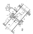
- the device shown in FIG. 1 comprises a tubular body 1, constituted by the end-to-end and coaxial assembly of two cylindrical ferrules 2 and 2 ', substantially identical but arranged symmetrically with respect to the transverse connection plane.
- Each ferrule 2 or 2 ' is in one piece, at one of its two axial ends, with an external radial peripheral flange 3, in the form of a beaten collar, while another radial and external peripheral flange 4, in annular crown shape, has been added by welding on its other axial end.
- the downstream flange of the upstream ferrule 2 and the upstream flange of the downstream ferrule 2' are the two flanges in beaten collars 3 arranged facing one of the other, while the upstream flange of the upstream ferrule 2 and the downstream flange of the downstream ferrule 2 'are the flanges in added crown 4.
- the flanges 3 and 4 are, in the usual manner, drilled in the axial direction, with holes such that 5, for the passage of bolts such as 6 on which are screwed nuts such as 7, tightened against the flanges to ensure their attachment to each other or to other members.
- a flapper valve 12 is pivotally mounted in one piece on the downstream face of the support 8.
- This valve 12 has, for example, the shape of a disc of larger diameter than the circular orifice 11, and the upper part of which is integral with a sleeve 13 by which the valve 12 is mounted journalling about a horizontal and transverse axis 14, carried by a yoke projecting from the downstream face of the support 8.
- the valve 12 pivots between an open position of the orifice 11 (shown in the position in broken lines in FIG. 1), and in which it is raised downstream, and a position for closing the orifice 11 (represented in solid lines in FIG. 1 ), and in which it is applied, in a sealed manner, against the seat formed on the downstream face of the support 8, on the periphery of the orifice 11.
- This valve 12 is metallic or preferably, with an embedded metallic core in a rubbery material (natural or synthetic rubber, silicone elastomer, etc.).
- the upstream and downstream flanges 5 of the body 1 respectively surround the inlet 15 and the outlet 16 of the internal chamber 10, and the valve 12 pivots in the portion of the chamber 10 which is delimited downstream, between the support 8 and the outlet orifice 16, and which constitutes a pumping chamber 17.
- a pipe 18 for injecting compressed air opens out through a pressurization orifice 19 in the pumping chamber 17, above the level of the lowest point of this chamber 17, at the base of the valve seat, which is itself above the level of the highest point of the chamber 17, in the immediate vicinity of the outlet orifice 16, because the inclination from top to bottom and from upstream to downstream which is given to the body 1.
- the tubing 18 is connected to a channel of a three-way inlet valve 20, of which another channel is connected by tubing 21 to a source of compressed air, and the third channel of which is vented through the nozzle 22.
- the valve 20 is controlled by u n control box 23, comprising in particular an electric, electronic or even pneumatic timer, and controlling the selective communication of the pipe 18, either with the pipe 21 to admit compressed air into the pumping chamber 17, or with the nozzle 22 for venting the pumping chamber 17.
- u n control box 23 comprising in particular an electric, electronic or even pneumatic timer, and controlling the selective communication of the pipe 18, either with the pipe 21 to admit compressed air into the pumping chamber 17, or with the nozzle 22 for venting the pumping chamber 17.
- the flange 4 of its upstream end the body 1 is connected to the downstream end of a filling pipe (not shown) connected to the lower part of a tank for storing a loaded liquid or a decanter or thickener for sludge to be pumped. But it is also possible that by this flange upstream 4, the body 1 is kept immersed on the bottom of such a tank or decanter, so that the device will always be in charge.
- the body 1 is connected to the flange 25 and the upstream end of a discharge pipe 24, the downstream end of which opens directly into the open air, or into a tank 'free air, or in a container for receiving the sludge or loaded liquids and for expanding the compressed air, of the double-walled cyclone type of expansion which avoids splashing of mud or liquid.
- This device operates as follows: at the start of an operating cycle, the box 23 controls the valve 20, so that the tubing 18 and the pumping chamber 17 are brought to the open air by the nozzle 22. As the body 1 is constantly in charge, by the principle of communicating vessels, the charged liquid which enters through the inlet orifice 15 into the chamber 10, pushes the valve 12 back into the open position and fills the pumping chamber 17 , passing through the orifice 11 of the support 8. The box 23 then controls the valve 20, so that the tube 18 is placed in communication with the source of compressed air. Air under an initial pressure of about 0.6 MPa is then injected into the pumping chamber 17.
- the flap valve 12 Under the effect of this pneumatic pressure, the flap valve 12 is pushed against its seat on the support 8, in position closing the passage orifice 11, which isolates the pumping chamber 17 from the reservoir of sludge or charged liquid to be pumped. Simultaneously, the volume of sludge or charged liquid which is present in the pumping chamber 17 and possibly over a certain length in the discharge line 24, is expelled towards outside via the discharge channel 24. If the duration of the compressed air injection is sufficient, the chamber 17 and the discharge line 24 are emptied, then the box 23 again controls the valve 21 to ensure the setting in the open air of the pumping chamber 17 and we find our at the start of the cycle.
- the setting of the timer of the control box 23 makes it possible to adjust the filling and emptying sequences of the device and their frequency.
- This pumping device allows pumping at low flow rate (from 1 at 10 m3 / hour) of loaded liquid and high density mud (from 1.3 to 2.2 or even more) with delivery heights from 10 to 50 m and delivery lengths from 20 to 100 m.
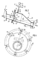
- the device of FIG. 2 which operates in the same manner as that described above with reference to FIG. 1, is essentially distinguished from the latter by the fact that the tubular body 31 consists, in its upstream section, of a cylindrical shell 32 whose downstream end is welded to the upstream end, having the largest cross section, of a convergent 33 constituting the downstream section of the body 31.
- the convergent 33 has substantially the shape of a trunk of cone offset downwards, so that the wall of its lower part is substantially in the extension of the wall of the lower part of the shell 32, parallel to the inclined direction of the body 31, declining from upstream to downstream and from top to bottom, so that the level A of the lowest point in the upstream end of the shell 32 is higher than the level B of the highest point in the downstream end of the converging 33.
- this is obtained when the lower generatrix of the body 31 is inclined by an angle alpha of the order of 15 ° on the horizontal.
- This particular shape of the body 31, made of sheet steel 4 mm thick for example, makes it possible to limit the consumption of compressed air admitted into the body 31 through the pressurization orifice 19, through which the injection tubing 18 opens into the upper part of the ferrule 32, this tubing 18 being connected, as in the previous example, to the 3-way valve 20 controlled by the timer box 23.
- the ferrule 32 At its upstream end, the ferrule 32 has an annular flange 34, projecting radially outwards, attached by welding, and which is fixed by bolting, through or hole 35 to a flange 38 attached by welding around a tube of filling 36, near the downstream end of the latter which opens into the upstream end of the shell 32.
- the filling tube 36 At its upstream end, the filling tube 36 which has substantially the same inclination as the body 31, is integral with a flange 37, substantially vertical, therefore inclined by the angle alpha on a transverse plane perpendicular to the axis of the tube 36.
- the flange 37 makes it possible to fix the bolt by device directly on the outlet of a liquid storage tank loaded to transport or to maintain the device in the submerged position in this tank, or else to connect it to a substantially horizontal loading pipe.
- the downstream end of the pipe 36 delimits the passage orifice 41 which can be closed by the flapper valve 42.
- the seat of the valve is formed by the front face of the downstream end of the pipe 36, and the valve 42 consists, on the one hand, of a rubber plate 43, fixed by bolting its upper part against a boss 39 projecting from the flange 38 towards the inside of the ferrule 32, and intended to close, sealingly, the orifice 41 and on the other hand, a metal disc 44 bonded to the downstream face of the plate 43, in order to stiffen it in the portion of the latter which forms the shutter itself, so that between the covered portion of the metal disc 44 and the portion fixed to the support 39, the rubber plate 43 has a flexible zone forming a hinge, and allowing the pivoting of the shutter part of the valve 42 between, on the one hand, the orifice 41 open position (shown in broken lines in Fig.
- the downstream end of the convergent 33 is connected by welding (or by flange) to the upstream end of a short delivery pipe 48, the downstream end of which 'outlet port 46 of the device and is surrounded by a flange 49 attached by welding.
- This last flange allows the connection of the device to a discharge pipe (not shown).
- check valves can be fitted at regular intervals along the discharge line, for example every 50 m. .
- the discharged column is subdivided into adjacent segments, which are successive and repel each other gradually during the emptying phases of the pumping chamber 47 of the device, during which the check valves are open, the segments adjacent to the pumped column being on the other hand separated by the non-return valves, when the latter are closed, during the filling phases of the pumping chamber 47 of the device.
- flapper devices such as that shown in FIG. 1, without absolutely having to give them the inclination of the device of FIG. 1.
- tubing 18 it is not necessarily necessary in this application to use the tubing 18 for injecting compressed air from the device of FIG. 1.
- An injection of compressed air slightly downstream of each non-return valve is only justified if the total length of the discharge line and / or the system pressure losses are important.
- the venting of the pumping chamber 47 of the device is imperatively ensured, for filling, by the corresponding valve 20.
- valve 42 ′ comprises a circular rubber disc 50, of diameter slightly greater than that of the circular orifice 41, and stiffened by a metal washer 51 forming a core embedded in the disc 50, which thus forms a shutter.
- This disc 50 is extended, at its upper part, by a rectangular rubber flap 52, which has three holes through which it is mounted on the threaded rods of three bolts 53 with head embedded in the parallelepipedic support 39 'welded against the downstream face of the flange 38 ', and the flap 52 is clamped between the support 39' and a pressure plate 54, under the effect of the tightening of the nuts 55 on the bolts 53.
- the portion 56, located between the flap 52 and the disc 50 thus constitutes a flexible zone forming a hinge for pivoting the flap valve 42 '.
- the flanges 34 'and 38' between which a seal 57 is disposed, each have six radial recesses 58, with rounded bottom, which open outwards and are regularly distributed over the periphery.
- a transverse axis 60 extends between the two branches of the yoke 59, and an eye bolt 61 is mounted swiveling by its eye 62 in the yoke 59, around the axis 60.
- An eye nut 64 is further screwed onto the end of the threaded rod 63 of the bolt 61.
- the devices according to the invention have the following advantages: - they constitute volumetric pumping devices; at each cycle, the compressed air drives out a volume of charged liquid or sludge which is equal to the useful sum of the pumping chamber and the discharge pipe (the useful volume of the latter depending only on the charge height and its section). -
- the hourly flow is a function of the number of cycles per hour, controlled by the timer of the control unit 23, and this flow is equal to the number of cycles multiplied by the volume defined above.
- These pumping devices comprise only one moving part, the flapper valve.
- These pumping devices use compressed air as the working fluid; depending on the conditions of use, the air pressure can vary between 0.6 and 0.3 MPa.
- the timer of the box 23 controls the three-way valve 20, the frequencies of venting, the filling time of the pumping chamber and the duration of injection d compressed air, which set the hourly flow rate of the pumping device.
- the causes of failure of this pumping device are limited: they can be a failure of the compressed air supply or a drop in pressure in the supply network, the blocking of a body between the flapper valve and the seat , which does not make it possible to isolate the pumping chamber from the reservoir of liquid loaded to be pumped, but in all cases, disassembly with the device in order to restore it to operating condition, requires only a few minutes.
- the pumping device does not include a motor, cable gland, or lubrication system. - the pumping device is completely sealed (no pollution to fear). - The cost of this pumping device is very interesting compared to those of the "slurry pumps" of the prior art. - The pumping device makes it possible to convey sludge containing hard, abrasive foreign bodies, and other various elements which are not supported by centrifugal or screw pumps. - This pumping device can convey thick sludge of density equal to or greater than 2.2 and containing metal billets. - The maintenance of such a pumping device is simple and inexpensive. - compressed air consumption, although a function of the conditions of use, remains economically attractive.
Landscapes
- Engineering & Computer Science (AREA)
- Mechanical Engineering (AREA)
- General Engineering & Computer Science (AREA)
- Jet Pumps And Other Pumps (AREA)
- Loading And Unloading Of Fuel Tanks Or Ships (AREA)
Priority Applications (6)
| Application Number | Priority Date | Filing Date | Title |
|---|---|---|---|
| FR8407927A FR2564535B1 (fr) | 1984-05-21 | 1984-05-21 | Nouveau dispositif a air comprime fonctionnant en discontinu pour pomper des boues. |
| AT85402197T ATE35803T1 (de) | 1985-11-13 | 1985-11-13 | Pneumatische, diskontinuierlich arbeitende einrichtung zum pumpen von geladenen fluessigkeiten. |
| DE8585402197T DE3563837D1 (en) | 1985-11-13 | 1985-11-13 | Pneumatic discontinually operating apparatus to pump charged liquids |
| US06/797,644 US4684295A (en) | 1985-11-13 | 1985-11-13 | Intermittently operating pneumatic device for pumping solid-carrying liquids and slurries |
| EP85402197A EP0225416B1 (de) | 1985-11-13 | 1985-11-13 | Pneumatische, diskontinuierlich arbeitende Einrichtung zum Pumpen von geladenen Flüssigkeiten |
| US07/247,171 USRE33084E (en) | 1985-11-13 | 1988-09-21 | Intermittently operating pneumatic device for pumping solid-carrying liquids and slurries |
Applications Claiming Priority (1)
| Application Number | Priority Date | Filing Date | Title |
|---|---|---|---|
| EP85402197A EP0225416B1 (de) | 1985-11-13 | 1985-11-13 | Pneumatische, diskontinuierlich arbeitende Einrichtung zum Pumpen von geladenen Flüssigkeiten |
Publications (2)
| Publication Number | Publication Date |
|---|---|
| EP0225416A1 true EP0225416A1 (de) | 1987-06-16 |
| EP0225416B1 EP0225416B1 (de) | 1988-07-20 |
Family
ID=8194550
Family Applications (1)
| Application Number | Title | Priority Date | Filing Date |
|---|---|---|---|
| EP85402197A Expired EP0225416B1 (de) | 1984-05-21 | 1985-11-13 | Pneumatische, diskontinuierlich arbeitende Einrichtung zum Pumpen von geladenen Flüssigkeiten |
Country Status (4)
| Country | Link |
|---|---|
| US (1) | US4684295A (de) |
| EP (1) | EP0225416B1 (de) |
| AT (1) | ATE35803T1 (de) |
| DE (1) | DE3563837D1 (de) |
Cited By (3)
| Publication number | Priority date | Publication date | Assignee | Title |
|---|---|---|---|---|
| USRE33084E (en) * | 1985-11-13 | 1989-10-10 | Intermittently operating pneumatic device for pumping solid-carrying liquids and slurries | |
| GB2266696A (en) * | 1992-05-05 | 1993-11-10 | Brain Ind Limited | Waste receptacle |
| CN105110011A (zh) * | 2015-09-08 | 2015-12-02 | 农业部南京农业机械化研究所 | 一种气力输送用颗粒物料均匀撒铺装置 |
Families Citing this family (2)
| Publication number | Priority date | Publication date | Assignee | Title |
|---|---|---|---|---|
| US5002463A (en) * | 1988-07-29 | 1991-03-26 | Innovac Technology Inc. | Apparatus and method for flow control |
| US5767793A (en) * | 1995-04-21 | 1998-06-16 | Trw Inc. | Compact vehicle based rear and side obstacle detection system including multiple antennae |
Citations (3)
| Publication number | Priority date | Publication date | Assignee | Title |
|---|---|---|---|---|
| DE255849C (de) * | ||||
| FR2406589A1 (fr) * | 1977-10-24 | 1979-05-18 | Clavel Alain | Transporteur de beton a air comprime |
| FR2564535A1 (fr) * | 1984-05-21 | 1985-11-22 | Ranson Jean Francois | Nouveau dispositif a air comprime fonctionnant en discontinu pour pomper des boues. |
Family Cites Families (6)
| Publication number | Priority date | Publication date | Assignee | Title |
|---|---|---|---|---|
| DE503984C (de) * | 1927-11-03 | 1930-07-31 | Franz Schmied | Verfahren zum Befoerdern von Material in groessere Tiefen, insbesondere zum Einbringen von Versatzgut in Gruben, Schaechte usw. mittels Luft |
| US2141920A (en) * | 1937-05-22 | 1938-12-27 | Fuller Co | Conveying apparatus |
| US2299470A (en) * | 1941-06-18 | 1942-10-20 | Fuller Co | Conveying apparatus |
| US4009912A (en) * | 1974-11-04 | 1977-03-01 | Joseph Mraz | Pneumatic conveying apparatus and method |
| US4079746A (en) * | 1975-12-24 | 1978-03-21 | Keystone International, Inc. | Valve assembly having adapter means |
| US4521165A (en) * | 1984-08-31 | 1985-06-04 | Semi-Bulk Systems, Inc. | Apparatus for pumping fluent solid material |
-
1985
- 1985-11-13 DE DE8585402197T patent/DE3563837D1/de not_active Expired
- 1985-11-13 US US06/797,644 patent/US4684295A/en not_active Ceased
- 1985-11-13 EP EP85402197A patent/EP0225416B1/de not_active Expired
- 1985-11-13 AT AT85402197T patent/ATE35803T1/de not_active IP Right Cessation
Patent Citations (3)
| Publication number | Priority date | Publication date | Assignee | Title |
|---|---|---|---|---|
| DE255849C (de) * | ||||
| FR2406589A1 (fr) * | 1977-10-24 | 1979-05-18 | Clavel Alain | Transporteur de beton a air comprime |
| FR2564535A1 (fr) * | 1984-05-21 | 1985-11-22 | Ranson Jean Francois | Nouveau dispositif a air comprime fonctionnant en discontinu pour pomper des boues. |
Cited By (4)
| Publication number | Priority date | Publication date | Assignee | Title |
|---|---|---|---|---|
| USRE33084E (en) * | 1985-11-13 | 1989-10-10 | Intermittently operating pneumatic device for pumping solid-carrying liquids and slurries | |
| GB2266696A (en) * | 1992-05-05 | 1993-11-10 | Brain Ind Limited | Waste receptacle |
| CN105110011A (zh) * | 2015-09-08 | 2015-12-02 | 农业部南京农业机械化研究所 | 一种气力输送用颗粒物料均匀撒铺装置 |
| CN105110011B (zh) * | 2015-09-08 | 2017-03-22 | 农业部南京农业机械化研究所 | 一种气力输送用颗粒物料均匀撒铺装置 |
Also Published As
| Publication number | Publication date |
|---|---|
| EP0225416B1 (de) | 1988-07-20 |
| DE3563837D1 (en) | 1988-08-25 |
| US4684295A (en) | 1987-08-04 |
| ATE35803T1 (de) | 1988-08-15 |
Similar Documents
| Publication | Publication Date | Title |
|---|---|---|
| EP1625093B2 (de) | Vorrichtung zum entfernen von einem viskosen produkt aus einem flexiblen behälter | |
| FR2588325A1 (fr) | Reservoir de pression | |
| EP0540433A1 (de) | Einrichtung zum Fördern und volumetrischen Dosieren von Schüttgut | |
| FR2461132A1 (fr) | Pompe peristaltique | |
| EP0225416B1 (de) | Pneumatische, diskontinuierlich arbeitende Einrichtung zum Pumpen von geladenen Flüssigkeiten | |
| WO1996035055A1 (fr) | Pompe alternative verticale | |
| BE1003871A3 (fr) | Mecanisme a pompes combinees, bloc de montage pour ce mecanisme et machine de poussage de viande sous enveloppe l'utilisant. | |
| CA1269888A (fr) | Dispositif pneumatique a fonctionnement discontinu pour pomper des liquides charges | |
| FR2640698A1 (fr) | Pompe peristaltique | |
| FR2686358A1 (fr) | Raccord pour chasse d'eau. | |
| EP2018955A1 (de) | Presswanne | |
| CA1275261C (fr) | Procede et dispositif pour filtrer une suspension de particules dans un liquide | |
| FR2946063A1 (fr) | Separateur de matieres, notamment pour poste de relevage d'eaux usees, et poste de relevage en comportant application. | |
| EP1516836B1 (de) | Vorrichtung zum Entleeren von einem einen flachen Boden aufweisendem Silo | |
| EP1647419B1 (de) | Austragsdüse für körniges Material | |
| FR2562525A1 (fr) | Manche de chargement a filtration integree | |
| WO2009095626A2 (fr) | Robot de nettoyage automatique du fond d'un bassin | |
| FR3038923B1 (fr) | Dispositif de chasse a vidange totale d'une cuve tampon a declenchement par contre poids solidarisable et a flotteur a immersion variable | |
| FR2738039A1 (fr) | Pompe alternative verticale | |
| WO2000034657A1 (fr) | Pompe a lixiviat et de depollution, pneumatique, a vanne a manchon | |
| FR2723768A1 (fr) | Dispositif pneumatique de pompage de produits denses contenus ou non dans un liquide | |
| FR2732080A1 (fr) | Pompe alternative verticale | |
| FR2555255A1 (fr) | Pompe volumetrique | |
| CH661565A5 (fr) | Pompe pour fluide. | |
| EP0453339B1 (de) | Vorrichtung zum Entnehmen von Gas aus einem Tankbehälter |
Legal Events
| Date | Code | Title | Description |
|---|---|---|---|
| PUAI | Public reference made under article 153(3) epc to a published international application that has entered the european phase |
Free format text: ORIGINAL CODE: 0009012 |
|
| 17P | Request for examination filed |
Effective date: 19861226 |
|
| AK | Designated contracting states |
Kind code of ref document: A1 Designated state(s): AT BE CH DE FR GB IT LI LU NL SE |
|
| 17Q | First examination report despatched |
Effective date: 19871014 |
|
| GRAA | (expected) grant |
Free format text: ORIGINAL CODE: 0009210 |
|
| AK | Designated contracting states |
Kind code of ref document: B1 Designated state(s): AT BE CH DE FR GB IT LI LU NL SE |
|
| REF | Corresponds to: |
Ref document number: 35803 Country of ref document: AT Date of ref document: 19880815 Kind code of ref document: T |
|
| REF | Corresponds to: |
Ref document number: 3563837 Country of ref document: DE Date of ref document: 19880825 |
|
| GBT | Gb: translation of ep patent filed (gb section 77(6)(a)/1977) | ||
| ITF | It: translation for a ep patent filed |
Owner name: STUDIO TORTA SOCIETA' SEMPLICE |
|
| PLBE | No opposition filed within time limit |
Free format text: ORIGINAL CODE: 0009261 |
|
| STAA | Information on the status of an ep patent application or granted ep patent |
Free format text: STATUS: NO OPPOSITION FILED WITHIN TIME LIMIT |
|
| 26N | No opposition filed | ||
| ITTA | It: last paid annual fee | ||
| PGFP | Annual fee paid to national office [announced via postgrant information from national office to epo] |
Ref country code: LU Payment date: 19931015 Year of fee payment: 9 |
|
| PGFP | Annual fee paid to national office [announced via postgrant information from national office to epo] |
Ref country code: GB Payment date: 19931103 Year of fee payment: 9 |
|
| PGFP | Annual fee paid to national office [announced via postgrant information from national office to epo] |
Ref country code: SE Payment date: 19931116 Year of fee payment: 9 |
|
| PGFP | Annual fee paid to national office [announced via postgrant information from national office to epo] |
Ref country code: AT Payment date: 19931123 Year of fee payment: 9 |
|
| PGFP | Annual fee paid to national office [announced via postgrant information from national office to epo] |
Ref country code: CH Payment date: 19931125 Year of fee payment: 9 |
|
| PGFP | Annual fee paid to national office [announced via postgrant information from national office to epo] |
Ref country code: NL Payment date: 19931130 Year of fee payment: 9 |
|
| PGFP | Annual fee paid to national office [announced via postgrant information from national office to epo] |
Ref country code: BE Payment date: 19931208 Year of fee payment: 9 |
|
| PGFP | Annual fee paid to national office [announced via postgrant information from national office to epo] |
Ref country code: DE Payment date: 19931210 Year of fee payment: 9 |
|
| EPTA | Lu: last paid annual fee | ||
| PG25 | Lapsed in a contracting state [announced via postgrant information from national office to epo] |
Ref country code: LU Free format text: LAPSE BECAUSE OF NON-PAYMENT OF DUE FEES Effective date: 19941113 Ref country code: GB Effective date: 19941113 Ref country code: AT Effective date: 19941113 |
|
| PG25 | Lapsed in a contracting state [announced via postgrant information from national office to epo] |
Ref country code: SE Effective date: 19941114 |
|
| PG25 | Lapsed in a contracting state [announced via postgrant information from national office to epo] |
Ref country code: LI Effective date: 19941130 Ref country code: CH Effective date: 19941130 Ref country code: BE Effective date: 19941130 |
|
| EAL | Se: european patent in force in sweden |
Ref document number: 85402197.9 |
|
| BERE | Be: lapsed |
Owner name: RANSON JEAN-FRANCOIS Effective date: 19941130 |
|
| PG25 | Lapsed in a contracting state [announced via postgrant information from national office to epo] |
Ref country code: NL Effective date: 19950601 |
|
| GBPC | Gb: european patent ceased through non-payment of renewal fee |
Effective date: 19941113 |
|
| NLV4 | Nl: lapsed or anulled due to non-payment of the annual fee | ||
| REG | Reference to a national code |
Ref country code: CH Ref legal event code: PL |
|
| PG25 | Lapsed in a contracting state [announced via postgrant information from national office to epo] |
Ref country code: DE Effective date: 19950801 |
|
| EUG | Se: european patent has lapsed |
Ref document number: 85402197.9 |
|
| PGFP | Annual fee paid to national office [announced via postgrant information from national office to epo] |
Ref country code: FR Payment date: 20041015 Year of fee payment: 20 |