EP0225247B2 - Fallschirmkappe - Google Patents
Fallschirmkappe Download PDFInfo
- Publication number
- EP0225247B2 EP0225247B2 EP86402546A EP86402546A EP0225247B2 EP 0225247 B2 EP0225247 B2 EP 0225247B2 EP 86402546 A EP86402546 A EP 86402546A EP 86402546 A EP86402546 A EP 86402546A EP 0225247 B2 EP0225247 B2 EP 0225247B2
- Authority
- EP
- European Patent Office
- Prior art keywords
- air
- slit
- parachute
- parachute canopy
- fact
- Prior art date
- Legal status (The legal status is an assumption and is not a legal conclusion. Google has not performed a legal analysis and makes no representation as to the accuracy of the status listed.)
- Expired - Lifetime
Links
- 239000004744 fabric Substances 0.000 claims description 5
- 230000009191 jumping Effects 0.000 claims 1
- 230000000694 effects Effects 0.000 description 5
- 235000021183 entrée Nutrition 0.000 description 3
- 235000014443 Pyrus communis Nutrition 0.000 description 2
- 238000010586 diagram Methods 0.000 description 2
- 238000000926 separation method Methods 0.000 description 2
- 238000009958 sewing Methods 0.000 description 2
- 230000035939 shock Effects 0.000 description 2
- 230000008961 swelling Effects 0.000 description 2
- 238000013459 approach Methods 0.000 description 1
- 238000010276 construction Methods 0.000 description 1
- 230000003247 decreasing effect Effects 0.000 description 1
- 239000000284 extract Substances 0.000 description 1
- 238000000034 method Methods 0.000 description 1
- 230000000149 penetrating effect Effects 0.000 description 1
- 230000035515 penetration Effects 0.000 description 1
- 230000001105 regulatory effect Effects 0.000 description 1
Images


Classifications
-
- B—PERFORMING OPERATIONS; TRANSPORTING
- B64—AIRCRAFT; AVIATION; COSMONAUTICS
- B64D—EQUIPMENT FOR FITTING IN OR TO AIRCRAFT; FLIGHT SUITS; PARACHUTES; ARRANGEMENT OR MOUNTING OF POWER PLANTS OR PROPULSION TRANSMISSIONS IN AIRCRAFT
- B64D17/00—Parachutes
- B64D17/02—Canopy arrangement or construction
-
- B—PERFORMING OPERATIONS; TRANSPORTING
- B64—AIRCRAFT; AVIATION; COSMONAUTICS
- B64D—EQUIPMENT FOR FITTING IN OR TO AIRCRAFT; FLIGHT SUITS; PARACHUTES; ARRANGEMENT OR MOUNTING OF POWER PLANTS OR PROPULSION TRANSMISSIONS IN AIRCRAFT
- B64D17/00—Parachutes
- B64D17/02—Canopy arrangement or construction
- B64D17/14—Canopy arrangement or construction with skirt or air-deflecting panels
Definitions
- the present invention relates to parachute wings with rapid opening speed and positive safety when opening consisting of a set of spindles.
- the opening mode of the hemispherical parachutes that we know is done by filling the dome with incoming air deflected by the leading edge of the airfoil, this air will first inflate the upper part of the sails, then its central part and finally the part close to its leading edge. Problems can arise at several stages of this swelling. Firstly, when the leading edge of the wing is moved apart, due to the relative speed with respect to the air, the forces due to the pressure exerted by this air on the leading edges are very large and very random, which generally causes a floating movement of the leading edge during which the latter tends to move apart and close violently. It is very important that this floating period is limited in time and that it takes the form of a complete separation.
- French patent No 1,418,752 provides, in addition to the central chimney, nozzles arranged in the upper part. The aim is to reduce the shock on opening and increase the stability of the wing. At the same time these results. lead to an improvement in opening security, because the counter-penetrating air swells the top of the dome and breaks the balance between internal and external pressures, ensuring total swelling. On the other hand, such a design does not increase the speed of deployment, allows the floating of the leading edge to remain and attaches more particularly to the braking of the descent before total opening of the airfoil.
- the object of the present invention is to remedy the problems set out above concerning the opening of the parachute and to propose canopies whose opening speed is very fast, which allows jumps and load drops at low altitude.
- air intake is used to designate a volume in which the compressed air (RAM AIR) does a positive job on the opening of the airfoil. This term “air intake” should not be taken only in the ordinary sense of an air passage section.
- the parachute wing according to the invention is characterized in that that several spindles delimited by meridians have a slit, said slit thus defining a first and a second portion of this same spindle, as well as a scoop constituted by a strip of fabric surmounting the slit and made integral with the spindle on the upper edge of the latter, over the entire width of the edge and from one meridian to the other, as well as said meridians along these in the direction of the leading edge of the dome constituting the airfoil, so as to produce a air inlet defining a volume between an inlet region and an outlet region formed by said slot, said air inlet being located exclusively in the lower part of the dome in the vicinity of the leading edge of the dome , the section of the outlet region being smaller than that of the inlet region so as to inflate the air inlet by braking the air flow which passes through it.
- At least one flange is provided connecting the external surface of the air inlet to the top of the surface covered with the spindle concerned by said air inlet so as to reduce the outlet section d air towards the interior of the airfoil without reducing the inlet section of this air inlet (RAM AIR).
- the external surface of the entrance air can consist of a strip of fabric overlapping two spindles, at least one flange being then arranged at the rear part of the air intake for each of the spindles.
- the parachute canopy 1 shown in FIG. 1 is constituted by a set of spindles 2 of essentially triangular shape, each spindle consisting of three panels 3, 4 and 5. These panels of the same spindle are sewn end to end.
- a certain number of panels distributed around the circumference of the wing comprise an air inlet in the form of a slot 6 arranged in the lower panel 5 and surmounted by a scoop constituted by a strip of fabric 7, sewn at the edge upper 8 of the slot, as well as along the meridians at 9 and 10.
- the free side 11 then constituting the inlet of the air inlet.
- FIG. 1 is shown in dotted lines the lower edge of the slot 6, which is connected to the upper edge of this same slot by a flange 12.
- This flange 12 works in the plane of the airfoil and aims to reduce the spacing between the upper and lower edges of the slot so as to inflate the air intake by braking the air flow passing through it, this braking being obtained by reducing the outlet section of the air inlet without reducing the inlet section of the air inlet (RAM AIR).
- Such air inlets allow air to enter the interior of the wing as soon as they have left the deployment bag.
- the inflation of the parachute therefore begins immediately, the lower part of the airfoil moving apart under the effect of the air flows, which ensures the spacing of the leading edges of the airfoil by eliminating the floating.
- the blade shown in FIG. 2 shows a scoop located on two adjacent spindles, the strip 20 is continuous on the two scoops, the two ends of this strip being sewn to the two meridians 21 and 23 located on either side of the two split spindles 24 and 25, two flanges 26 and 27 are then fixed between the upper edge and the lower edge of the slot 28.
- the strip 20 can be sewn in the middle and it is found linked to the meridian 22. According to other embodiments of the airfoil shown in FIG.
- a plurality of scoops are distributed around the circumference of the airfoil, air inlets can be provided on isolated spindles or on several contiguous spindles, the strip 20 being able to be continuous over all or part of the circumference of the blade and sewn on the blade along each meridian or along a determined number of meridians only each scoop can nt be equipped or not with one or more flanges.
- Figure 4 shows the three panels of a spindle not provided with air inlet according to the invention.
- the section along line b is shown in Figure 5, in which we see the three panels 3, 4 and 5 sewn end to end.
- FIG. 6a represents a spindle provided with an air inlet according to the invention in its variant by covering the lower panel 5 with the middle panel 4, when a flange 31 is interposed between the upper end of the lower panel and the surface of the middle panel.
- the section along line b shown in Figure 6b clearly shows the overlap.
- the flange 31 works in a plane essentially perpendicular to the plane of the airfoil, which can be seen in FIG. 6c which is a sectional representation of the spindle of FIG. 6a along line c.
- FIG. 7a represents a spindle provided with an air inlet according to the invention in its scoop variant and on the section along line b shown in FIG. 7b the strip of fabric 7 is clearly distinguished.
- FIG. 7c represents a section of FIG. 7a along line c and a distinction is then made between the inlet 11 of the air inlet and the flange 12 connecting the lower part of the slot 6 to the upper part, the flange 12 working in the plane of the wing.
- FIG. 8a represents a variant of FIG. 7a according to which the reduction of the air intake outlet section is achieved without decreasing the air intake inlet section by partially sewing the lateral edges of the slot 60.
- FIG. 8b represents a section along line b of FIG. 8a on which the strip 7 can be clearly distinguished.
- FIG. 8c which is a section along line c, the air outlet 61 is clearly distinguished from the inlet d 'air. If we attach to the cut 8d along the line d, we see that the two edges of the slot 60 are linked together by sewing.
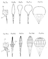
- FIGS. 9a to 9e have shown schematically the evolution of the airfoil behavior of a conventional hemispherical parachute by representing the parachute at five characteristic moments of its opening.
- FIG. 9a represents a deployment bag 90 from which a parachute wing 91 according to the prior art is extracted.
- FIG. 9b it can be seen that the airfoil takes a very elongated ovoid shape and that the air penetrating through the lower part tends to swell the upper part to give it a first pear shape represented in FIG. 9c which goes on. accentuating, as can be seen in FIG. 9d, in order to obtain the complete opening of the parachute in FIG. 9e.
- FIGs 10a to 10e show the deployment of a parachute wing according to the invention provided with its air inlets.
- the deployment bag 100 extracts the airfoil 1, provided with its air inlets according to any one of the variants of the invention and the arrows 101 represent the penetration of air into the airfoil in its lower part as soon as this lower part leaves the deployment bag.
- the arrows 102 show the force resulting from the air inlets which lead to spreading the leading edges in the lower part of the wing. This same lower part tends to deviate before the upper part, as shown in Figures 10c and 10d to obtain a complete deployment in Figure 10e.
- These two operating diagrams clearly show the significant difference in the spacing of the leading edge of the wing due to the presence of the air inlets on the operating diagram of the wing equipped with air inlet according to the invention.
- parachute wings comprising, on the one hand, the air inlets fitted out according to the invention and, on the other hand, maneuvering windows known elsewhere.
- the present invention is not limited to the exemplary embodiments and to the applications which have just been described. In this regard, mention may be made of the application of such a wing at a rapid opening speed for braking aircraft on landing or for early braking of munitions dropped by aircraft.
Landscapes
- Engineering & Computer Science (AREA)
- Aviation & Aerospace Engineering (AREA)
- Toys (AREA)
- Air Bags (AREA)
- Outer Garments And Coats (AREA)
- Tents Or Canopies (AREA)
Claims (7)
- Schnell und zwangsläufig öffnende Fallschirmkappe mit einem Schirm aus Bahnen (24, 25),
dadurch gekennzeichnet, daß
mehrere Bahnen (25), die durch Meridiane (9,10) begrenzt sind, einen Schlitz (6) aufweisen, der so einen ersten und einen zweiten Teil derselben Bahn bildet, ebenso wie eine Tasche, die aus einem Gewebeband besteht, das über dem Schlitz (6) liegt und mit der Bahn (25) über dessen oberen Rand über die Breite des Randes und von einem Meridian zum andern ebenso wie längs der Meridiane (21,23) in Richtung des Angriffsrandes, der den Schirm (2) bildenden Kappe derart verbunden ist, daß ein Lufteintritt gebildet wird, der ein Volumen begrenzt, das zwischen einem Eintrittsbereich (11) und einem Austrittsbereich eingeschlossen ist, der aus dem Schlitz besteht, wobei der Lufteintritt ausschließlich im unteren Teil des Schirms nahe dem Angriffsrand des Schirms liegt, und der Querschnitt des Austrittsbereichs (6) kleiner als der des Eintrittsbereichs (11) ist, um den Lufteintritt aufzublasen und den ihn durchsetzenden Luftstrom zu bremsen. - Fallschirmkappe nach Anspruch 1,
dadurch gekennzeichnet, daß
die seitlichen Enden (9,10) des Bandes (7) mit zwei Meridianen verbunden sind, die die Bahn begrenzen, in der die Tasche ausgebildet ist. - Fallschirmkappe nach Anspruch 1,
dadurch gekennzeichnet, daß
wenigstens ein Gurt (12) den oberen Rand des Schlitzes mit dessen unterem Rand verbindet. - Fallschirmkappe nach Anspruch 1,
wenigstens eine Tasche in wenigstens zwei benachbarten Bahnen (24 und 25) ausgebildet ist, und daß das Band (20) mit zwei Meridianen (21 UND 23) verbunden sind, die auf beiden Seiten der beiden benachbarten Bahnen (24 und 25) liegen. - Fallschirmkappe nach einem der vorhergehenden Ansprüche, gekennzeichnet durch
wenigstens ein Steuerfenster mit wenigstens einer Steuereinrichtung. - Verwendung der Fallschirmkappe nach einem der vorhergehenden Ansprüche beim Fallschirmabsprung aus geringer Höhe.
- Verwendung der Fallschirmkappe nach einem der Ansprüche 1 bis 6 beim Lastenabwurf aus geringer Höhe.
Applications Claiming Priority (2)
| Application Number | Priority Date | Filing Date | Title |
|---|---|---|---|
| FR8517005A FR2590230B1 (fr) | 1985-11-18 | 1985-11-18 | Voilure de parachute |
| FR8517005 | 1985-11-18 |
Publications (3)
| Publication Number | Publication Date |
|---|---|
| EP0225247A1 EP0225247A1 (de) | 1987-06-10 |
| EP0225247B1 EP0225247B1 (de) | 1990-05-30 |
| EP0225247B2 true EP0225247B2 (de) | 1995-04-26 |
Family
ID=9324909
Family Applications (1)
| Application Number | Title | Priority Date | Filing Date |
|---|---|---|---|
| EP86402546A Expired - Lifetime EP0225247B2 (de) | 1985-11-18 | 1986-11-17 | Fallschirmkappe |
Country Status (8)
| Country | Link |
|---|---|
| US (1) | US4739956A (de) |
| EP (1) | EP0225247B2 (de) |
| JP (1) | JP2743171B2 (de) |
| KR (1) | KR930011819B1 (de) |
| CA (1) | CA1325799C (de) |
| DE (1) | DE3671617D1 (de) |
| ES (1) | ES2013982T5 (de) |
| FR (1) | FR2590230B1 (de) |
Families Citing this family (5)
| Publication number | Priority date | Publication date | Assignee | Title |
|---|---|---|---|---|
| JPH0233282U (de) * | 1988-08-29 | 1990-03-01 | ||
| US20060192054A1 (en) * | 2004-10-13 | 2006-08-31 | Lachenmeier Timothy T | Inflatable and deployable systems with three dimensionally reinforced membranes |
| KR101715846B1 (ko) * | 2014-09-29 | 2017-03-14 | 주식회사 진글라이더 | 낙하산 |
| US20250074605A1 (en) * | 2022-03-31 | 2025-03-06 | Nippon Kayaku Kabushiki Kaisha | Parachute, and safety device and flight vehicle provided with parachute |
| CN117446182A (zh) * | 2023-11-16 | 2024-01-26 | 襄阳宏伟航空器有限责任公司 | 降落伞 |
Family Cites Families (13)
| Publication number | Priority date | Publication date | Assignee | Title |
|---|---|---|---|---|
| FR1418752A (de) * | 1900-01-01 | |||
| FR1056062A (fr) * | 1950-11-07 | 1954-02-24 | Pioneer Parachute Co | Parachute perfectionné |
| US2764375A (en) * | 1952-05-05 | 1956-09-25 | Lemoigne Pierre Marcel | Parachute |
| FR1092383A (fr) * | 1953-10-10 | 1955-04-20 | Perfectionnements aux voilures de parachutes | |
| US2929588A (en) * | 1956-05-15 | 1960-03-22 | Northrop Corp | Annular ring parachute |
| US2929888A (en) * | 1957-05-11 | 1960-03-22 | Robert Bosch G M B H Fa | Mounting plate for ignition distributors and housing therefor |
| US3393885A (en) * | 1966-05-31 | 1968-07-23 | Otto W. Neumark | Parachutes |
| FR1536477A (fr) * | 1967-07-13 | 1968-08-16 | Irving Air Chute Gb Ltd | Parachute planeur manoeuvrable |
| US3469805A (en) * | 1967-10-24 | 1969-09-30 | Us Navy | Method for inflating a balloon |
| DE2457056C3 (de) * | 1974-12-03 | 1979-09-06 | Brueggemann & Brand Kg, 5802 Wetter | Gleitfallschirm |
| DE2750278A1 (de) * | 1977-11-10 | 1979-05-17 | Strasilla Dieter | Einrichtung zum vorwaertsbewegenden antreiben eines koerpers mittels durch besegelung ausgenutzter windkraft |
| US4588149A (en) * | 1984-09-20 | 1986-05-13 | The United States Of America As Represented By The Secretary Of The Navy | Lowered opening shock parachute canopy |
| JP2607301Y2 (ja) * | 1997-05-06 | 2001-07-09 | 九州日立マクセル株式会社 | 浄水器 |
-
1985
- 1985-11-18 FR FR8517005A patent/FR2590230B1/fr not_active Expired - Lifetime
-
1986
- 1986-11-17 US US06/931,646 patent/US4739956A/en not_active Expired - Lifetime
- 1986-11-17 EP EP86402546A patent/EP0225247B2/de not_active Expired - Lifetime
- 1986-11-17 CA CA000523133A patent/CA1325799C/en not_active Expired - Lifetime
- 1986-11-17 DE DE8686402546T patent/DE3671617D1/de not_active Expired - Lifetime
- 1986-11-17 ES ES86402546T patent/ES2013982T5/es not_active Expired - Lifetime
- 1986-11-18 JP JP61273090A patent/JP2743171B2/ja not_active Expired - Lifetime
- 1986-11-18 KR KR1019860009736A patent/KR930011819B1/ko not_active Expired - Fee Related
Also Published As
| Publication number | Publication date |
|---|---|
| JPS62120297A (ja) | 1987-06-01 |
| US4739956A (en) | 1988-04-26 |
| EP0225247A1 (de) | 1987-06-10 |
| DE3671617D1 (de) | 1990-07-05 |
| JP2743171B2 (ja) | 1998-04-22 |
| FR2590230B1 (fr) | 1991-05-03 |
| FR2590230A1 (fr) | 1987-05-22 |
| ES2013982T5 (es) | 1995-08-16 |
| ES2013982B3 (es) | 1990-12-16 |
| EP0225247B1 (de) | 1990-05-30 |
| CA1325799C (en) | 1994-01-04 |
| KR930011819B1 (ko) | 1993-12-21 |
| KR870004881A (ko) | 1987-06-02 |
| ES2013982A4 (es) | 1990-06-16 |
Similar Documents
| Publication | Publication Date | Title |
|---|---|---|
| EP0050542B1 (de) | Flugzeugflügel mit einer auftrieberhöhenden Vorrichtung an der Nase der Tragfläche und Flugzeug mit einem derartigen Flügel | |
| EP0202271B1 (de) | Antriebsflügel mit aufblasbarer armatur | |
| EP1371552B1 (de) | Gelenkvorrichtung zur Verbindung einer Klappe zu einer aerodynamischen Fläche eines Luftfahrzeuges | |
| EP0601910B1 (de) | Schubumkehrklappe mit Deflektoren zur Strahlbeeinflussung | |
| US4811920A (en) | Aerial device | |
| EP0225247B1 (de) | Fallschirmkappe | |
| CH377215A (fr) | Voile de bateau et procédé pour sa fabrication | |
| EP4085189B1 (de) | Schubumkehrvorrichtung mit türen und mindestens einem zurückziehbaren deflektor zum verschliessen einer seitlichen öffnung | |
| FR2582615A1 (fr) | Helicoptere a partie arriere de fuselage et a poutre de queue de section ogivale | |
| WO2010061071A2 (fr) | Nacelle integree sur aile volante | |
| CH617896A5 (de) | ||
| FR2562029A1 (fr) | Voilure polymanoeuvrable et procede de commande d'une telle voilure | |
| EP1658221B1 (de) | Starrer flügel mit variablem auftrieb aufgrund des ausklappens eines flexiblen flügels | |
| JPH01306396A (ja) | 滑空用パラシュート | |
| FR2558791A1 (fr) | Parachute a voilure multicellulaire | |
| FR2610288A1 (fr) | Voilure souple pour un parachute ou pour un appareil destine au vol de pente, au vol ascensionnel ou au vol motorise | |
| FR2863583A1 (fr) | Carenage de rotor de giravion | |
| EP0044251B1 (de) | Pyrotechnische Vorrichtung zum Abtrennen und Ausschleudern eines durchsichtigen Flugzeugkabinendachs | |
| EP0445186A1 (de) | Flugdrachenstruktur von aufblasbarem stauluftkammertyp | |
| FR2722471A1 (fr) | Parachute en forme d'aile a nervures partielles | |
| BE1032402B1 (fr) | Système de déplacement d'un volet mobile de bord d'attaque d'une aile d'aéronef, comprenant un carénage aérodynamique agencé autour d'un rail de ce système | |
| FR2749563A1 (fr) | Parapente avec boudin gonflable transversal | |
| EP0575344B1 (de) | Fliegendes fahrzeug, wie motorisiertes ultraleichtes flugzeug | |
| EP1308386A1 (de) | Gleiter mit Düsenanordnung für einen Fallschirm | |
| FR2610893A1 (fr) | Volet pour parachute-aile |
Legal Events
| Date | Code | Title | Description |
|---|---|---|---|
| PUAI | Public reference made under article 153(3) epc to a published international application that has entered the european phase |
Free format text: ORIGINAL CODE: 0009012 |
|
| AK | Designated contracting states |
Kind code of ref document: A1 Designated state(s): DE ES FR GB GR IT |
|
| 17P | Request for examination filed |
Effective date: 19870601 |
|
| 17Q | First examination report despatched |
Effective date: 19880120 |
|
| GRAA | (expected) grant |
Free format text: ORIGINAL CODE: 0009210 |
|
| ITF | It: translation for a ep patent filed | ||
| AK | Designated contracting states |
Kind code of ref document: B1 Designated state(s): DE ES FR GB GR IT |
|
| GBT | Gb: translation of ep patent filed (gb section 77(6)(a)/1977) | ||
| REF | Corresponds to: |
Ref document number: 3671617 Country of ref document: DE Date of ref document: 19900705 |
|
| REG | Reference to a national code |
Ref country code: GR Ref legal event code: FG4A Free format text: 3000643 |
|
| PLBI | Opposition filed |
Free format text: ORIGINAL CODE: 0009260 |
|
| 26 | Opposition filed |
Opponent name: WARDLE STOREYS (SAFETY AND SURVIVAL EQUIPMENT) LIM Effective date: 19910226 |
|
| PG25 | Lapsed in a contracting state [announced via postgrant information from national office to epo] |
Ref country code: FR Effective date: 19910731 |
|
| REG | Reference to a national code |
Ref country code: FR Ref legal event code: ST |
|
| ITTA | It: last paid annual fee | ||
| PUAH | Patent maintained in amended form |
Free format text: ORIGINAL CODE: 0009272 |
|
| STAA | Information on the status of an ep patent application or granted ep patent |
Free format text: STATUS: PATENT MAINTAINED AS AMENDED |
|
| 27A | Patent maintained in amended form |
Effective date: 19950426 |
|
| AK | Designated contracting states |
Kind code of ref document: B2 Designated state(s): DE ES FR GB GR IT |
|
| PG25 | Lapsed in a contracting state [announced via postgrant information from national office to epo] |
Ref country code: GR Free format text: THE PATENT HAS BEEN ANNULLED BY A DECISION OF A NATIONAL AUTHORITY Effective date: 19950614 |
|
| ITF | It: translation for a ep patent filed | ||
| REG | Reference to a national code |
Ref country code: ES Ref legal event code: DC2A Kind code of ref document: T5 Effective date: 19950816 |
|
| GBTA | Gb: translation of amended ep patent filed (gb section 77(6)(b)/1977) |
Effective date: 19950802 |
|
| REG | Reference to a national code |
Ref country code: GR Ref legal event code: FG4A Free format text: 3016433 |
|
| REG | Reference to a national code |
Ref country code: GB Ref legal event code: IF02 |
|
| PGFP | Annual fee paid to national office [announced via postgrant information from national office to epo] |
Ref country code: DE Payment date: 20031127 Year of fee payment: 18 Ref country code: GR Payment date: 20031127 Year of fee payment: 18 |
|
| PG25 | Lapsed in a contracting state [announced via postgrant information from national office to epo] |
Ref country code: DE Free format text: LAPSE BECAUSE OF NON-PAYMENT OF DUE FEES Effective date: 20050601 |
|
| APAH | Appeal reference modified |
Free format text: ORIGINAL CODE: EPIDOSCREFNO |
|
| PGFP | Annual fee paid to national office [announced via postgrant information from national office to epo] |
Ref country code: GB Payment date: 20051116 Year of fee payment: 20 |
|
| PG25 | Lapsed in a contracting state [announced via postgrant information from national office to epo] |
Ref country code: IT Free format text: LAPSE BECAUSE OF NON-PAYMENT OF DUE FEES;WARNING: LAPSES OF ITALIAN PATENTS WITH EFFECTIVE DATE BEFORE 2007 MAY HAVE OCCURRED AT ANY TIME BEFORE 2007. THE CORRECT EFFECTIVE DATE MAY BE DIFFERENT FROM THE ONE RECORDED. Effective date: 20051117 |
|
| PGFP | Annual fee paid to national office [announced via postgrant information from national office to epo] |
Ref country code: ES Payment date: 20051219 Year of fee payment: 20 |
|
| PG25 | Lapsed in a contracting state [announced via postgrant information from national office to epo] |
Ref country code: GB Free format text: LAPSE BECAUSE OF EXPIRATION OF PROTECTION Effective date: 20061116 |
|
| PG25 | Lapsed in a contracting state [announced via postgrant information from national office to epo] |
Ref country code: ES Free format text: LAPSE BECAUSE OF EXPIRATION OF PROTECTION Effective date: 20061118 |
|
| REG | Reference to a national code |
Ref country code: GB Ref legal event code: PE20 |
|
| REG | Reference to a national code |
Ref country code: ES Ref legal event code: FD2A Effective date: 20061118 |