EP0224931A2 - Pallet changing system for a machine tool - Google Patents
Pallet changing system for a machine tool Download PDFInfo
- Publication number
- EP0224931A2 EP0224931A2 EP86116905A EP86116905A EP0224931A2 EP 0224931 A2 EP0224931 A2 EP 0224931A2 EP 86116905 A EP86116905 A EP 86116905A EP 86116905 A EP86116905 A EP 86116905A EP 0224931 A2 EP0224931 A2 EP 0224931A2
- Authority
- EP
- European Patent Office
- Prior art keywords
- pallet
- fork
- standby station
- ing
- receiving member
- Prior art date
- Legal status (The legal status is an assumption and is not a legal conclusion. Google has not performed a legal analysis and makes no representation as to the accuracy of the status listed.)
- Granted
Links
- 238000003491 array Methods 0.000 claims abstract description 12
- 230000008093 supporting effect Effects 0.000 claims abstract description 12
- 230000006872 improvement Effects 0.000 claims 1
- 239000003638 chemical reducing agent Substances 0.000 description 1
- 238000006073 displacement reaction Methods 0.000 description 1
- 238000009434 installation Methods 0.000 description 1
- 238000003754 machining Methods 0.000 description 1
- 230000002093 peripheral effect Effects 0.000 description 1
Images


Classifications
-
- B—PERFORMING OPERATIONS; TRANSPORTING
- B23—MACHINE TOOLS; METAL-WORKING NOT OTHERWISE PROVIDED FOR
- B23Q—DETAILS, COMPONENTS, OR ACCESSORIES FOR MACHINE TOOLS, e.g. ARRANGEMENTS FOR COPYING OR CONTROLLING; MACHINE TOOLS IN GENERAL CHARACTERISED BY THE CONSTRUCTION OF PARTICULAR DETAILS OR COMPONENTS; COMBINATIONS OR ASSOCIATIONS OF METAL-WORKING MACHINES, NOT DIRECTED TO A PARTICULAR RESULT
- B23Q7/00—Arrangements for handling work specially combined with or arranged in, or specially adapted for use in connection with, machine tools, e.g. for conveying, loading, positioning, discharging, sorting
- B23Q7/10—Arrangements for handling work specially combined with or arranged in, or specially adapted for use in connection with, machine tools, e.g. for conveying, loading, positioning, discharging, sorting by means of magazines
-
- B—PERFORMING OPERATIONS; TRANSPORTING
- B23—MACHINE TOOLS; METAL-WORKING NOT OTHERWISE PROVIDED FOR
- B23Q—DETAILS, COMPONENTS, OR ACCESSORIES FOR MACHINE TOOLS, e.g. ARRANGEMENTS FOR COPYING OR CONTROLLING; MACHINE TOOLS IN GENERAL CHARACTERISED BY THE CONSTRUCTION OF PARTICULAR DETAILS OR COMPONENTS; COMBINATIONS OR ASSOCIATIONS OF METAL-WORKING MACHINES, NOT DIRECTED TO A PARTICULAR RESULT
- B23Q7/00—Arrangements for handling work specially combined with or arranged in, or specially adapted for use in connection with, machine tools, e.g. for conveying, loading, positioning, discharging, sorting
- B23Q7/14—Arrangements for handling work specially combined with or arranged in, or specially adapted for use in connection with, machine tools, e.g. for conveying, loading, positioning, discharging, sorting co-ordinated in production lines
- B23Q7/1426—Arrangements for handling work specially combined with or arranged in, or specially adapted for use in connection with, machine tools, e.g. for conveying, loading, positioning, discharging, sorting co-ordinated in production lines with work holders not rigidly fixed to the transport devices
- B23Q7/1431—Work holder changers
-
- Y—GENERAL TAGGING OF NEW TECHNOLOGICAL DEVELOPMENTS; GENERAL TAGGING OF CROSS-SECTIONAL TECHNOLOGIES SPANNING OVER SEVERAL SECTIONS OF THE IPC; TECHNICAL SUBJECTS COVERED BY FORMER USPC CROSS-REFERENCE ART COLLECTIONS [XRACs] AND DIGESTS
- Y10—TECHNICAL SUBJECTS COVERED BY FORMER USPC
- Y10T—TECHNICAL SUBJECTS COVERED BY FORMER US CLASSIFICATION
- Y10T29/00—Metal working
- Y10T29/51—Plural diverse manufacturing apparatus including means for metal shaping or assembling
- Y10T29/5196—Multiple station with conveyor
Definitions
- This invention relates to a system for supplying a plurality of pallets one after another to the machining center of a machine tool.
- the pallets and the workpieces carried thereon add to the total weight of the load which must be rotated in an indexed pattern. It is difficult to rotate them quickly in an accurately indexed way.
- a drum having a larger radius is required for carrying a larger stock of pallets and makes more difficult the problem which has hereinabove been pointed out.
- the other system includes a plurality of fixed racks arranged along a plurality of horizontal lines in a vertical plane. It requires a smaller floor space than the system including a drum. It, however, includes a stacker crane adapted for traveling along the racks to load or unload the pallets. This crane is expensive. More strictlyover, the traveling crane requires a floor space which is substantially equal to the space occupied by the racks. Therefore, the system still requires a considerably large floor space.
- a system which essentially comprises a plurality of fixed racks arranged in a plurality of circular arrays located one above another and a fork provided in the center of those circular arrays horizontally rotatably, vertically movably and longitudinally movably, while carrying a pallet at one end thereof.
- the circular arrays of the racks having a sufficiently large diameter to enable the storage of a sufficiently large number of pallets provide in their center a sufficiently large space for the location of the fork.
- the location of the fork and other devices associated therewith within the space defined by the circular arrays enables the system of this invention to utilize the floor space more effectively than any system known in the art. It also enables a reduction in the weight of the fork and other devices associated therewith and thereby the quick rotation thereof in an accurately indexed way.
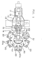
- FIGURE l A system embodying this invention is generally shown in FIGURE l with a machine tool having a bed l0, a column ll supported slidably on the bed l0, a spindle head l2 supported vertically movably on the column ll and a table l3 on which a pallet P is removably supported.
- the column ll is horizontally movable to and away from the table l3.
- the system includes a pallet rest l4 a defining a standby station l4, a pallet changing device l5, a plurality of shelves 20 each having a plurality of vertically spaced apart pallet racks and a loading and unloading station 2l.
- the pallet changing device l5 is horizontally rotatable for exchanging the pallet P on the table l3 with another pallet on the pallet rest l4 a .
- the racks of the shelves form a plurality of circular arrays of racks of which the pallet rest l4 a forms a part.
- a pallet loading and unloading device 30 is provided in the center of the circular arrays of the shelves 20.
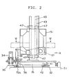
- the device 30 is shown in detail in FIGURES 2 and 3.
- a toothed wheel 32 is secured to a base 3l and has an upper surface and an inner peripheral surface which define guide surfaces for rollers 4l and 42.
- a rotary table 33 is rotatably supported by the rollers 4l and 42 on the guide surfaces of the toothed wheel 32.
- a pinion 35 connected to a motor 34 is rotatably supported on the rotary table 33 and meshes with the toothed wheel 32.
- the toothed wheel 32 has plural knock holes 32 a .
- a knock pin 36 is provided in a guide tube 37 longitudinally movably into or away from the knock hole 32 a .
- the knock pin 36 has an upper end to which a cylinder 38 is connected.
- a pair of guide posts 43 and 44 are upstanding from the rotary table 33.
- a pair of vertical rails 45 and 46 are secured to the mutually facing surfaces of the guide posts 43 and 44, respectively.
- a vertically movable structure 5l has a plurality of rollers 47 and 48 rotatably contacting both sides of the rails 45 and 46, respectively, and a plurality of rollers 49 and 50 contacting the mutually facing surfaces of the rails 45 and 46, respectively.
- a rack bar 52 or 53 is secured to one side of each guide post 43 or 44, respectively.
- a shaft 54 is rotatably supported by the vertically movable structure 5l.
- a pair of pinions 55 and 56 are provided at both ends, respectively, of the shaft 54 and mesh with the rack bars 52 and 53, respectively.
- a sprocket 57 is secured to the shaft 54 and connected by a chain 6l to a driving sprocket 60 which is adapted to be driven by a motor 58 and a speed reducer 59.
- a cylinder 62 is provided for preventing the vertically movable structure 5l from falling inadvertently. It has a member which is engageable with a stopper not shown to maintain the structure 5l at an appropriate level of height for handling the pallet on a particular rack in a particular shelf 20.
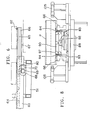
- a pair of parallel guide rails 63 are horizontally supported on the structure 5l, as shown in FIGURES 5 and 6.
- a plurality of rollers 64 are provided on each of the inner or mutually facing surfaces of the guide rails 63.
- a shift fork 66 has a pair of side grooves 65 in which the rollers 64 of the guide rails 63, respectively, are received.
- the fork 66 has a lower surface to which a rack bar 67 is secured.
- a pinion 68 meshes with the rack bar 67 and is operationally connected to a motor 80 by gears 69 and 70.
- the fork 66 has an upper surface which is provided at one end thereof with sheet members 8l defining a pallet supporting surface and a plurality of pallet positioning pins 82.
- the pallet supporting portion of the fork 66 is so positioned as to be offset forward by an appropriate distance beyond the center of its rotation when the fork 66 has been retracted, so that it may have a small stroke of movement when delivering a pallet.
- the fork 66 has a bifurcated end portion defining a U-shaped inner periphery on which a pair of guide surfaces 84 are formed.
- the standby station has two guide projections 83 which are engageable with the guide surfaces 84, respectively, to position the fork 66 transversely in place when it has been advanced.
- FIGURE 8 showing the delivery of the pallet P from the form 66 to the standby station l4.
- the fork 66 carrying the pallet P as shown by two-dot chain lines is advanced and when it has approached the forward end of its stroke, its guide surfaces 84 engage the guide projections 83, whereby any transverse displacement of the fork is corrected.
- the standby station l4 has a pallet receiving member 90 which is in its lowered position as shown by two-dot chain lines.
- the pallet receiving member 90 is raised to its raised position as shown by solid lines for receiving the pallet P from the fork 66.
- the pallet changing device l5 has a hook member l02 with which two pallets are engageable, and each pallet has a projection 9l which is engageable with the hook member l02.
- the pallet P on the pallet receiving member 90 is now ready to replace the pallet on the table l3, as will hereinafter be described in detail.
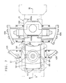
- the pallet changing device l5 will now be described in further detail with reference to FIGURES 7 to 9.
- the standby station l4 has a base 89 on which a cylinder 92 is provided for raising and lowering the pallet receiving member 90.
- the cylinder 92 contains a piston 93 and a piston rod 94 extending from the piston 93 is connected to the pallet receiving member 90.
- a guide rod 95 extends from the bottom of the pallet receiving member 90 and is held in a guide tube, 96 so that the member 90 may not turn.
- the pallet receiving member 90 is provided at each of its front and rear ends with an arcuate array of rollers 97 on which the pallet P can rest.
- the pallet changing device 15 has a base l00 supported on the base 89 and supporting a vertical shaft l0l rotatably.
- the shaft l0l has an upper end to which the hook member l02 is secured.
- a pinion l03 is provided under the shaft l0l and meshes with a rack piston l04.
- the piston l04 is movable to rotate the hook member l02 by an angle of l80°.
- the pallet P on the machine table l3 is held by a pallet clamper not shown in its lowered position as shown by two-dot chain lines in FIGURE 9 when the workpiece on the pallet is machined.
- the pallet clamper When the pallet P on the table l3 is changed, however, the pallet clamper is raised and the projection 9l of the pallet P is engaged with the hook member l02.
- the hook member l02 When the projections 9l of the two pallets P have both been engaged with the hook member l02, the hook member l02 is rotated by l80° so to transfer one of the pallets P from the table l3 to the standby station l4 and the other pallet P from the standby station l4 to the table l3. Then, the pallet clamper and the pallet receiving member 90 are lowered, whereupon the projections 9l of the two pallets 9l are both disengaged from the hook member l02 and the pallet P on the table l3 is lowered to the machining position.
- a plurality of arcuate supporting members l05 and l06 are provided for supporting the pallets P when the hook member l02 is rotating.
- the pallet P which has been transferred from the table l3 to the standby station l4 is raised by the pallet receiving member 90 and the fork 66 is advanced to a position below the pallet P. Then, the pallet receiving member 90 is lowered to transfer the pallet P onto the fork 66. The fork 66 is retracted, the rotary table 33 is rotated and the vertically movable structure 5l is raised or lowered to a position which is appropriate for the transfer of the pallet P to an empty rack 20 a in one of the shelves 20.
- the structure 5l is positioned at a level of height slightly above the pallet supporting position of the rack 20 a .
- the fork 66 is advanced and the structure 5l is slightly lowered so that the pallet P may be transferred from the fork 66 to the rack 20 a .
- the rotary table 33 is rotated and the structure 5l is raised or lowered to bring the fork 66 to a position which is appropriate for receiving from another rack the pallet P carrying the workpiece to be machined.
- the fork 66 is positioned slightly below the pallet supporting position of the rack and advanced until its pallet receiving portion is located below the pallet.
- the structure 5l is slightly raised so that the fork 66 may receive the pallet from the rack.
- the fork 66 carrying the pallet thereon is retracted, rotated and raised or lowered to transfer the pallet to the standby station l4.
- the rotary table 33, the vertically movable structure 5l and the fork 66 are likewise operated for transferring the pallets to the loading and unloading station 2l or receiving them therefrom.
- the location of the pallet loading and unloading device 30 in the space sur severelyrounded by the circular arrays of the shelves 20 makes it possible to utilize very effectively the floor space which is occupied by the system.
- the arrangement of a plurality of racks one above another in each shelf enables a small space to be effectively utilized for stocking a large number of pallets.
- the racks can be of the type which is stationary and is, therefore, inexpensive.
- the pallet loading and unloading device which is rotatable, is greatly smaller in weight than any conventional structure of the type in which a shelf or shelves carrying a plurality of pallets are rotated.
- the device can, therefore, be rotated quickly and positioned accurately, as opposed to any such conventional structure.
Landscapes
- Engineering & Computer Science (AREA)
- Mechanical Engineering (AREA)
- Feeding Of Workpieces (AREA)
- Multi-Process Working Machines And Systems (AREA)
- Warehouses Or Storage Devices (AREA)
Abstract
Description
- This invention relates to a system for supplying a plurality of pallets one after another to the machining center of a machine tool.
- There are two ways of storing the pallets which are going to be supplied to the machining center of a machine tool. One of the ways is to stock a plurality of pallets in a horizontal plane and the other way is to stock them in a vertical plane or stack. The former way has the disadvantage of requiring a very large floor space if a large number of pallets are stocked. The latter way has the advantage of requiring only a smaller floor space. Two systems are available for carrying it out. One of them includes a rotatable drum and an elevator installed outside the drum. The vertical movement of the elevator and the rotation of the drum in an indexed pattern are utilized for loading or unloading a particular pallet. The drum is very large and heavy. The pallets and the workpieces carried thereon add to the total weight of the load which must be rotated in an indexed pattern. It is difficult to rotate them quickly in an accurately indexed way. A drum having a larger radius is required for carrying a larger stock of pallets and makes more difficult the problem which has hereinabove been pointed out.
- The other system includes a plurality of fixed racks arranged along a plurality of horizontal lines in a vertical plane. It requires a smaller floor space than the system including a drum. It, however, includes a stacker crane adapted for traveling along the racks to load or unload the pallets. This crane is expensive. Moreover, the traveling crane requires a floor space which is substantially equal to the space occupied by the racks. Therefore, the system still requires a considerably large floor space.
- It is, therefore, an object of this invention to provide a pallet changing system for a machine tool which requires only a small floor space for installation, and which can quickly change a plurality of pallets one after another.
- It is another object of this invention to provide a pallet changing system which can quickly be rotated horizontally for changing the pallets.
- These objects are attained by a system which essentially comprises a plurality of fixed racks arranged in a plurality of circular arrays located one above another and a fork provided in the center of those circular arrays horizontally rotatably, vertically movably and longitudinally movably, while carrying a pallet at one end thereof.
- The circular arrays of the racks having a sufficiently large diameter to enable the storage of a sufficiently large number of pallets provide in their center a sufficiently large space for the location of the fork. The location of the fork and other devices associated therewith within the space defined by the circular arrays enables the system of this invention to utilize the floor space more effectively than any system known in the art. It also enables a reduction in the weight of the fork and other devices associated therewith and thereby the quick rotation thereof in an accurately indexed way.
-
- FIGURE l is a top plan view of a system embodying this invention;
- FIGURE 2 is a front elevational view, partly in section, of a pallet loading and unloading device;
- FIGURE 3 is a side elevational view taken along the line of an arrow A in FIGURE 2 and showing a mechanism for moving a vertically movable structure;
- FIGURE 4 is a top plan view of the device shown in FIGURE 2;
- FIGURE 5 is a sectional view taken along the line V-V of FIGURE 2;
- FIGURE 6 is a sectional view taken along the line VI-VI of FIGURE 5;
- FIGURE 7 is a top plan view of a pallet changing device;
- FIGURE 8 is an elevational view taken along the line of an arrow B in FIGURE 7; and
- FIGURE 9 is a sectional view taken along the line of IX-IX of FIGURE 7.
- A system embodying this invention is generally shown in FIGURE l with a machine tool having a bed l0, a column ll supported slidably on the bed l0, a spindle head l2 supported vertically movably on the column ll and a table l3 on which a pallet P is removably supported. The column ll is horizontally movable to and away from the table l3. The system includes a pallet rest l4a defining a standby station l4, a pallet changing device l5, a plurality of
shelves 20 each having a plurality of vertically spaced apart pallet racks and a loading and unloading station 2l. The pallet changing device l5 is horizontally rotatable for exchanging the pallet P on the table l3 with another pallet on the pallet rest l4a. The racks of the shelves form a plurality of circular arrays of racks of which the pallet rest l4a forms a part. - A pallet loading and
unloading device 30 is provided in the center of the circular arrays of theshelves 20. Thedevice 30 is shown in detail in FIGURES 2 and 3. Atoothed wheel 32 is secured to a base 3l and has an upper surface and an inner peripheral surface which define guide surfaces forrollers 4l and 42. A rotary table 33 is rotatably supported by therollers 4l and 42 on the guide surfaces of thetoothed wheel 32. Apinion 35 connected to amotor 34 is rotatably supported on the rotary table 33 and meshes with thetoothed wheel 32. Thetoothed wheel 32 hasplural knock holes 32a. Aknock pin 36 is provided in aguide tube 37 longitudinally movably into or away from theknock hole 32a. Theknock pin 36 has an upper end to which acylinder 38 is connected. A pair ofguide posts vertical rails guide posts rollers rails rollers rails rack bar guide post shaft 54 is rotatably supported by the vertically movable structure 5l. A pair ofpinions shaft 54 and mesh with therack bars sprocket 57 is secured to theshaft 54 and connected by a chain 6l to a drivingsprocket 60 which is adapted to be driven by amotor 58 and aspeed reducer 59. Acylinder 62 is provided for preventing the vertically movable structure 5l from falling inadvertently. It has a member which is engageable with a stopper not shown to maintain the structure 5l at an appropriate level of height for handling the pallet on a particular rack in aparticular shelf 20. - A pair of
parallel guide rails 63 are horizontally supported on the structure 5l, as shown in FIGURES 5 and 6. A plurality ofrollers 64 are provided on each of the inner or mutually facing surfaces of theguide rails 63. Ashift fork 66 has a pair ofside grooves 65 in which therollers 64 of theguide rails 63, respectively, are received. Thefork 66 has a lower surface to which arack bar 67 is secured. Apinion 68 meshes with therack bar 67 and is operationally connected to amotor 80 bygears fork 66 has an upper surface which is provided at one end thereof with sheet members 8l defining a pallet supporting surface and a plurality of pallet positioning pins 82. The pallet supporting portion of thefork 66 is so positioned as to be offset forward by an appropriate distance beyond the center of its rotation when thefork 66 has been retracted, so that it may have a small stroke of movement when delivering a pallet. Thefork 66 has a bifurcated end portion defining a U-shaped inner periphery on which a pair of guide surfaces 84 are formed. The standby station has twoguide projections 83 which are engageable with the guide surfaces 84, respectively, to position thefork 66 transversely in place when it has been advanced. - Reference is now made to FIGURE 8 showing the delivery of the pallet P from the
form 66 to the standby station l4. Thefork 66 carrying the pallet P as shown by two-dot chain lines is advanced and when it has approached the forward end of its stroke, its guide surfaces 84 engage theguide projections 83, whereby any transverse displacement of the fork is corrected. The standby station l4 has apallet receiving member 90 which is in its lowered position as shown by two-dot chain lines. Thepallet receiving member 90 is raised to its raised position as shown by solid lines for receiving the pallet P from thefork 66. The pallet changing device l5 has a hook member l02 with which two pallets are engageable, and each pallet has a projection 9l which is engageable with the hook member l02. The pallet P on thepallet receiving member 90 is now ready to replace the pallet on the table l3, as will hereinafter be described in detail. - The pallet changing device l5 will now be described in further detail with reference to FIGURES 7 to 9. The standby station l4 has a base 89 on which a
cylinder 92 is provided for raising and lowering thepallet receiving member 90. Thecylinder 92 contains apiston 93 and apiston rod 94 extending from thepiston 93 is connected to thepallet receiving member 90. Aguide rod 95 extends from the bottom of thepallet receiving member 90 and is held in a guide tube, 96 so that themember 90 may not turn. Thepallet receiving member 90 is provided at each of its front and rear ends with an arcuate array ofrollers 97 on which the pallet P can rest. Thepallet changing device 15 has a base l00 supported on thebase 89 and supporting a vertical shaft l0l rotatably. The shaft l0l has an upper end to which the hook member l02 is secured. A pinion l03 is provided under the shaft l0l and meshes with a rack piston l04. The piston l04 is movable to rotate the hook member l02 by an angle of l80°. The pallet P on the machine table l3 is held by a pallet clamper not shown in its lowered position as shown by two-dot chain lines in FIGURE 9 when the workpiece on the pallet is machined. When the pallet P on the table l3 is changed, however, the pallet clamper is raised and the projection 9l of the pallet P is engaged with the hook member l02. When the projections 9l of the two pallets P have both been engaged with the hook member l02, the hook member l02 is rotated by l80° so to transfer one of the pallets P from the table l3 to the standby station l4 and the other pallet P from the standby station l4 to the table l3. Then, the pallet clamper and thepallet receiving member 90 are lowered, whereupon the projections 9l of the two pallets 9l are both disengaged from the hook member l02 and the pallet P on the table l3 is lowered to the machining position. A plurality of arcuate supporting members l05 and l06 are provided for supporting the pallets P when the hook member l02 is rotating. - Description will now be made of the operation of the pallet loading and unloading
device 30. The pallet P which has been transferred from the table l3 to the standby station l4 is raised by thepallet receiving member 90 and thefork 66 is advanced to a position below the pallet P. Then, thepallet receiving member 90 is lowered to transfer the pallet P onto thefork 66. Thefork 66 is retracted, the rotary table 33 is rotated and the vertically movable structure 5l is raised or lowered to a position which is appropriate for the transfer of the pallet P to anempty rack 20a in one of theshelves 20. The structure 5l is positioned at a level of height slightly above the pallet supporting position of therack 20a. Then, thefork 66 is advanced and the structure 5l is slightly lowered so that the pallet P may be transferred from thefork 66 to therack 20a. After thefork 66 has been retracted again, the rotary table 33 is rotated and the structure 5l is raised or lowered to bring thefork 66 to a position which is appropriate for receiving from another rack the pallet P carrying the workpiece to be machined. Thefork 66 is positioned slightly below the pallet supporting position of the rack and advanced until its pallet receiving portion is located below the pallet. Then, the structure 5l is slightly raised so that thefork 66 may receive the pallet from the rack. Thefork 66 carrying the pallet thereon is retracted, rotated and raised or lowered to transfer the pallet to the standby station l4. The rotary table 33, the vertically movable structure 5l and thefork 66 are likewise operated for transferring the pallets to the loading and unloading station 2l or receiving them therefrom. - According to this invention, the location of the pallet loading and unloading
device 30 in the space surrounded by the circular arrays of theshelves 20 makes it possible to utilize very effectively the floor space which is occupied by the system. The arrangement of a plurality of racks one above another in each shelf enables a small space to be effectively utilized for stocking a large number of pallets. As the pallet loading and unloadingdevice 30 is rotatable and vertically movable and includes a fork which is movable to and away from any of the racks, the racks can be of the type which is stationary and is, therefore, inexpensive. The pallet loading and unloading device, which is rotatable, is greatly smaller in weight than any conventional structure of the type in which a shelf or shelves carrying a plurality of pallets are rotated. The device can, therefore, be rotated quickly and positioned accurately, as opposed to any such conventional structure.
Claims (5)
a plurality of pallet storing shelves arranged in a plurality of concentric circular arrays and each having a plurality of pallet supporting racks located one above another, said standby station forming a part of said circular arrays, said arrays defining a central space surrounded by said racks;
a rotary table disposed rotatably in the center of said space;
a pair of guide posts upstanding from said rotary table;
a structure supported vertically movably on said posts;
a pallet handling fork provided on said structure horizontally movably to and away from said standby station;
a pair of guide rails along which said fork is horizontally movable;
said fork having one end defining a pallet supporting portion;
a device for rotating said rotary table in an indexed way;
a device for moving said vertically movable structure vertically; and
a device for moving said fork horizontally.
Applications Claiming Priority (2)
| Application Number | Priority Date | Filing Date | Title |
|---|---|---|---|
| JP275589/85 | 1985-12-06 | ||
| JP60275589A JPH0616977B2 (en) | 1985-12-06 | 1985-12-06 | Pallet loading / unloading device |
Publications (3)
| Publication Number | Publication Date |
|---|---|
| EP0224931A2 true EP0224931A2 (en) | 1987-06-10 |
| EP0224931A3 EP0224931A3 (en) | 1989-05-10 |
| EP0224931B1 EP0224931B1 (en) | 1992-08-19 |
Family
ID=17557559
Family Applications (1)
| Application Number | Title | Priority Date | Filing Date |
|---|---|---|---|
| EP86116905A Expired - Lifetime EP0224931B1 (en) | 1985-12-06 | 1986-12-04 | Pallet changing system for a machine tool |
Country Status (4)
| Country | Link |
|---|---|
| US (1) | US4781512A (en) |
| EP (1) | EP0224931B1 (en) |
| JP (1) | JPH0616977B2 (en) |
| DE (1) | DE3686476T2 (en) |
Cited By (9)
| Publication number | Priority date | Publication date | Assignee | Title |
|---|---|---|---|---|
| DE3923574C1 (en) * | 1989-07-17 | 1990-10-25 | Maho Ag, 8962 Pfronten, De | |
| EP0356216A3 (en) * | 1988-08-23 | 1992-02-26 | Kabushiki Kaisha Mori Seiki Seisakusho | Automatic pallet changer |
| EP0468207A3 (en) * | 1990-07-21 | 1992-09-23 | Robert Bosch Gmbh | Table with a system for changing equipment |
| US5174709A (en) * | 1991-03-06 | 1992-12-29 | Leland D. Blatt | Workpiece transfer device |
| EP0529465A1 (en) * | 1991-08-21 | 1993-03-03 | Automation International, Inc. | Apparatus and method for lifting and transporting palletized workpieces |
| US5222285A (en) * | 1990-06-20 | 1993-06-29 | Matsuura Machinery Corporation | Pallet storage device and a pallet exchange device for a machine tool, and a lathe with an automatically removable pallet |
| US5452981A (en) * | 1991-03-06 | 1995-09-26 | Leland D. Blatt | Automatic tool changer |
| GB2301338A (en) * | 1995-08-26 | 1996-12-04 | Bleichert Foerderanlagen Gmbh | A Handling System for Workpieces |
| EP2511044A3 (en) * | 2011-04-11 | 2014-01-29 | LIEBHERR-VERZAHNTECHNIK GmbH | Manufacturing system |
Families Citing this family (23)
| Publication number | Priority date | Publication date | Assignee | Title |
|---|---|---|---|---|
| JPH0818216B2 (en) * | 1987-10-26 | 1996-02-28 | 豊田工機株式会社 | Pallet delivery device by stacker crane |
| JPH01240261A (en) * | 1988-03-19 | 1989-09-25 | Osaka Kiko Co Ltd | Composite machine tool |
| DE3810171C2 (en) * | 1988-03-25 | 1993-11-04 | Manfred Bareis | DEVICE FOR CLAMPING A CHANGEABLE PLATE WITH WORKPIECES ON A WORKING TABLE OF A MACHINE TOOL |
| US5052540A (en) * | 1988-07-26 | 1991-10-01 | Honda Giken Kogyo Kabushiki Kaisha | Rotary transfer system |
| US5211528A (en) * | 1989-08-31 | 1993-05-18 | Mitsubishi Denki Kabushiki Kaisha | Industrial robot apparatus |
| US5362006A (en) * | 1993-02-26 | 1994-11-08 | Kuhlman Corporation | Segment removal assembly for winding machine |
| JPH073939U (en) * | 1993-06-15 | 1995-01-20 | オークマ株式会社 | Automatic pallet changer with lift-up mechanism |
| JP2509836Y2 (en) * | 1993-08-31 | 1996-09-04 | 西部電機株式会社 | Pallet handling device |
| US5810541A (en) | 1996-05-21 | 1998-09-22 | International Paper Box Machine Co., Inc. | Apparatus and method for manually exchanging pallets |
| US6960057B1 (en) * | 1998-09-30 | 2005-11-01 | Brooks Automation, Inc. | Substrate transport apparatus |
| EP1310324B1 (en) * | 2000-08-14 | 2005-07-20 | Makino Milling Machine Co. Ltd. | Machine tool |
| EP1621284A1 (en) * | 2004-07-15 | 2006-02-01 | Maschinenfabrik Berthold Hermle Aktiengesellschaft | Workpiece changing device for machine tools |
| EP1616661B1 (en) * | 2004-07-15 | 2008-03-12 | Maschinenfabrik Berthold Hermle Aktiengesellschaft | Machine tool with workpiece changing device |
| ATE387288T1 (en) * | 2005-04-13 | 2008-03-15 | Cross Hueller Gmbh | MANUFACTURING PLANT WITH A WORKPIECE LOADING AND TRANSPORT DEVICE |
| US9248568B2 (en) | 2005-07-11 | 2016-02-02 | Brooks Automation, Inc. | Unequal link SCARA arm |
| JP4882461B2 (en) * | 2006-04-03 | 2012-02-22 | 富士ゼロックス株式会社 | Filter device and droplet discharge device |
| JP5171111B2 (en) * | 2007-05-29 | 2013-03-27 | オークマ株式会社 | Pallet changer |
| JP2010076006A (en) * | 2008-09-24 | 2010-04-08 | Mitsubishi Heavy Ind Ltd | Processing line module and processing plant |
| KR20110032020A (en) * | 2009-09-22 | 2011-03-30 | 두산인프라코어 주식회사 | Pallet transfer unit in horizontal machining center |
| DE102013005474A1 (en) * | 2013-03-27 | 2014-10-02 | Liebherr-Verzahntechnik Gmbh | Machine tool with device for tool and workpiece change and method for tool and workpiece change on a machine tool |
| DE202017106597U1 (en) * | 2017-10-30 | 2019-01-31 | Aberu Gmbh | Device for moving stackable charge carriers |
| JP7236359B2 (en) * | 2019-09-13 | 2023-03-09 | オークマ株式会社 | Automatic pallet changer for machine tools |
| DE102020133542B4 (en) * | 2020-12-15 | 2022-10-13 | Deckel Maho Pfronten Gmbh | Handling system and handling device for handling workpiece pallets and machine tool with handling system |
Family Cites Families (15)
| Publication number | Priority date | Publication date | Assignee | Title |
|---|---|---|---|---|
| US3565270A (en) * | 1968-02-13 | 1971-02-23 | Guilbert Inc | Coupling for carts |
| US3674159A (en) * | 1969-03-07 | 1972-07-04 | Triax Co | Load handling mechanism and automatic storage system |
| AT335908B (en) * | 1974-06-07 | 1977-04-12 | Gunther Ing Lang | STORAGE MACHINE FOR UNIFORM STUFFED GOODS OR STORAGE UNITS |
| US3986617A (en) * | 1975-07-14 | 1976-10-19 | Sundstrand Corporation | Indexing pallet carrier for machine tools |
| JPS57184647A (en) * | 1981-04-30 | 1982-11-13 | Mitsubishi Heavy Ind Ltd | Device for replacement of workpiece |
| FI63635C (en) * | 1981-06-22 | 1983-07-11 | Instrumentarium Oy | FILTRATIONSARRANGEMANG FOER ELIMINERING AV NAETSTOERNINGAR |
| JPS5851009A (en) * | 1981-09-24 | 1983-03-25 | Toyoda Mach Works Ltd | Machine tool equipped with pallet exchanger |
| US4492504A (en) * | 1981-12-07 | 1985-01-08 | Bell & Howell Company | Materials handling system |
| US4480738A (en) * | 1982-01-18 | 1984-11-06 | Kearney & Trecker Corporation | Workpiece storage and shuttle apparatus |
| JPS591131A (en) * | 1982-06-28 | 1984-01-06 | Tsudakoma Ind Co Ltd | Pallet magazine |
| US4565480A (en) * | 1982-09-07 | 1986-01-21 | Burgmaster - Houdaille, Inc. | Carousel pallet shuttle |
| GB2135604B (en) * | 1983-02-23 | 1986-08-20 | Kearney & Trecker Corp | Machine tool workpiece storage to worktable shuttle apparatus |
| JPS6176249A (en) * | 1984-09-24 | 1986-04-18 | Toyoda Mach Works Ltd | Pallet changer |
| FI845111L (en) * | 1984-12-21 | 1986-06-22 | Valmet Oy | LASTPALLSLAGER. |
| JPS61219557A (en) * | 1985-03-25 | 1986-09-29 | Toyoda Mach Works Ltd | Pallet transfer device |
-
1985
- 1985-12-06 JP JP60275589A patent/JPH0616977B2/en not_active Expired - Fee Related
-
1986
- 1986-12-04 DE DE8686116905T patent/DE3686476T2/en not_active Expired - Fee Related
- 1986-12-04 EP EP86116905A patent/EP0224931B1/en not_active Expired - Lifetime
- 1986-12-05 US US06/938,466 patent/US4781512A/en not_active Expired - Lifetime
Cited By (11)
| Publication number | Priority date | Publication date | Assignee | Title |
|---|---|---|---|---|
| EP0356216A3 (en) * | 1988-08-23 | 1992-02-26 | Kabushiki Kaisha Mori Seiki Seisakusho | Automatic pallet changer |
| DE3923574C1 (en) * | 1989-07-17 | 1990-10-25 | Maho Ag, 8962 Pfronten, De | |
| US5222285A (en) * | 1990-06-20 | 1993-06-29 | Matsuura Machinery Corporation | Pallet storage device and a pallet exchange device for a machine tool, and a lathe with an automatically removable pallet |
| EP0468207A3 (en) * | 1990-07-21 | 1992-09-23 | Robert Bosch Gmbh | Table with a system for changing equipment |
| US5174709A (en) * | 1991-03-06 | 1992-12-29 | Leland D. Blatt | Workpiece transfer device |
| US5452981A (en) * | 1991-03-06 | 1995-09-26 | Leland D. Blatt | Automatic tool changer |
| US5632588A (en) * | 1991-03-06 | 1997-05-27 | Leland D. Blatt | Automatic tool changer |
| EP0529465A1 (en) * | 1991-08-21 | 1993-03-03 | Automation International, Inc. | Apparatus and method for lifting and transporting palletized workpieces |
| GB2301338A (en) * | 1995-08-26 | 1996-12-04 | Bleichert Foerderanlagen Gmbh | A Handling System for Workpieces |
| GB2301338B (en) * | 1995-08-26 | 1997-05-21 | Bleichert Foerderanlagen Gmbh | Apparatus for feeding and removing workpieces to or from a machine |
| EP2511044A3 (en) * | 2011-04-11 | 2014-01-29 | LIEBHERR-VERZAHNTECHNIK GmbH | Manufacturing system |
Also Published As
| Publication number | Publication date |
|---|---|
| JPS62136334A (en) | 1987-06-19 |
| EP0224931B1 (en) | 1992-08-19 |
| US4781512A (en) | 1988-11-01 |
| DE3686476T2 (en) | 1993-01-21 |
| JPH0616977B2 (en) | 1994-03-09 |
| EP0224931A3 (en) | 1989-05-10 |
| DE3686476D1 (en) | 1992-09-24 |
Similar Documents
| Publication | Publication Date | Title |
|---|---|---|
| EP0224931A2 (en) | Pallet changing system for a machine tool | |
| US4747193A (en) | Pallet supply apparatus for machine tool | |
| KR101140814B1 (en) | Automatic warehouse apparatus | |
| US5304110A (en) | Magazine for tools and/or workpieces | |
| CN219990457U (en) | Double-layer feeding conveying line | |
| US5242359A (en) | Manufacturing plant | |
| US3986620A (en) | Palletizing apparatus for piece goods | |
| KR102767019B1 (en) | Cell operation method comprising at least two horizontal machining centers interconnected with each other | |
| GB1586737A (en) | Closed loop machining system | |
| CN215788452U (en) | Numerical control machine tool for automatically transferring storage positions of crankshafts | |
| US4664579A (en) | Arrangement for transferring heavy workpieces | |
| CN209919423U (en) | Feeding device for numerical control machine tool | |
| JPS5893528A (en) | Supplying device for blank material to transfer press | |
| JP3612806B2 (en) | Winding roll vertical stacking palletizer and winding roll vertical stacking method on pallet | |
| JP4395972B2 (en) | Pallet loading / unloading device | |
| CN119306149B (en) | Material dispatching auxiliary mobile device | |
| FI72094B (en) | ANORDNING FOER OEVERFOERING AV TYNGRE ARBETSSTYCKEN | |
| JPS5854052B2 (en) | Annular material supply device | |
| CN222661723U (en) | Workpiece placement frame for numerical control machine tool | |
| JP7294478B1 (en) | Winding roll transport system | |
| JPS63267138A (en) | Workpiece exchange method and device | |
| CN222699461U (en) | Elevator and transfer system using same | |
| JP2836242B2 (en) | How to transfer rolled goods | |
| JPS62167113A (en) | Transfer loading device for roll-shaped material | |
| JPH0687205A (en) | Replacing device for plate cylinder |
Legal Events
| Date | Code | Title | Description |
|---|---|---|---|
| PUAI | Public reference made under article 153(3) epc to a published international application that has entered the european phase |
Free format text: ORIGINAL CODE: 0009012 |
|
| AK | Designated contracting states |
Kind code of ref document: A2 Designated state(s): DE FR GB |
|
| PUAL | Search report despatched |
Free format text: ORIGINAL CODE: 0009013 |
|
| AK | Designated contracting states |
Kind code of ref document: A3 Designated state(s): DE FR GB |
|
| 17P | Request for examination filed |
Effective date: 19891013 |
|
| 17Q | First examination report despatched |
Effective date: 19901018 |
|
| GRAA | (expected) grant |
Free format text: ORIGINAL CODE: 0009210 |
|
| AK | Designated contracting states |
Kind code of ref document: B1 Designated state(s): DE FR GB |
|
| REF | Corresponds to: |
Ref document number: 3686476 Country of ref document: DE Date of ref document: 19920924 |
|
| ET | Fr: translation filed | ||
| PGFP | Annual fee paid to national office [announced via postgrant information from national office to epo] |
Ref country code: DE Payment date: 19921222 Year of fee payment: 7 |
|
| PLBE | No opposition filed within time limit |
Free format text: ORIGINAL CODE: 0009261 |
|
| STAA | Information on the status of an ep patent application or granted ep patent |
Free format text: STATUS: NO OPPOSITION FILED WITHIN TIME LIMIT |
|
| 26N | No opposition filed | ||
| PG25 | Lapsed in a contracting state [announced via postgrant information from national office to epo] |
Ref country code: DE Effective date: 19940901 |
|
| PGFP | Annual fee paid to national office [announced via postgrant information from national office to epo] |
Ref country code: GB Payment date: 19941125 Year of fee payment: 9 |
|
| PG25 | Lapsed in a contracting state [announced via postgrant information from national office to epo] |
Ref country code: GB Effective date: 19951204 |
|
| GBPC | Gb: european patent ceased through non-payment of renewal fee |
Effective date: 19951204 |
|
| PGFP | Annual fee paid to national office [announced via postgrant information from national office to epo] |
Ref country code: FR Payment date: 20051208 Year of fee payment: 20 |