EP0224583B1 - Vorrichtung zur anpassung eines digitalsignalverarbeitungssystems für blockverarbeitung mit minimalen blockartefakten - Google Patents
Vorrichtung zur anpassung eines digitalsignalverarbeitungssystems für blockverarbeitung mit minimalen blockartefakten Download PDFInfo
- Publication number
- EP0224583B1 EP0224583B1 EP86904499A EP86904499A EP0224583B1 EP 0224583 B1 EP0224583 B1 EP 0224583B1 EP 86904499 A EP86904499 A EP 86904499A EP 86904499 A EP86904499 A EP 86904499A EP 0224583 B1 EP0224583 B1 EP 0224583B1
- Authority
- EP
- European Patent Office
- Prior art keywords
- block
- operator
- signal
- blocks
- transform
- Prior art date
- Legal status (The legal status is an assumption and is not a legal conclusion. Google has not performed a legal analysis and makes no representation as to the accuracy of the status listed.)
- Expired
Links
- 230000000903 blocking effect Effects 0.000 title claims abstract description 26
- 230000006870 function Effects 0.000 claims description 70
- 239000002131 composite material Substances 0.000 claims description 22
- 230000001131 transforming effect Effects 0.000 claims description 6
- 230000005540 biological transmission Effects 0.000 claims description 5
- 238000000034 method Methods 0.000 abstract description 21
- 239000011159 matrix material Substances 0.000 description 17
- 241000255777 Lepidoptera Species 0.000 description 9
- 230000008569 process Effects 0.000 description 7
- 238000010586 diagram Methods 0.000 description 6
- 238000013144 data compression Methods 0.000 description 5
- 238000007792 addition Methods 0.000 description 4
- 238000001914 filtration Methods 0.000 description 4
- 238000007906 compression Methods 0.000 description 3
- 230000006835 compression Effects 0.000 description 3
- 230000000875 corresponding effect Effects 0.000 description 3
- 230000000694 effects Effects 0.000 description 3
- 230000009466 transformation Effects 0.000 description 3
- 238000004422 calculation algorithm Methods 0.000 description 2
- 238000005056 compaction Methods 0.000 description 2
- 230000002093 peripheral effect Effects 0.000 description 2
- 238000013139 quantization Methods 0.000 description 2
- 239000013598 vector Substances 0.000 description 2
- 230000003044 adaptive effect Effects 0.000 description 1
- 230000015556 catabolic process Effects 0.000 description 1
- 230000008859 change Effects 0.000 description 1
- 230000002596 correlated effect Effects 0.000 description 1
- 238000006731 degradation reaction Methods 0.000 description 1
- 238000011084 recovery Methods 0.000 description 1
- 230000009467 reduction Effects 0.000 description 1
Images


Classifications
-
- H—ELECTRICITY
- H04—ELECTRIC COMMUNICATION TECHNIQUE
- H04N—PICTORIAL COMMUNICATION, e.g. TELEVISION
- H04N19/00—Methods or arrangements for coding, decoding, compressing or decompressing digital video signals
- H04N19/50—Methods or arrangements for coding, decoding, compressing or decompressing digital video signals using predictive coding
- H04N19/503—Methods or arrangements for coding, decoding, compressing or decompressing digital video signals using predictive coding involving temporal prediction
- H04N19/51—Motion estimation or motion compensation
- H04N19/527—Global motion vector estimation
-
- H—ELECTRICITY
- H04—ELECTRIC COMMUNICATION TECHNIQUE
- H04N—PICTORIAL COMMUNICATION, e.g. TELEVISION
- H04N19/00—Methods or arrangements for coding, decoding, compressing or decompressing digital video signals
- H04N19/85—Methods or arrangements for coding, decoding, compressing or decompressing digital video signals using pre-processing or post-processing specially adapted for video compression
- H04N19/86—Methods or arrangements for coding, decoding, compressing or decompressing digital video signals using pre-processing or post-processing specially adapted for video compression involving reduction of coding artifacts, e.g. of blockiness
Definitions
- the invention relates generally to a multi-dimensional signal processing apparatus, and in particular to apparatus useful for processing multi-dimensional signals, such as two-dimensional pictorial images.
- the invention is particularly pertinent to the field of image data processing and compression.
- Image data compression is a process which allows images to be transmitted in coded form over a communications channel using fewer bits of data than required to transmit an uncoded image. By reducing the quantity of data that is transmitted, the received picture is generally degraded in quality from the original.
- the goal of a particular image data compression method and apparatus is to minimize the amount of degradation that occurs for a given data rate.
- transform coding This method involves taking a transformation of the image data to provide a sequence of coefficients which can be encoded using, for example, a non-equal number of bits for each resulting coefficient. In particular, the number of bits employed is based upon the logarithm of the variance for a particular coefficient.
- the coded coefficient data is employed for reconstructing the coefficient values and performing the inverse of the original transform to obtain an image representative of the original data.
- transform coding is often used to accommodate localized variations in image characteristics.
- a digitized function here referred to as an "image”
- blocks small rectangular regions (or “blocks") which are transform coded and transmitted through a communications channel (generally a digital channel).
- the blocks are decoded and re-assembled in order to reconstruct the image.
- an image composed of an array of 256x256 picture elements (pixels) can be viewed as an array of 16x16 blocks, where each block contains 16x16 pixels.
- block image coding is one of the best techniques to achieve significant data compression factors for a given picture quality.
- DCT Discrete Cosine Transform
- the DCT is a linear transformation that generates a new block of pixels, with each new pixel being a linear combination of all the incoming pixels of the original block. What distinguishes one linear transform from the others is the set of coefficients used in the linear combinations that define each transformed pixel.
- the particular set used in the DCT has the property of approximating closely what would be an statistically-optimal set, and at the same time leading to a fast computation algorithm.
- the "almost-optimality" of the DCT implies that the degree of data compression obtained is very close to the theoretical maximum that can be achieved for any given reconstruction-error level.
- One approach is to overlap the blocks slightly, by one pixel for example, and reconstruct the overlapping regions at the receiver by using the average of the reconstructed pixels from each of the overlapping blocks. This method leads to an overhead in the amount of data to be transmitted, since the blocks have to be larger.
- Another technique which does not require any additional data to be transmitted, is to use a spatially-variant low-pass filter that blurs the image in the block boundary regions.
- a spatially-variant low-pass filter that blurs the image in the block boundary regions.
- the SSFT is an extension of the Short-Time Fourier Transform (STFT) for two-dimensional signals. Like the STFT, the SSFT breaks up the signal into blocks, but the recovery process is such that no discontinuities are introducted in the reconstructed signal. Thus, the SSFT is intrinsically free from discontinuity blocking effects. However, another artifact, in the form of ringing in the neighborhood of edges, may be introduced. Computationally, the SSFT is less efficient than the DOT or other "fast" transforms.
- STFT Short-Time Fourier Transform
- Another object is to provide an improved apparatus for processing an n-dimensional digitized signal with minimal blocking artifacts.
- the invention is an apparatus for processing an n-dimensional digitized signal containing at least two M1 x M2 x ... x M n blocks of digitized sample values, where M1, M2, ..., M n are integers respectively associated with one of, the n dimensions.
- the digitized signal is first transformed in accordance with a first spatial transform operator to obtain a first transformed signal.
- the first transformed signal differs from the digitized signal at corresponding sample values contiguous to and including the boundaries of adjacent blocks, and those signals are substantially the same otherwise.
- the first transformed signal is then transformed in accordance with a second spatial transform operator to obtain an output transformed signal.
- the output transformed signal substantially corresponds to said digitized signal, with the second spatial transform operator being substantially the inverse of the first spatial transform.
- the first transformed signal may be block processed in accordance with a block process characterized by M1 x M2 x ... x M n blocks, thereby providing a block processed signal.
- the digitized signal is first transformed in accordance with a first spatial transform operator to obtain a first transformed signal, where the first spatial transform operator is characterized by M1 x M2 x ... x M n basis functions, and where the first spatial transform operator is operative over an n-dimensional peripheral annulus of (M1 + 2K1) x (M2 + 2K2) x ... x (M n + 2K n ) blocks of the sample values of the digitized signal, where K1, K2, ..., K n are non-negative integers, and at least one of K1, K2, ..., K n is non-zero.
- the first transformed signal is then transformed in accordance with a second spatial transform operator to obtain an output transformed signal.
- the output transformed signal substantially corresponds to the digitized signal, and with the second spatial transform operator being substantially the inverse of the first spatial transform.
- the first transformed signal may be transformed in accordance with a block processing operator characterized by M1 x M2 x ... x M n blocks, thereby providing a block processed signal.
- a digitized signal is transformed in accordance with a composite spatial operator to obtain a first transformed signal.
- the composite spatial operator in effect, comprises a first spatial transform operator and a block processing operator.
- the first spatial transform operator is characterized by M1 x M2 x ... x M n basis functions. That operator is operative over an n-dimensional peripheral annulus of (M1 + 2K1) x (M2 + 2K2) x ... x (M n + 2K n ) blocks of sample value of the digitized signals, where K1, K2, ..., K n are non-negative integers, where at least one of those K valued is non-zero.
- the block processing operator is characterized by M1 x M2 x ... x M n blocks, and by M1 x M2 x ... x M n basis functions. The block processing operator is operative over M1 x M2 x...x M n blocks of the sample values generated by the first spatial transform operator.
- the first transformed signal is transformed in accordance with the second composite spatial operator to obtain an output transformed signal.
- the second transform operator is a block processing operator similarly characterized by M1 x M2 x ... x M n blocks.
- the output transformed signal substantially corresponds to the digitized signal, for example, in an image transmission system.
- the first and second composite spatial operators are the inverse of each other.
- the first and second composite spatial operators are non-orthogonal.
- the first and second composite spatial operators may comprise, as one portion thereof, discrete cosine transform operators and inverse discrete cosine transform operators, respectively.
- the first composite spatial operator has the form of the product of a window function and a modified discrete cosine transform operator.
- the modified discrete cosine transform operator is characterized by M1 x M2 x ... x M n basis functions operative over a (M1 + 2K1) x (M2 + 2K2) x ... x (M n + 2K n ) blocks of sample values in the digital signal.
- the window function is an n-dimensional sequence which is symmetrical in each of the n-dimensions. For each sample value in a block, the sum of the window function for that sample value in that block and the window functions for that sample value in all blocks adjacent to that block is a predetermined value, for example, unity. Further, the rate of change of the window function in each dimension may be relatively smooth near near the block boundaries.
- the first spatial transform operator effectively modifies sample, values of the digitized signal by replacing selected sample values in the blocks with modified sample values.
- the modified values correspond to combinations of pairs of associated sample values symmetrically disposed about the boundaries between adjacent blocks of the digitized signal.
- the combinations may be weighted linear combinations of such sample value.
- the distribution of weighting coefficients of those combinations for a block is symmetrical across the block.
- the sum of the weighting coefficient for that sample value in that block and the weighting coefficients for that sample value in all blocks adjacent to that block is a predetermined value.
- Fig. 2 illustrates one particular form of processor 14 in which the input signal T is initially transformed by preprocessor 12 and a block encoder 30 to provide a block encoded signal BE.
- Encoder and transmitter 32 encodes the signal BE in a form suitable for transmission and then transmits that encoded signal E over a communications medium (shown in Fig. 2 by arrow 34) to a receiver and decoder 36.
- the receiver and decoder 36 receives and decodes the signal E to provide a decoded signal D for application to a block decoder 38.
- Decoder 38 and postprocessor 16 transforms signal D to the block processed signal BP.
- elements 30 and 38 may be conventional-type discrete cosine transform (DCT) and inverse discrete cosine transform (IDCT) processors, where block encoder 30 includes a direct transform element 30A coupled to a coefficient quantizer element 30B, and where block decoder 38 includes a coefficient reconstructor element 38A and inverse transform element 38B.
- Blocks 32 and 36 may comprise a conventional-type configuration of data encoders, modulators, demodulators and decoders.
- the block processor 14 performs an efficient compression, transmission, and then reconstruction of the signal T over the communications medium so that the block processed signal BP should match (or be filtered version of) the transform signal T.
- the block processor 14 may potentially introduce blocking artifacts which are undesirable .
- preprocessor 12 and postprocessor 16 are used in conjunction with block processor 14 to effectively provide signal I' which is substantially free of the blocking artifacts which might otherwise be introduced by block processor 14.
- the input signal I may be a one or two dimensional signal.
- the block processor 14 is based on the use of the discrete cosine transform (DCT) in element 30A followed by the use of the inverse discrete cosine transform (IDCT) in element 38B, as in the presently described exemplary configuration, and that configuration was used in accordance with the prior art there would be significant blocking artifacts in signal BP.
- DCT discrete cosine transform
- IDCT inverse discrete cosine transform
- the preprocessor 12/element 30A and combination and the element 38B/postprocessor 16 combination perform transforms on their respective input signals which are similar in part to the DCT/IDCT processes.
- Those combinations each perform as composite spatial operators, each including, in effect, performing as a spatial transform operator and a block processing operator.
- the composite operators are employed which utilize basis functions similar to conventional DCT/IDCT basis functions but which are characterized by slight extensions into the neighboring blocks in the input signal. After extension, the resulting basis functions are multiplied by a window that ensures smoothness across block boundaries.
- the basis functions for the direct transform for the preprocessor 12/element 30A combination is determined through the following steps:
- the DCT basis functions for an 1 x M block are where
- the indices i,j represent the i-th sample of the j-th basis function.
- v ij are the coefficients of the new vectors of the preprocessor transform and h(j) is the direct transform window function.
- the basis functions for the transform performed by element 30A and post processor 16 are defined by where where z ij are the coefficients of the row vectors of the element 38B/postprocessor 16 transform and w(i) is the window function for the inverse transform.
- the z ij basis functions are the entries for the matrix that performs the inverse transform, i.e., the reconstruction of the original signal as a linear combination of a set of basis functions.
- Each of the v ij functions of the direct transform has length M+2K, but there still are only M functions for a block of size M.
- each of the z ij functions of the inverse transform has length M+2K, but there are still only M functions for a block of size M.
- the coefficient of h(j) are uniquely determined since the direct and inverse transforms correspond to two matrices that are the inverse of each other.
- the coefficients of the window functions h(j) and w(i) are related by
- the window functions are determined in the following manner.
- the window function w(i) has three basic properties in order to optimally reduce blocking effects:
- the direct transform window function may be determined from equation (7) above.
- the direct and inverse transforms defined by the basis functions z ij and v ij are not orthogonal, in the sense that the basis functions do not form an orthogonal set of functions.
- the "degree of non-orthogonality" of the v ij and z ij basis functions is maintained small, in the sense that the angle between different functions is kept close to ninety degrees.
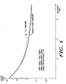
- the transform defined by v ij and z ij leads to an energy distribution among its coefficients that closely approximates that of the DCT which has almost-optimal energy compaction, i.e., the energy of the DCT coefficients is strongly concentrated in the first coefficients.
- the energy distribution of the v ij -z ij transform is compared to that of the DCT, for a first-order Gauss-Markov process with a correlation coefficient of 0.9, and a block size M of 16.
- the v ij -z ij transform can be efficiently implemented due to its close resemblance to the DCT. Since DCT direct and inverse transform operators are readily available (in hardware or software form), the v ij -z ij transform can make full use of those operators, with the addition of a few butterflies that implement the window.
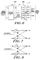
- Figs. 5 and 6 show butterfly diagrams across one block boundary of the signal I defined in the above-described one dimensional example.
- Fig. 5 shows the composite spatial operator processing performed by preprocessor 12 and block encoder 30
- Fig. 6 shows the composite spatial operator processing performed by block decoder 38 and postprocessor 16. While the butterfly diagrams of Figs. 5 and 6 show one implementation of the illustrative embodiment
- Figs. 7 and 8 illustrate an alternative implementation of one exemplary butterfly which may be used in place of the butterflies of Figs. 5 and 6.
- the weighted arrows on both sides of the block boundary are the same (i.e., h(1) in Fig. 7 and h(1) in Fig. 8), since the coefficients of the window functions are symmetrical across the block boundaries. In that way, the associated pairs of sample values which are symmetrically disposed about the boundary are combined.
- the input signal I may be expressed in terms of an overlapping succession of 1 x (M+2K) matrices of the coefficients of the function I.
- the preprocessor 12 in that case is a butterfly network modifying the first two and last two coefficients of each of the I matrices, as shown in Fig. 5.
- the direct transform element 30A is a matrix multiplying apparatus which generates the 1 x M matrix of coefficients for the signal T' (for application to the coefficient quantizer 30B) by multiplying the 1 x M T-matrix by the M x M DCT-matrix (effectively multiplying a 1 x (M+2K) I-matrix by the (M+2K) x M v ij -matrix).
- the signal T' may be conventionally processed by quantizer 30B and encoder/transmitter 32 to generate the signal E which is transmitted (via medium 34) to receiver/decoder 36.
- the receiver/encoder 36 conventionally decodes the received signal E and reconstructs the transform coefficients (signal D').
- Signal D' is then applied to element 38B.
- Element 38B is a matrix multiplying apparatus which multiplies 1 x M D'-matrix by the M x M IDCT-matrix to generate the 1 x M BP matrix.
- the butterfly network of postprocessor 16 modifies the first two and last two coefficients of the BP-matrix, as shown in Fig. 6, to generate the 1 x M I'-matrix.
- the BP signal is treated as if it was a 1 x (M+2k) signal which is operated on by the butterfly networks to combine two pixel overlapping regions of adjacent blocks in order to obtain the 1 x M signal.
- the coefficients of the V-matrix are the v ij coefficients described above and the coefficients of the Z matrix are the z ij coefficients described above.
- the present invention may also be implemented to remove blocking effects in two-dimensional functions, such as images, where blocking effects have posed significant problems in prior art signal processing applications.
- two-dimensional transforms are used. Such transforms may be readily implemented using the above-described one-dimensional embodiment, for example, by simply processing the rows and columns of each block with the one-dimensional transform in the manner illustrated in the flow chart of Fig. 9. That is, each row and each column of the input signal may be independently preprocessed and postprocessed as in the one-dimensional example. The resultant coefficiently correspond to the block effect-free output signal.
- Appendix A includes a listing of a program entitled "Codenew" which performs block coding of a two-dimensional image by using the present invention.
- the program is written in the PASCAL language, and utilizes the following hardware and supporting software: IBM Personal Computer with 2 disk drives, 512 kilobytes of RAM memory, and a DATACUBE IVG-128 image capture/display board, DOS operating system and TURBO PASCAL compiler.
- the program can be easily modified to support a different hardware configuration or translated into another high-level language, like FORTRAN or C.
- the sections of the program labeled "Pre-filtering" and "Post-filtering” implement the data intermixing butterflies, similar to those shown in Figs. 5 and 6. With this intermixing, the sample values of associated pairs of the input signal (symmetrically disposed about a block boundary) are linearly combined to obtain the modified sample values.
- the weighting coefficients for the various combinations for each block are symmetrical across that block. Moreover, the sum of the weighting coefficients for each sample in a block and the weighting coefficients for that sample value in adjacent blocks equals unity.
- the present invention is an improved method and system for block coding of images (or other signals), minimizing blocking effects.
- the method and system incorporate the following properties:
- the DCT and IDCT blocks in Figs. 5 and 6 may be replaced by any other block-processing operators, such as block filtering, and the butterflies corresponding to the w(i) and h(j) windows can be viewed as pre- and post-filters that intermix (or combine) the data across block boundaries in a way that blocking effects are effectively reduced.
- block filtering any other block-processing operators
- the butterflies corresponding to the w(i) and h(j) windows can be viewed as pre- and post-filters that intermix (or combine) the data across block boundaries in a way that blocking effects are effectively reduced.
- Such systems are applicable to any signal processing environment where the amount of data to be processed is large enough to justify block processing, as it is the case for images, speech, geophysics, radar, sonar and others.
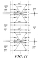
- Figs. 10 and 11 illustrate a more generalized embodiment of the invention in which K is greater than 2, with K data intermixing (or combining) butterflies being shown at the block boundaries for three blocks.
- the data across block boundaries may be intermixed to be performed by a more general linear operator than the butterflies depicted in Figs. 10 and 11, since those butterflies impose a somewhat restrictive way of processing the 2K data points that lie across a block boundary.
- a general 2K x 2K matrix could be used, although there might be an increase in computational overhead.
Landscapes
- Engineering & Computer Science (AREA)
- Multimedia (AREA)
- Signal Processing (AREA)
- Compression Or Coding Systems Of Tv Signals (AREA)
- Compression, Expansion, Code Conversion, And Decoders (AREA)
- Compression Of Band Width Or Redundancy In Fax (AREA)
- Complex Calculations (AREA)
- Image Processing (AREA)
- Error Detection And Correction (AREA)
Claims (11)
- Vorrichtung zum Verarbeiten, durch Reduzieren der Blockbildungseffekte, eines n-dimensionalen Digitalsignals, das zumindest zwei benachbarte M₁ x M₂ x ... x Mn Blöcke digitaler Abtastwerte enthält, wobei M₁, M₂,..., Mn ganze Zahlen sind, die jeweils einer der n Dimensionen zugeordnet sind, gekennzeichnet durch
eine Einrichtung zum Transformieren des Digitalsignals in Übereinstimmung mit einem ersten zusammengesetzten Raumoperator zum Erhalten eines ersten transformierten Signals, wobei der erste zusammengesetzte Raumoperator
einen ersten räumlichen Transformationsoperator mit M₁ x M₂ x ... x Mn Basisfunktionen umfaßt, wobei der erste räumliche Transformationsoperator ein Gebiet und einen Bereich über einen n-dimensionalen hohlen Block von (M₁ + 2K₁) x (M₂ + 2K₂) x...x (Mn + 2Kn) Blöcken der Abtastwerte des Digitalsignals bei Überlappung der Peripherie eines untergelegten M₁ x M₂ x...x Mn-Blocks der Abtastwerte besitzt, K₁, K₂, ..., Kn nicht-negative ganze Zahlen sind und zumindest einer der Werte von K₁, K₂, .... Kn nicht Null ist, und
einen ersten Blockverarbeitungsoperator, der M₁ x M₂ x ... x Mn Blöcken zugeordnet ist, welcher Blockverarbeitungsoperator M₁ x M₂ x ... x Mn Basisfunktionen besitzt, wobei der erste Blockverarbeitungsoperator ein Gebiet und einen Bereich über einen Block von M₁ x M₂ x...x Mn Blöcken der von dem ersten räumlichen Transformationsoperator erzeugten Signalwerte aufweist und das erste transformierte Signal ein Blockverarbeitungssignal ist. - Vorrichtung nach Anspruch 1, ferner gekennzeichnet durch
eine Einrichtung zum Transformieren des ersten transformierten Signals in Übereinstimmung mit einem zweiten zusammengesetzten Raumoperator zum Erhalten eines transformierten Ausgangssignals, wobei der zweite zusammengesetzte Raumoperator einen zweiten Blockverarbeitungsoperator mit M₁ x M₂ x...xMn Basisfunktionen aufweist. - Vorrichtung nach Anspruch 2, bei der das transformierte Ausgangssignal dem Digitalsignal entspricht,
der zweite zusammengesetzte Raumoperator invers zum ersten zusammengesetzten Raumoperators ist und
der erste und der zweite zusammengesetzte Raumoperator nicht-orthogonal sind. - Vorrichtung nach Anspruch 2, mit einer Einrichtung, die nach der Einrichtung zum Transformieren in Übereinstimmung mit dem ersten zusammengesetzten Raumoperator und vor der Einrichtung zum Transformieren in Übereinstimmung mit dem zweiten zusammengesetzten Raumoperator wirksam ist, um
das Blockverarbeitungssignal zur Erzielung eines für eine Übertragung über ein Kommunikationsmedium geeigneten kodierten Signals zu kodieren,
das kodierte Signal über das Medium zu übertragen,
das kodierte Signal zu empfangen und das empfangene kodierte Signal zu dekodieren, um erneut das Blockverarbeitungssignal zu erhalten. - Vorrichtung nach Anspruch 1, wobei der erste Blockverarbeitungsoperator aus einem diskreten Cosinustransformations(DCT)-Operator besteht.
- Vorrichtung nach Anspruch 2 oder Anspruch 3, bei der der erste Blockverarbeitungsoperator aus einem diskreten Cosinustransformations(DCT)-Operator und der zweite zusammengesetzte Raumoperator aus einem inversen DCT-Operator besteht.
- Vorrichtung nach Anspruch 1, bei der der erste zusammengesetzte Raumoperator die Form des Produkts einer Fensterfunktion und einen modifizierten diskreten Cosinustransformations(DCT)-Operator besitzt,
wobei der modifizierte DCT-Operator gekennzeichnet ist durch M₁ x M₂ x ... x Mn Basisfunktionen über (M₁ + 2K₁) x (M₂ + 2K₂) x ... x (Mn + 2Kn) Blöcke von Abtastwerten des Digitalsignals und
wobei die Fensterfunktion eine n-dimensionale Sequenz ist und wobei die Fensterfunktion symmetrisch in jeder der n Dimensionen ist und für jeden Abtastwert in einem Block die Summe der Fensterfunktion für diesen Abtastwert in diesem Block und der Fensterfunktionen für diesen Abtastwert in allen an diesen Block angrenzenden Blöcken ein vorbestimmter Wert ist. - Vorrichtung nach Anspruch 1, bei der die Einrichtung zum Transformieren in Übereinstimmung mit dem ersten räumlichen Transformationsoperator eine Einrichtung zum Verändern der Abtastwerte durch Ersetzen ausgewählter Werte der Abtastwerte in den Blöcken durch abgeänderte Abtastwerte umfaßt, wobei die abgeänderten Abtastwerte gleich sind der Kombination von Paaren assoziierter Abtastwerte, die symmetrisch um die Grenzen zwischen benachbarten Blöcken des Digitalsignals angeordnet sind.
- Vorrichtung nach Anspruch 8, bei der die Veränderungseinrichtung eine Einrichtung zum Erzeugen gewichteter Linearkombinationen der Paare von Abtastwerten aufweist.
- Vorrichtung nach Anspruch 8 oder Anspruch 9, bei der die Verteilung der gewichteten Koeffizienten der Kombinationen für jedes der Paare in einem Block symmetrisch über diesen Block verläuft.
- Vorrichtung nach Anspruch 9 oder Anspruch 10, bei der für jeden Abtastwert in einem Block die Summe der gewichteten Koeffizienten für diesen Abtastwert in diesem Block und der gewichteten Koeffizienten für diesen Abtastwert in allen an diesen Block angrenzenden Blöcken ein vorbestimmter Wert ist.
Priority Applications (1)
| Application Number | Priority Date | Filing Date | Title |
|---|---|---|---|
| AT86904499T ATE75333T1 (de) | 1985-06-03 | 1986-06-03 | Vorrichtung zur anpassung eines digitalsignalverarbeitungssystems fuer blockverarbeitung mit minimalen blockartefakten. |
Applications Claiming Priority (2)
| Application Number | Priority Date | Filing Date | Title |
|---|---|---|---|
| US06/740,806 US4754492A (en) | 1985-06-03 | 1985-06-03 | Method and system for adapting a digitized signal processing system for block processing with minimal blocking artifacts |
| US740806 | 1985-06-03 |
Publications (3)
| Publication Number | Publication Date |
|---|---|
| EP0224583A1 EP0224583A1 (de) | 1987-06-10 |
| EP0224583A4 EP0224583A4 (de) | 1988-09-07 |
| EP0224583B1 true EP0224583B1 (de) | 1992-04-22 |
Family
ID=24978159
Family Applications (1)
| Application Number | Title | Priority Date | Filing Date |
|---|---|---|---|
| EP86904499A Expired EP0224583B1 (de) | 1985-06-03 | 1986-06-03 | Vorrichtung zur anpassung eines digitalsignalverarbeitungssystems für blockverarbeitung mit minimalen blockartefakten |
Country Status (7)
| Country | Link |
|---|---|
| US (1) | US4754492A (de) |
| EP (1) | EP0224583B1 (de) |
| JP (1) | JP2651908B2 (de) |
| AT (1) | ATE75333T1 (de) |
| CA (1) | CA1255391A (de) |
| DE (1) | DE3684996D1 (de) |
| WO (1) | WO1986007479A1 (de) |
Families Citing this family (101)
| Publication number | Priority date | Publication date | Assignee | Title |
|---|---|---|---|---|
| US5496927A (en) * | 1985-02-04 | 1996-03-05 | Merrell Pharmaceuticals Inc. | Peptidase inhibitors |
| BE904101A (nl) * | 1986-01-24 | 1986-07-24 | Bell Telephone Mfg Cy | Beeldverwerkingssysteem en daarin toegepaste fazevergrendelingslus. |
| GB8621994D0 (en) * | 1986-09-12 | 1986-10-22 | Crosfield Electronics Ltd | Image processing |
| US5045853A (en) * | 1987-06-17 | 1991-09-03 | Intel Corporation | Method and apparatus for statistically encoding digital data |
| GB8800503D0 (en) * | 1988-01-11 | 1988-02-10 | Crosfield Electronics Ltd | Apparatus for generating two-dimensional coloured display |
| JP2844695B2 (ja) * | 1989-07-19 | 1999-01-06 | ソニー株式会社 | 信号符号化装置 |
| US5121216A (en) * | 1989-07-19 | 1992-06-09 | Bell Communications Research | Adaptive transform coding of still images |
| US5267051A (en) * | 1989-12-22 | 1993-11-30 | Eastman Kodak Company | High speed compression of imagery data |
| US5502789A (en) * | 1990-03-07 | 1996-03-26 | Sony Corporation | Apparatus for encoding digital data with reduction of perceptible noise |
| ATE154485T1 (de) * | 1990-03-15 | 1997-06-15 | Thomson Multimedia Sa | Digitale bildverarbeitung mit filterung der blockkanten |
| US5416854A (en) | 1990-07-31 | 1995-05-16 | Fujitsu Limited | Image data processing method and apparatus |
| US5875266A (en) * | 1990-07-31 | 1999-02-23 | Fujitsu Limited | Image data processing a method and apparatus |
| US5020121A (en) * | 1990-08-16 | 1991-05-28 | Hewlett-Packard Company | Neighborhood block prediction bit compression |
| GB2247132A (en) * | 1990-08-17 | 1992-02-19 | Sony Broadcast & Communication | Digital video data compression |
| EP0487282B1 (de) * | 1990-11-19 | 2000-03-01 | Canon Kabushiki Kaisha | Bildverarbeitungsgerät und -Verfahren |
| US5172227A (en) * | 1990-12-10 | 1992-12-15 | Eastman Kodak Company | Image compression with color interpolation for a single sensor image system |
| US5218650A (en) * | 1991-01-02 | 1993-06-08 | Ricoh Corporation | Quantization method for use in image compression |
| US5625714A (en) * | 1991-01-10 | 1997-04-29 | Olympus Optical Co., Ltd. | Image signal decoding device capable of removing block distortion with simple structure |
| GB2253318B (en) * | 1991-02-27 | 1994-07-20 | Stc Plc | Image processing |
| JP3297445B2 (ja) * | 1991-04-23 | 2002-07-02 | キヤノン株式会社 | 出力方法及び装置 |
| US5742345A (en) * | 1991-07-05 | 1998-04-21 | Samsung Electronics Co., Ltd. | System for transmitting and receiving video signals using interpolation of adaptive factor |
| US5454051A (en) * | 1991-08-05 | 1995-09-26 | Eastman Kodak Company | Method of reducing block artifacts created by block transform compression algorithms |
| US5787207A (en) * | 1991-12-30 | 1998-07-28 | Golin; Stuart J. | Method and apparatus for minimizing blockiness in reconstructed images |
| JPH05219385A (ja) * | 1992-02-07 | 1993-08-27 | Hudson Soft Co Ltd | 画像圧縮・伸張方法および装置 |
| US6205259B1 (en) * | 1992-04-09 | 2001-03-20 | Olympus Optical Co., Ltd. | Image processing apparatus |
| US5519503A (en) * | 1992-04-13 | 1996-05-21 | Sony Corporation | Picture reproducing apparatus |
| US5367385A (en) * | 1992-05-07 | 1994-11-22 | Picturetel Corporation | Method and apparatus for processing block coded image data to reduce boundary artifacts between adjacent image blocks |
| KR0148130B1 (ko) * | 1992-05-18 | 1998-09-15 | 강진구 | 블럭킹아티팩트를 억제시키는 부호화/복호화 방법 및 그 장치 |
| JP3165296B2 (ja) * | 1992-12-25 | 2001-05-14 | 三菱電機株式会社 | フレーム間符号化処理方式及びフレーム間符号化処理方法及び符号化制御方式 |
| JPH06327002A (ja) * | 1993-05-11 | 1994-11-25 | Olympus Optical Co Ltd | 動画像符号化装置 |
| KR970009302B1 (en) * | 1993-08-17 | 1997-06-10 | Lg Electronics Inc | Block effect reducing apparatus for hdtv |
| US5420942A (en) * | 1993-09-21 | 1995-05-30 | Levit; Itzhak | Methods and devices for self-correcting video compression |
| JP3195142B2 (ja) * | 1993-10-29 | 2001-08-06 | キヤノン株式会社 | 画像処理方法及び装置 |
| US5473384A (en) * | 1993-12-16 | 1995-12-05 | At&T Corp. | Method of and system for enhancing distorted graphical information |
| US5742346A (en) * | 1994-08-09 | 1998-04-21 | Picture Tel Corporation | Spatially adaptive blur filter |
| US6088130A (en) * | 1994-09-27 | 2000-07-11 | Canon Kabushiki Kaisha | Image processing apparatus and method |
| JP3686695B2 (ja) * | 1994-10-20 | 2005-08-24 | オリンパス株式会社 | 画像処理装置 |
| US5802218A (en) * | 1994-11-04 | 1998-09-01 | Motorola, Inc. | Method, post-processing filter, and video compression system for suppressing mosquito and blocking atrifacts |
| US5629778A (en) * | 1995-05-15 | 1997-05-13 | Polaroid Corporation | Method and apparatus for reduction of image data compression noise |
| US5751861A (en) * | 1995-06-30 | 1998-05-12 | Intel Corporation | Reducing residual artifacts in video coding schemes with integer motion compensation |
| FR2737931B1 (fr) * | 1995-08-17 | 1998-10-02 | Siemens Ag | Procede destine au traitement de blocs d'images decodes d'un procede de codage d'images a base de blocs |
| US5774597A (en) * | 1995-09-05 | 1998-06-30 | Ge Medical Systems, Inc. | Image compression and decompression using overlapped cosine transforms |
| GB2305798B (en) * | 1995-09-28 | 1999-10-20 | Sony Uk Ltd | Spatial frequency-domain video signal processing |
| US5995670A (en) * | 1995-10-05 | 1999-11-30 | Microsoft Corporation | Simplified chain encoding |
| US5787203A (en) * | 1996-01-19 | 1998-07-28 | Microsoft Corporation | Method and system for filtering compressed video images |
| US5799113A (en) * | 1996-01-19 | 1998-08-25 | Microsoft Corporation | Method for expanding contracted video images |
| US5764814A (en) * | 1996-03-22 | 1998-06-09 | Microsoft Corporation | Representation and encoding of general arbitrary shapes |
| US5982438A (en) * | 1996-03-22 | 1999-11-09 | Microsoft Corporation | Overlapped motion compensation for object coding |
| US5778098A (en) * | 1996-03-22 | 1998-07-07 | Microsoft Corporation | Sprite coding |
| DE19626985C1 (de) * | 1996-07-04 | 1998-01-02 | Siemens Ag | Verfahren und Anordnung zur Reduktion von Codierungsartefakten von blockbasierten Bildcodierungsverfahren und objektbasierten Bildcodierungsverfahren |
| US6075875A (en) * | 1996-09-30 | 2000-06-13 | Microsoft Corporation | Segmentation of image features using hierarchical analysis of multi-valued image data and weighted averaging of segmentation results |
| US6094453A (en) * | 1996-10-11 | 2000-07-25 | Digital Accelerator Corporation | Digital data compression with quad-tree coding of header file |
| US5748789A (en) * | 1996-10-31 | 1998-05-05 | Microsoft Corporation | Transparent block skipping in object-based video coding systems |
| US6052490A (en) * | 1997-02-14 | 2000-04-18 | At&T Corp. | Video coder employing pixel transposition |
| KR100251549B1 (ko) * | 1997-02-28 | 2000-04-15 | 구자홍 | 블로킹 효과 제거 기능을 갖는 디지탈 영상 복호화 장치 |
| AU727601B2 (en) * | 1997-05-07 | 2000-12-14 | Landmark Graphics Corporation | Method for data compression |
| FI103003B (fi) * | 1997-06-13 | 1999-03-31 | Nokia Corp | Suodatusmenetelmä, suodatin ja kannettava päätelaite |
| KR100281099B1 (ko) * | 1997-07-30 | 2001-04-02 | 구자홍 | 동영상의부호화에따른블록화현상제거방법 |
| IL122258A (en) * | 1997-11-20 | 2002-08-14 | Israel Aircraft Ind Ltd | Method and system for determining temperature and/or emissivity function of objects by remote sensing |
| US6400831B2 (en) | 1998-04-02 | 2002-06-04 | Microsoft Corporation | Semantic video object segmentation and tracking |
| US6115689A (en) * | 1998-05-27 | 2000-09-05 | Microsoft Corporation | Scalable audio coder and decoder |
| US6029126A (en) * | 1998-06-30 | 2000-02-22 | Microsoft Corporation | Scalable audio coder and decoder |
| US6285801B1 (en) * | 1998-05-29 | 2001-09-04 | Stmicroelectronics, Inc. | Non-linear adaptive image filter for filtering noise such as blocking artifacts |
| US6249549B1 (en) * | 1998-10-09 | 2001-06-19 | Matsushita Electric Industrial Co., Ltd. | Down conversion system using a pre-decimation filter |
| JP3623679B2 (ja) * | 1999-01-06 | 2005-02-23 | 日本電気株式会社 | 動画像符号化装置 |
| FR2790173A1 (fr) * | 1999-02-24 | 2000-08-25 | Canon Kk | Dispositif et procede de transformation de signal numerique |
| US6577766B1 (en) * | 1999-11-10 | 2003-06-10 | Logitech, Inc. | Method and apparatus for motion detection in the discrete cosine transform domain |
| EP1310097B1 (de) | 2000-08-15 | 2019-07-31 | Microsoft Technology Licensing, LLC | Verfahren, systeme und datenstrukturen zur zeitcodierung von media-mustern |
| US6822675B2 (en) * | 2001-07-03 | 2004-11-23 | Koninklijke Philips Electronics N.V. | Method of measuring digital video quality |
| EP1421579B1 (de) * | 2001-08-21 | 2006-04-05 | Koninklijke Philips Electronics N.V. | Audio kodierer mit unregelmässiger filterbank |
| US7120297B2 (en) * | 2002-04-25 | 2006-10-10 | Microsoft Corporation | Segmented layered image system |
| US7024039B2 (en) * | 2002-04-25 | 2006-04-04 | Microsoft Corporation | Block retouching |
| US7263227B2 (en) * | 2002-04-25 | 2007-08-28 | Microsoft Corporation | Activity detector |
| US7164797B2 (en) * | 2002-04-25 | 2007-01-16 | Microsoft Corporation | Clustering |
| US7043079B2 (en) * | 2002-04-25 | 2006-05-09 | Microsoft Corporation | “Don't care” pixel interpolation |
| US7392472B2 (en) * | 2002-04-25 | 2008-06-24 | Microsoft Corporation | Layout analysis |
| US7110596B2 (en) * | 2002-04-25 | 2006-09-19 | Microsoft Corporation | System and method facilitating document image compression utilizing a mask |
| US6831868B2 (en) * | 2002-12-05 | 2004-12-14 | Intel Corporation | Byte aligned redundancy for memory array |
| US7471726B2 (en) * | 2003-07-15 | 2008-12-30 | Microsoft Corporation | Spatial-domain lapped transform in digital media compression |
| US7724827B2 (en) | 2003-09-07 | 2010-05-25 | Microsoft Corporation | Multi-layer run level encoding and decoding |
| US7369709B2 (en) * | 2003-09-07 | 2008-05-06 | Microsoft Corporation | Conditional lapped transform |
| US7643688B2 (en) * | 2003-10-10 | 2010-01-05 | Hewlett-Packard Development Company, L.P. | Reducing artifacts in compressed images |
| US7570818B2 (en) * | 2003-10-17 | 2009-08-04 | Hewlett-Packard Development Company, L.P. | Method for deblocking and transcoding a media stream |
| US7539870B2 (en) * | 2004-02-10 | 2009-05-26 | Microsoft Corporation | Media watermarking by biasing randomized statistics |
| US20050226503A1 (en) * | 2004-04-07 | 2005-10-13 | Bailey James R | Scanned image content analysis |
| US7545988B2 (en) * | 2004-08-09 | 2009-06-09 | George William Meeker | Image blocking artifact reduction via transform pair |
| US7471850B2 (en) * | 2004-12-17 | 2008-12-30 | Microsoft Corporation | Reversible transform for lossy and lossless 2-D data compression |
| US7305139B2 (en) * | 2004-12-17 | 2007-12-04 | Microsoft Corporation | Reversible 2-dimensional pre-/post-filtering for lapped biorthogonal transform |
| US7428342B2 (en) * | 2004-12-17 | 2008-09-23 | Microsoft Corporation | Reversible overlap operator for efficient lossless data compression |
| JP2006277903A (ja) * | 2005-03-30 | 2006-10-12 | Hitachi Global Storage Technologies Netherlands Bv | 符号化装置、及び復号装置 |
| US8036274B2 (en) * | 2005-08-12 | 2011-10-11 | Microsoft Corporation | SIMD lapped transform-based digital media encoding/decoding |
| JP4868599B2 (ja) * | 2007-10-18 | 2012-02-01 | 株式会社メガチップス | 周波数変換器、階層符号器、および、階層復号器 |
| US8369638B2 (en) | 2008-05-27 | 2013-02-05 | Microsoft Corporation | Reducing DC leakage in HD photo transform |
| US8447591B2 (en) * | 2008-05-30 | 2013-05-21 | Microsoft Corporation | Factorization of overlapping tranforms into two block transforms |
| US8275209B2 (en) * | 2008-10-10 | 2012-09-25 | Microsoft Corporation | Reduced DC gain mismatch and DC leakage in overlap transform processing |
| US8428959B2 (en) * | 2010-01-29 | 2013-04-23 | Polycom, Inc. | Audio packet loss concealment by transform interpolation |
| US9525884B2 (en) * | 2010-11-02 | 2016-12-20 | Hfi Innovation Inc. | Method and apparatus of slice boundary filtering for high efficiency video coding |
| WO2015078420A1 (en) * | 2013-11-29 | 2015-06-04 | Mediatek Inc. | Methods and apparatus for intra picture block copy in video compression |
| US10110926B2 (en) | 2015-10-15 | 2018-10-23 | Cisco Technology, Inc. | Efficient loop filter for video codec |
| CN107945101B (zh) * | 2016-10-13 | 2021-01-29 | 华为技术有限公司 | 图像处理方法和装置 |
| CN112543345B (zh) * | 2020-12-02 | 2023-01-06 | 深圳创维新世界科技有限公司 | 图像处理方法、发送端、接收端以及计算机可读存储介质 |
Family Cites Families (15)
| Publication number | Priority date | Publication date | Assignee | Title |
|---|---|---|---|---|
| US4261048A (en) | 1975-12-25 | 1981-04-07 | Citizen Watch Company Limited | Analog quartz timepiece |
| US4224678A (en) * | 1976-04-05 | 1980-09-23 | Northrop Corporation | Method and apparatus for implementing a processor based on the rationalized Haar transform for the purpose of real time compression of video data |
| US4027257A (en) * | 1976-06-01 | 1977-05-31 | Xerox Corporation | Frequency domain automatic equalizer having logic circuitry |
| US4205341A (en) * | 1978-01-24 | 1980-05-27 | Nippon Telegraph And Telephone Public Corporation | Picture signal coding apparatus |
| US4302775A (en) * | 1978-12-15 | 1981-11-24 | Compression Labs, Inc. | Digital video compression system and methods utilizing scene adaptive coding with rate buffer feedback |
| US4394774A (en) * | 1978-12-15 | 1983-07-19 | Compression Labs, Inc. | Digital video compression system and methods utilizing scene adaptive coding with rate buffer feedback |
| US4245248A (en) * | 1979-04-04 | 1981-01-13 | Bell Telephone Laboratories, Incorporated | Motion estimation and encoding of video signals in the transform domain |
| US4261018A (en) * | 1979-06-18 | 1981-04-07 | Bell Telephone Laboratories, Incorporated | Progressive image transmission |
| US4261043A (en) * | 1979-08-24 | 1981-04-07 | Northrop Corporation | Coefficient extrapolator for the Haar, Walsh, and Hadamard domains |
| US4288858A (en) * | 1979-10-01 | 1981-09-08 | General Electric Company | Inverse two-dimensional transform processor |
| US4281344A (en) * | 1980-05-02 | 1981-07-28 | Bell Telephone Laboratories, Incorporated | Video interframe transform coding technique |
| US4447886A (en) * | 1981-07-31 | 1984-05-08 | Meeker G William | Triangle and pyramid signal transforms and apparatus |
| US4602286A (en) * | 1982-01-15 | 1986-07-22 | Quantel Limited | Video processing for composite images |
| FR2527033A1 (fr) * | 1982-05-17 | 1983-11-18 | Telediffusion Fse | Systeme d'incrustation d'images en television en couleurs |
| US4616262A (en) * | 1983-11-14 | 1986-10-07 | Dainippon Ink And Chemicals, Incorporated | Method and apparatus for forming a combined image signal |
-
1985
- 1985-06-03 US US06/740,806 patent/US4754492A/en not_active Expired - Lifetime
-
1986
- 1986-06-03 CA CA000510748A patent/CA1255391A/en not_active Expired
- 1986-06-03 WO PCT/US1986/001212 patent/WO1986007479A1/en not_active Ceased
- 1986-06-03 AT AT86904499T patent/ATE75333T1/de not_active IP Right Cessation
- 1986-06-03 JP JP61503609A patent/JP2651908B2/ja not_active Expired - Fee Related
- 1986-06-03 DE DE8686904499T patent/DE3684996D1/de not_active Expired - Lifetime
- 1986-06-03 EP EP86904499A patent/EP0224583B1/de not_active Expired
Also Published As
| Publication number | Publication date |
|---|---|
| ATE75333T1 (de) | 1992-05-15 |
| CA1255391A (en) | 1989-06-06 |
| WO1986007479A1 (en) | 1986-12-18 |
| EP0224583A1 (de) | 1987-06-10 |
| EP0224583A4 (de) | 1988-09-07 |
| US4754492A (en) | 1988-06-28 |
| DE3684996D1 (de) | 1992-05-27 |
| JP2651908B2 (ja) | 1997-09-10 |
| JPS63500070A (ja) | 1988-01-07 |
Similar Documents
| Publication | Publication Date | Title |
|---|---|---|
| EP0224583B1 (de) | Vorrichtung zur anpassung eines digitalsignalverarbeitungssystems für blockverarbeitung mit minimalen blockartefakten | |
| US5629778A (en) | Method and apparatus for reduction of image data compression noise | |
| EP0857392B1 (de) | Waveletbaum-bildcoder mit überlappenden bildblöcken | |
| US5454051A (en) | Method of reducing block artifacts created by block transform compression algorithms | |
| US5289548A (en) | Compression and reconstruction of radiological images | |
| US4703349A (en) | Method and apparatus for multi-dimensional signal processing using a Short-Space Fourier transform | |
| CA2306372C (en) | Lossless region of interest coding | |
| US5929912A (en) | Image coding/decoding apparatus | |
| US6721460B1 (en) | Video coder employing pixel transposition | |
| US5268961A (en) | Error control apparatus for a digital video signal processing system | |
| CA2275320A1 (en) | Improved estimator for recovering high frequency components from compressed image data | |
| EP0987901A2 (de) | Technik für Videokommunikation mit adaptivem Filterungsystem | |
| US5426673A (en) | Discrete cosine transform-based image coding and decoding method | |
| Schiller | Overlapping block transform for image coding preserving equal number of samples and coefficients | |
| KR100349518B1 (ko) | 인간 시각 시스템의 특성을 반영한 퍼지 논리를 적용한이산 웨이브렛 변환을 이용한 영상 압축 방법 및 장치 | |
| Wu et al. | Enhancement of transform coding by nonlinear interpolation | |
| Eddins et al. | A three-source multirate model for image compression | |
| JPH0779350A (ja) | 画像データ圧縮処理方法および画像データ再構成方法 | |
| Wilson et al. | Image coding using a predictor controlled by image content | |
| Prost et al. | Regularized subband coding scheme | |
| Yu et al. | New approach to image coding using 1-D subband filtering | |
| Hammer et al. | Image coding by vector quantization of M-Hadamard transform coefficients | |
| Venkatraraman et al. | Low-bit-rate compression using recursive block coding techniques | |
| Florêncio et al. | Can the sample being transmitted be used to refine its own PDF estimate? | |
| Choy et al. | Regularized restoration of vector quantisation compressed images |
Legal Events
| Date | Code | Title | Description |
|---|---|---|---|
| PUAI | Public reference made under article 153(3) epc to a published international application that has entered the european phase |
Free format text: ORIGINAL CODE: 0009012 |
|
| AK | Designated contracting states |
Kind code of ref document: A1 Designated state(s): AT BE CH DE FR GB IT LI LU NL SE |
|
| 17P | Request for examination filed |
Effective date: 19870527 |
|
| A4 | Supplementary search report drawn up and despatched |
Effective date: 19880907 |
|
| RIN1 | Information on inventor provided before grant (corrected) |
Inventor name: MALVAR, HENRIQUE, S. |
|
| RIN1 | Information on inventor provided before grant (corrected) |
Inventor name: MALVAR, HENRIQUE, S. |
|
| 17Q | First examination report despatched |
Effective date: 19900615 |
|
| GRAA | (expected) grant |
Free format text: ORIGINAL CODE: 0009210 |
|
| AK | Designated contracting states |
Kind code of ref document: B1 Designated state(s): AT BE CH DE FR GB IT LI LU NL SE |
|
| PG25 | Lapsed in a contracting state [announced via postgrant information from national office to epo] |
Ref country code: IT Free format text: LAPSE BECAUSE OF FAILURE TO SUBMIT A TRANSLATION OF THE DESCRIPTION OR TO PAY THE FEE WITHIN THE PRE;WARNING: LAPSES OF ITALIAN PATENTS WITH EFFECTIVE DATE BEFORE 2007 MAY HAVE OCCURRED AT ANY TIME BEFORE 2007. THE CORRECT EFFECTIVE DATE MAY BE DIFFERENT FROM THE ONE RECORDED.SCRIBED TIME-LIMIT Effective date: 19920422 Ref country code: BE Effective date: 19920422 Ref country code: AT Effective date: 19920422 Ref country code: SE Effective date: 19920422 Ref country code: NL Effective date: 19920422 |
|
| REF | Corresponds to: |
Ref document number: 75333 Country of ref document: AT Date of ref document: 19920515 Kind code of ref document: T |
|
| REF | Corresponds to: |
Ref document number: 3684996 Country of ref document: DE Date of ref document: 19920527 |
|
| ET | Fr: translation filed | ||
| PG25 | Lapsed in a contracting state [announced via postgrant information from national office to epo] |
Ref country code: LU Free format text: LAPSE BECAUSE OF NON-PAYMENT OF DUE FEES Effective date: 19920630 |
|
| NLV1 | Nl: lapsed or annulled due to failure to fulfill the requirements of art. 29p and 29m of the patents act | ||
| PLBE | No opposition filed within time limit |
Free format text: ORIGINAL CODE: 0009261 |
|
| STAA | Information on the status of an ep patent application or granted ep patent |
Free format text: STATUS: NO OPPOSITION FILED WITHIN TIME LIMIT |
|
| 26N | No opposition filed | ||
| PGFP | Annual fee paid to national office [announced via postgrant information from national office to epo] |
Ref country code: CH Payment date: 19990525 Year of fee payment: 14 |
|
| PG25 | Lapsed in a contracting state [announced via postgrant information from national office to epo] |
Ref country code: CH Free format text: LAPSE BECAUSE OF NON-PAYMENT OF DUE FEES Effective date: 20000630 Ref country code: LI Free format text: LAPSE BECAUSE OF NON-PAYMENT OF DUE FEES Effective date: 20000630 |
|
| REG | Reference to a national code |
Ref country code: CH Ref legal event code: PL |
|
| REG | Reference to a national code |
Ref country code: GB Ref legal event code: IF02 |
|
| PGFP | Annual fee paid to national office [announced via postgrant information from national office to epo] |
Ref country code: FR Payment date: 20020610 Year of fee payment: 17 |
|
| PG25 | Lapsed in a contracting state [announced via postgrant information from national office to epo] |
Ref country code: FR Free format text: LAPSE BECAUSE OF NON-PAYMENT OF DUE FEES Effective date: 20040227 |
|
| REG | Reference to a national code |
Ref country code: FR Ref legal event code: ST |
|
| PGFP | Annual fee paid to national office [announced via postgrant information from national office to epo] |
Ref country code: GB Payment date: 20040505 Year of fee payment: 19 |
|
| PGFP | Annual fee paid to national office [announced via postgrant information from national office to epo] |
Ref country code: DE Payment date: 20040630 Year of fee payment: 19 |
|
| PG25 | Lapsed in a contracting state [announced via postgrant information from national office to epo] |
Ref country code: GB Free format text: LAPSE BECAUSE OF NON-PAYMENT OF DUE FEES Effective date: 20050603 |
|
| PG25 | Lapsed in a contracting state [announced via postgrant information from national office to epo] |
Ref country code: DE Free format text: LAPSE BECAUSE OF NON-PAYMENT OF DUE FEES Effective date: 20060103 |
|
| GBPC | Gb: european patent ceased through non-payment of renewal fee |
Effective date: 20050603 |