EP0223874B1 - Giessform für Zylinderblöcke von Verbrennungsmotoren - Google Patents
Giessform für Zylinderblöcke von Verbrennungsmotoren Download PDFInfo
- Publication number
- EP0223874B1 EP0223874B1 EP85114970A EP85114970A EP0223874B1 EP 0223874 B1 EP0223874 B1 EP 0223874B1 EP 85114970 A EP85114970 A EP 85114970A EP 85114970 A EP85114970 A EP 85114970A EP 0223874 B1 EP0223874 B1 EP 0223874B1
- Authority
- EP
- European Patent Office
- Prior art keywords
- mould
- cylinder block
- box mould
- lower box
- cylinder
- Prior art date
- Legal status (The legal status is an assumption and is not a legal conclusion. Google has not performed a legal analysis and makes no representation as to the accuracy of the status listed.)
- Expired
Links
Images



Classifications
-
- B—PERFORMING OPERATIONS; TRANSPORTING
- B22—CASTING; POWDER METALLURGY
- B22C—FOUNDRY MOULDING
- B22C9/00—Moulds or cores; Moulding processes
Definitions
- the invention relates to a casting mold for cylinder blocks of internal combustion engines with a lower case shape, an upper case shape, a water jacket core and possibly a head plate bore core, with a dividing line between the mold halves in the outer region of the mold halves extending horizontally.
- Such cylinder blocks are usually cast from gray cast iron or aluminum.
- the outer contours of gray cast iron blocks are formed by compressed molding sand (green sand, consisting of quartz sand, bentonite, coal dust and water).
- the inner contours of the cylinder blocks are formed by suitable cores, the cores being produced from quartz sand or other sands with cold and / or hot curing binder systems (resin and hardener).
- the cores used in such casting processes are very expensive.
- the cylinder blocks are cast standing on the base plate, using the cores listed above.
- the two mold halves, which are arranged laterally here, are moved perpendicular to the axis of the cylinder bores.
- the invention avoids these disadvantages. It is based on the task of proposing a casting mold of the type mentioned at the outset, in the use of which a part of the relatively expensive cores can be replaced by shaped contours. Nevertheless, the cylinder blocks cast with the casting mold according to the invention are to be distinguished by narrow tolerances and an overall reduced material consumption combined with a reduced manufacturing time.
- the invention is characterized in that the lower box shape and the upper box shape are designed and arranged such that the cylinder block is cast upright and that the lower box shape and the upper box shape can be demolded in the axial direction of the cylinder block, the lower box shape also the interior of the crankcase.
- the crankcase area can now be produced in green form.
- the distance and the width dimension of the bearing blocks of the cylinder block can be manufactured with greater accuracy. It is also possible to work with lower processing allowances.
- the housing wall thickness can be considerably reduced in nominal size and within its tolerance range compared to cylinder blocks that are conventionally cast.
- the water jacket core no longer needs to be supported by core supports. He also receives no deformation during the casting process, as is the case with the known casting mold with the cylinder block arranged horizontally, because the water jacket core stands upright.
- a circular outer cylinder diameter is made possible. This can be reduced to the minimum construction size. Overall, the new casting mold enables tighter manufacturing tolerances to be achieved, combined with tangible weight savings.
- the outer contour of the cylinder block and its crank chamber area can be formed without undercuts, which then enables demolding in the axial direction without further ado.
- undercuts are present, for example for construction reasons, separate cores are used in the undercuts, which then allow the upper box shape and lower box shape to be demolded axially.
- the horizontal outer area of the dividing line between the upper box shape and the lower box shape extends in the area of the base plate of the cylinder block. This completely eliminates the influence of fluctuations in the distance between the top box shape and the bottom box shape.
- the cylinder block in question is provided on the footplate with an outwardly facing flange at the free end of the crankcase wall, which serves as a connection surface to the oil pan.
- the arrangement of the horizontal dividing line between the two forms can be said that this can of course also continue above the base plate of the cylinder block, provided that the principle of demoldability in the axial direction is maintained, and if one does not place such high value on eliminating those disadvantages that result from the inevitably existing fluctuations in distance between the two mold halves .
- the mold according to the invention is generally suitable for cylinder blocks of internal combustion engines, namely both for passenger cars and for trucks, including ship propulsion systems, etc.
- FIGS. 1 and 2 The invention is explained in more detail below on the basis of an exemplary embodiment from which further important features result. To illustrate the advantages of the invention, the two known casting molds already explained above are shown in FIGS. 1 and 2.
- the known casting mold shown in FIG. 1 has a lower box shape 1, an upper box shape 2, a crankcase core 3, a head plate bore core 4 and a water jacket core 5.
- a dividing line 6 between the mold halves 1, 2 runs horizontally and coincides with the longitudinal axis of the cylinder block 7 to be cast.
- the outer contour 8 of the cylinder block has projections in the axial direction, so that demolding in the axial direction would not be possible.
- the two mold halves 1, 2 are therefore demolded in the radial, perpendicular direction, i.e. in the direction of arrow 9.
- FIG. 2 The likewise known casting mold shown in FIG. 2 is fundamentally constructed like that according to FIG. 11, the only difference being that the cylinder block is cast standing upward from FIG. Also in Fig. 2, the two mold halves 1, 2 in the radial direction, i.e. in the direction of arrow 9, demolded.
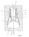
- FIG. 3 has a lower case shape 11, an upper case shape 12, a top plate bore core 13 and a water jacket core 14. It can be seen that the lower case shape also takes on the function of the otherwise existing crankcase core.
- a dividing line 15 between the mold halves 11, 12 runs horizontally in the outer region, specifically in the plane of the base plate surface of the cylinder block 16. Then inwards it follows the shape of the crank chamber region.
- the outer contour 17 of the cylinder block has no undercuts, so that the mold halves 11, 12 in the direction of arrow 18, i.e. can be demolded in the axial direction of the cylinder block. (The axis is indicated at item 19.)
- crank chamber area of the cylinder block also has no undercuts, so that the lower box shape 11 can be demolded downwards without obstacles.
- crankcase core is omitted and replaced by the lower box mold 11 formed from green sand, the gas development in the casting process, which is otherwise based on the heating of the crankcase core, is significantly reduced. Furthermore, the wall thicknesses in all block areas can be produced reproducibly with a tolerance that has not been feasible until now.
- the casting mold according to the invention shown in FIG. 4 essentially corresponds to that according to FIG. 3.
- crank chamber area and the outer contour are essentially shaped and the undercuts are formed by cores 20, 21 to be inserted into the lower and / or upper box shape 11, 12.
Landscapes
- Engineering & Computer Science (AREA)
- Mechanical Engineering (AREA)
- Molds, Cores, And Manufacturing Methods Thereof (AREA)
- Cylinder Crankcases Of Internal Combustion Engines (AREA)
Description
- Die Erfindung betrifft eine Giessform für Zylinderblöcke von Verbrennungsmotoren mit einer Unterkastenform, einer Oberkastenform, einem Wassermantelkern und ggf. einem Kopfplatten- Bohrungskern, wobei eine Trennlinie zwischen den Formhälften im Aussenbereich der Formhälften horizontal verläuft.
- Derartige Zylinderblöcke werden üblicherweise aus Grauguss oder Aluminium gegossen. Die Aussenkonturen bei Graugussblöcken werden durch verdichteten Formsand (gleich Grünsand, bestehend aus Quarzsand, Bentonit, Kohlenstaub und Wasser) gebildet. Die Innenkonturen der Zylinderblocks werden durch geeignete Kerne gebildet, wobei die Kerne aus Quarzsand oder anderen Sanden mit kalt- und/oder warmaushärtenden Bindersystemen (Harz und Härter) hergestellt werden. Die bei derartigen Giessverfahren verwendeten Kerne sind sehr teuer.
- Soweit bekannt, sind bisher zwei Typen solcher Giessformen im Einsatz. Die am weitesten verbreitete Giessform arbeitet so, dass die Zylinderblöcke auf der Seite liegend in einem Unterkasten und Oberkasten geformt werden. In die offenen Formen werden die erwähnten Kerne eingelegt. Unterkasten und Oberkasten werden dann zusammengelegt und es wird abgegossen.
- Bei einem anderen Verfahren werden die Zylinderblöcke auf der Fussplatte stehend gegossen, und zwar unter Verwendung der vorstehend aufgeführten Kerne. Auch hierbei werden die beiden Formhälften, die hier also seitlich angeordnet sind, senkrecht zur Achse der Zylinderbohrungen bewegt.
- Die Anforderungen der Automobilindustrie in Richtung auf Gewichtsersparnis und damit Einhaltung erheblich engerer Gusstoleranzen lassen es sinnvoll erscheinen, von den vorstehend geschilderten und zurzeit üblichen Konstruktions-und Giessprinzipien abzuweichen und neue Wege zu gehen. Beide vorstehend erläuterten bekannten Giessverfahren haben nämlich folgende Nachteile:
- - Schwankungen im Abstand zwischen dem Oberkasten und dem Unterkasten übertragen sich im vollen Umfang auf eine gesamte Blockhälfte mit den daraus resultierenden, unterschiedlichen Wandstärken und Gewichtsdifferenzen des gegossenen Zylinderblocks.
- - Der Kurbelraumbereich des Zylinderblocks muss zwangsweise mit Hilfe des erwähnten Kurbelraumkerns gebildet werden, dessen Herstellung im Vergleich zu mittels Grünsand formgebildeten Konturen erheblich teurer ist.
- - Auftriebskräfte während des Formfüllvorgangs, insbesondere im Wassermantelbereich, sind schwierig abzufangen.
- - Das zwangsläufig kernintensive Verfahren führt zu hoher Gasentwicklung während des Giess- und Erstarrungsprozesses.
- Die Erfindung vermeidet diese Nachteile. Ihr liegt die Aufgabe zugrunde, eine Giessform der eingangs genannten Art vorzuschlagen, bei deren Verwendung ein Teil der relativ teuren Kerne durch formgebildete Konturen ersetzt werden kann. Dennoch sollen die mit der erfindungsgemässen Giessform gegossenen Zylinderblöcke sich durch enge Toleranzen und einen insgesamt verringerten Materialverbrauch, verbunden mit einer verringerten Herstellungszeit, auszeichnen.
- Zur Lösung dieser Aufgabe ist die Erfindung dadurch gekennzeichnet, dass die Unterkastenform und die Oberkastenform so gestaltet und angeordnet sind, dass der Zylinderblock stehend gegossen wird und dass die Unterkastenform und die Oberkastenform in axialer Richtung des Zylinderblocks entformt werden können, wobei die Unterkastenform auch den Innenbereich des Kurbelraums formen kann.
- Man kann somit jetzt den Kurbelraumbereich in Grünform herstellen. Der Abstand und das Breitenmass der Lagerstühle des Zylinderblockes können mit höherer Genauigkeit hergestellt werden. Es kann auch mit geringeren Bearbeitungszugaben gearbeitet werden. Die Gehäusewandstärke kann im Nennmass und in deren Toleranzfeld gegenüber Zylinderblöcken, die herkömmlich gegossen werden, erheblich eingeengt werden. Der Wassermantelkern bedarf keiner Lagerung mehr durch Kernstützen. Er erhält auch keine Deformation während des Giessvorgangs, wie dies bei der bekannten Giessform mit liegender Anordnung des Zylinderblocks der Fall ist, weil der Wassermantelkern aufrecht steht. Fernerhin wird ein kreisrunder Zylinderaussendurchmesser ermöglicht. Dieser lässt sich auf das mindeste Konstruktionsmass bringen. Insgesamt lassen sich durch die neuartige Giessform engere Fertigungstoleranzen verwirklichen, verbunden mit fühlbaren Gewichtseinsparungen.
- Man kann die Aussenkontur des Zylinderblocks und seinen Kurbelraumbereich ohne Hinterschneidungen ausbilden, wodurch dann das Entformen in axialer Richtung ohne weiteres ermöglicht wird. Sind aber, beispielsweise aus Konstruktionsgründen, solche Hinterschneidungen doch vorhanden, so werden in die Hinterschneidungen gesonderte Kerne eingesetzt, die dann das axiale Entformen der Oberkastenform und Unterkastenform ermöglichen.
- Bevorzugt wird es, wenn der horizontale Aussenbereich der Trennlinie zwischen der Oberkastenform und der Unterkastenform im Bereich der Fussplatte des Zylinderblocks verläuft. Dadurch wird der Einfluss von stets vorhandenen Schwankungen im Abstand zwischen der Oberkastenform und der Unterkastenform vollständig eliminiert. Diese Anordnung ist fernerhin vorzuziehen, wenn, wie dies häufig der Fall ist, der betreffende Zylinderblock an der Fussplatte mit einem nach aussen weisenden Flansch am freien Ende der Kurbelraumwand versehen ist, der als Anschlussfläche zur Ölwanne dient. Allgemein kann zu der Anordnung der horizontalen Trennlinie zwischen den beiden Formen gesagt werden, dass diese natürlich auch weiter oberhalb der Fussplatte des Zylinderblocks verlaufen kann, sofern das Prinzip der Entformbarkeit in axialer Richtung beibehalten bleibt, und sofern man gegebenenfalls keinen so hohen Wert auf die Eliminierung derjenigen Nachteile legt, die von den zwangsläufig vorhandenen Abstandsschwankungen zwischen den beiden Formhälften herrühren.
- Es sei erwähnt, dass die erfindungsgemässe Giessform für Zylinderblöcke von Verbrennungsmotoren allgemein geeignet ist, nämlich sowohl für Personenkraftwagen wie auch für Lastkraftwagen einschliesslich Schiffsantriebe usw.
- Die Erfindung wird im folgenden anhand eines Ausführungsbeispiels näher erläutert, aus dem sich weitere wichtige Merkmale ergeben. Zur Verdeutlichung der Vorteile der Erfindung sind in Fig.1 und 2 die vorstehend bereits erläuterten beiden bekannten Giessformen dargestellt.
- Im einzelnen zeigt:
- Fig. 1 schematisch eine erste Ausführungsform einer bekannten Giessform mit horizontaler Trennlinie;
- Fig. 2 ebenfalls schematisch eine zweite bekannte Giessform mit lotrechterTrennlinie;
- Fig. schematisch eine Giessform nach der Erfindung mit im Aussenbereich horizontaler Trennlinie ohne Hinterschneidungen und
- Fig.4 schematisch einen Teilschnitt einer Giessform nach der Erfindung mit im Aussenbereich horizontaler Trennlinie, wobei Hinterschneidungen kerngeformt werden.
- Die in Fig. 1 gezeigte bekannte Giessform weist eine Unterkastenform 1, eine Oberkastenform 2, einen Kurbelraumkern 3, einen Kopfplatten-Bohrungskern 4 und einen Wassermantelkern 5 auf. Eine Trennlinie 6 zwischen den Formhälften 1, 2 verläuft horizontal und fällt mit der Längsachse des zu giessenden Zylinderblocks 7 zusammen.
- Die Aussenkontur 8 des Zylinderblocks hat in axialer Richtung Vorsprünge, so dass ein Entformen in axialer Richtung nicht möglich wäre. Man entformt daher die beiden Formhälften 1, 2 in radialer, lotgerechter Richtung, d.h. in Richtung des Pfeiles 9.
- Die in Fig.2 gezeigte, ebenfalls bekannte Giessform ist grundsätzlich wie die nach Fig.1 1 aufgebaut, wobei man lediglich abweichend von Fig. 1 den Zylinderblock stehend giesst. Auch in Fig. 2 werden die beiden Formhälften 1,2 in radialer Richtung, d.h. in Richtung des Pfeiles 9, entformt.
- Die erfindungsgemässe Giessform nach Fig. 3 hat eine Unterkastenform 11, eine Oberkastenform 12, einen Kopfplatten-Bohrungskern 13 und einen Wassermantelkern 14. Man sieht, dass die Unterkastenform zusätzlich die Funktion des sonst vorhandenen Kurbelraumkerns übernimmt. Eine Trennlinie 15 zwischen den Formhälften 11, 12 verläuft im Aussenbereich horizontal, und zwar in der Ebene der Fussplattenfläche des Zylinderblocks 16. Daran nach innen anschliessend folgt sie der Form des Kurbelraumbereichs. Ausserdem ist ersichtlich, dass die Aussenkontur 17 des Zylinderblocks keine Hinterscheidungen hat, so dass die Formhälften 11, 12 in Richtung des Pfeiles 18, d.h. in axialer Richtung des Zylinderblocks, entformt werden können. (Die Achse ist bei Pos. 19 angedeutet.)
- Auch ist ersichtlich, dass der Kurbelraumbereich des Zylinderblocks ebenfalls keine Hinterschneidungen hat, so dass die Unterkastenform 11 ohne Hindernisse nach unten entformt werden kann.
- Weil der sonst vorhandene Kurbelraumkern entfällt und durch die aus Grünsand geformte Unterkastenform 11 ersetzt wird, wird im Giessvorgang die Gasentwicklung, die sonst auf der Erwärmung des Kurbelraumkerns beruht, wesentlich reduziert. Ferner können die Wandstärken in allen Blockbereichen mit bisher nicht machbarer Toleranz reproduzierbar hergestellt werden.
- Die in Fig.4 gezeigte erfindungsgemässe Giessform entspricht im wesentlichen derjenigen nach Fig. 3.
- Es ist ersichtlich, dass der Kurbelraumbereich und die Aussenkontur im wesentlichen formgebildet sind und die Hinterschneidungen durch in die Unter- und/oder Oberkastenform 11, 12 einzubringende Kerne 20, 21 gebildet werden. Eine Formschräge 22 zwischen der oberen Formhälfte 12 und dem Kern 21, die mit der Achse 19 einen spitzen Winkel einschliesst, der sich nach unten öffnet, sowie Radien 23 an Schultern der unteren Formhälfte 11 und am Kern 22 erleichtern ebenfalls das Entformen in Richtung des Pfeils 18.
Claims (5)
Priority Applications (3)
| Application Number | Priority Date | Filing Date | Title |
|---|---|---|---|
| DE19843419979 DE3419979C2 (de) | 1984-05-29 | 1984-05-29 | Gießform für Zylinderblöcke von Verbrennungsmotoren |
| AT85114970T ATE36661T1 (de) | 1985-11-26 | 1985-11-26 | Giessform fuer zylinderbloecke von verbrennungsmotoren. |
| EP85114970A EP0223874B1 (de) | 1985-11-26 | 1985-11-26 | Giessform für Zylinderblöcke von Verbrennungsmotoren |
Applications Claiming Priority (1)
| Application Number | Priority Date | Filing Date | Title |
|---|---|---|---|
| EP85114970A EP0223874B1 (de) | 1985-11-26 | 1985-11-26 | Giessform für Zylinderblöcke von Verbrennungsmotoren |
Publications (2)
| Publication Number | Publication Date |
|---|---|
| EP0223874A1 EP0223874A1 (de) | 1987-06-03 |
| EP0223874B1 true EP0223874B1 (de) | 1988-08-24 |
Family
ID=8193906
Family Applications (1)
| Application Number | Title | Priority Date | Filing Date |
|---|---|---|---|
| EP85114970A Expired EP0223874B1 (de) | 1984-05-29 | 1985-11-26 | Giessform für Zylinderblöcke von Verbrennungsmotoren |
Country Status (2)
| Country | Link |
|---|---|
| EP (1) | EP0223874B1 (de) |
| AT (1) | ATE36661T1 (de) |
Families Citing this family (1)
| Publication number | Priority date | Publication date | Assignee | Title |
|---|---|---|---|---|
| EP2383056B1 (de) * | 2010-04-28 | 2016-11-30 | Nemak Dillingen GmbH | Verfahren und Vorrichtung für eine kontaktlose Metallfühlervorrichtung |
-
1985
- 1985-11-26 AT AT85114970T patent/ATE36661T1/de not_active IP Right Cessation
- 1985-11-26 EP EP85114970A patent/EP0223874B1/de not_active Expired
Also Published As
| Publication number | Publication date |
|---|---|
| ATE36661T1 (de) | 1988-09-15 |
| EP0223874A1 (de) | 1987-06-03 |
Similar Documents
| Publication | Publication Date | Title |
|---|---|---|
| EP2091678B1 (de) | Giessform zum giessen eines gussteils und verwendung einer solchen giessform | |
| DE8900819U1 (de) | Gießform zum Metallgießen und Hülse hierfür | |
| DE102007002208B4 (de) | Ausbildung eines Trennwandfensters eines Zylinderblockgiessteils | |
| DE20221850U1 (de) | Kernbaugruppe ,Hauptkernkasten und Gußform zum Gießen eines Motorzylinderkopfes sowie damit hergestellter Motorzylinderkopf | |
| EP0872295B1 (de) | Giessform und Verfahren zum Herstellen von metallischen Hohlgiesslingen sowie Hohlgiesslinge | |
| DE69313180T2 (de) | Giessform zur Herstellung von dünnwandigen Gussstücken durch Schwerkraftgiessen | |
| DE69302195T2 (de) | Verfahren zur Herstellung paarweise gegossener Metallwerkzeuge | |
| DE112005002155B4 (de) | Zylinderbohrungslaufbuchsen für gegossene Motorzylinderblöcke | |
| DE3419979C2 (de) | Gießform für Zylinderblöcke von Verbrennungsmotoren | |
| EP0223874A1 (de) | Giessform für Zylinderblöcke von Verbrennungsmotoren | |
| DE102021110317A1 (de) | Hybridkern für die herstellung von gussteilen | |
| EP1786576A1 (de) | Verfahren und vorrichtung zum giessen von metallschmelze | |
| DE19755557C1 (de) | Gießform zur Herstellung eines Motorblocks | |
| DE10156332A1 (de) | Verfahren und Baukastensystem für die schnelle Herstellung von Giessformen | |
| DE69006636T2 (de) | Gussform. | |
| DE102004034802B4 (de) | Metallische Dauerform zur Herstellung von Großgussteilen aus Metalllegierungen | |
| DE8702296U1 (de) | Seitenspeiser für den Einsatz in Gießformen | |
| DE69810514T2 (de) | Fliesskanalblock und verfahren zu dessen herstellung | |
| DE102006045729A1 (de) | Kolben für einen Verbrennungsmotor und Verfahren zu seiner Herstellung | |
| DE102017211876B3 (de) | Kokille sowie Verfahren zum Herstellen eines Bauteils | |
| DE897146C (de) | Verfahren zur Herstellung von Giessformen, insbesondere fuer Motorkurbelgehaeuse | |
| DE2250568A1 (de) | Gussform | |
| DE368694C (de) | Verfahren zur Herstellung dampfdichter Vulkanisiermulden aus Aluminiumguss | |
| DE3812471A1 (de) | Giesskern eines kurbelgehaeuses | |
| DE69307089T2 (de) | Rippenverstärkter expandierbarer kern |
Legal Events
| Date | Code | Title | Description |
|---|---|---|---|
| PUAI | Public reference made under article 153(3) epc to a published international application that has entered the european phase |
Free format text: ORIGINAL CODE: 0009012 |
|
| 17P | Request for examination filed |
Effective date: 19870112 |
|
| AK | Designated contracting states |
Kind code of ref document: A1 Designated state(s): AT BE CH DE FR GB IT LI LU NL SE |
|
| 17Q | First examination report despatched |
Effective date: 19880122 |
|
| GRAA | (expected) grant |
Free format text: ORIGINAL CODE: 0009210 |
|
| AK | Designated contracting states |
Kind code of ref document: B1 Designated state(s): AT BE CH FR GB IT LI LU NL SE |
|
| REF | Corresponds to: |
Ref document number: 36661 Country of ref document: AT Date of ref document: 19880915 Kind code of ref document: T |
|
| GBT | Gb: translation of ep patent filed (gb section 77(6)(a)/1977) | ||
| ET | Fr: translation filed | ||
| ITF | It: translation for a ep patent filed | ||
| PG25 | Lapsed in a contracting state [announced via postgrant information from national office to epo] |
Ref country code: LU Free format text: LAPSE BECAUSE OF NON-PAYMENT OF DUE FEES Effective date: 19881130 |
|
| PLBE | No opposition filed within time limit |
Free format text: ORIGINAL CODE: 0009261 |
|
| STAA | Information on the status of an ep patent application or granted ep patent |
Free format text: STATUS: NO OPPOSITION FILED WITHIN TIME LIMIT |
|
| 26N | No opposition filed | ||
| ITTA | It: last paid annual fee | ||
| EAL | Se: european patent in force in sweden |
Ref document number: 85114970.8 |
|
| PGFP | Annual fee paid to national office [announced via postgrant information from national office to epo] |
Ref country code: FR Payment date: 20000824 Year of fee payment: 16 |
|
| PGFP | Annual fee paid to national office [announced via postgrant information from national office to epo] |
Ref country code: GB Payment date: 20000826 Year of fee payment: 16 |
|
| PGFP | Annual fee paid to national office [announced via postgrant information from national office to epo] |
Ref country code: BE Payment date: 20000904 Year of fee payment: 16 |
|
| PGFP | Annual fee paid to national office [announced via postgrant information from national office to epo] |
Ref country code: SE Payment date: 20000911 Year of fee payment: 16 |
|
| PGFP | Annual fee paid to national office [announced via postgrant information from national office to epo] |
Ref country code: CH Payment date: 20001024 Year of fee payment: 16 |
|
| PGFP | Annual fee paid to national office [announced via postgrant information from national office to epo] |
Ref country code: AT Payment date: 20001120 Year of fee payment: 16 |
|
| PGFP | Annual fee paid to national office [announced via postgrant information from national office to epo] |
Ref country code: NL Payment date: 20001129 Year of fee payment: 16 |
|
| PG25 | Lapsed in a contracting state [announced via postgrant information from national office to epo] |
Ref country code: GB Free format text: LAPSE BECAUSE OF NON-PAYMENT OF DUE FEES Effective date: 20011126 Ref country code: AT Free format text: LAPSE BECAUSE OF NON-PAYMENT OF DUE FEES Effective date: 20011126 |
|
| PG25 | Lapsed in a contracting state [announced via postgrant information from national office to epo] |
Ref country code: SE Free format text: LAPSE BECAUSE OF NON-PAYMENT OF DUE FEES Effective date: 20011127 |
|
| PG25 | Lapsed in a contracting state [announced via postgrant information from national office to epo] |
Ref country code: LI Free format text: LAPSE BECAUSE OF NON-PAYMENT OF DUE FEES Effective date: 20011130 Ref country code: CH Free format text: LAPSE BECAUSE OF NON-PAYMENT OF DUE FEES Effective date: 20011130 Ref country code: BE Free format text: LAPSE BECAUSE OF NON-PAYMENT OF DUE FEES Effective date: 20011130 |
|
| REG | Reference to a national code |
Ref country code: GB Ref legal event code: IF02 |
|
| BERE | Be: lapsed |
Owner name: FRITZ WINTER EISENGIESSEREI O.H.G. Effective date: 20011130 |
|
| PG25 | Lapsed in a contracting state [announced via postgrant information from national office to epo] |
Ref country code: NL Free format text: LAPSE BECAUSE OF NON-PAYMENT OF DUE FEES Effective date: 20020601 |
|
| EUG | Se: european patent has lapsed |
Ref document number: 85114970.8 |
|
| REG | Reference to a national code |
Ref country code: CH Ref legal event code: PL |
|
| GBPC | Gb: european patent ceased through non-payment of renewal fee |
Effective date: 20011126 |
|
| PG25 | Lapsed in a contracting state [announced via postgrant information from national office to epo] |
Ref country code: FR Free format text: LAPSE BECAUSE OF NON-PAYMENT OF DUE FEES Effective date: 20020730 |
|
| NLV4 | Nl: lapsed or anulled due to non-payment of the annual fee |
Effective date: 20020601 |
|
| REG | Reference to a national code |
Ref country code: FR Ref legal event code: ST |
|
| REG | Reference to a national code |
Ref country code: FR Ref legal event code: ST |