EP0222113A2 - Collision avoidance system - Google Patents
Collision avoidance system Download PDFInfo
- Publication number
- EP0222113A2 EP0222113A2 EP86112936A EP86112936A EP0222113A2 EP 0222113 A2 EP0222113 A2 EP 0222113A2 EP 86112936 A EP86112936 A EP 86112936A EP 86112936 A EP86112936 A EP 86112936A EP 0222113 A2 EP0222113 A2 EP 0222113A2
- Authority
- EP
- European Patent Office
- Prior art keywords
- signal
- slow
- distance
- resistor
- drive
- Prior art date
- Legal status (The legal status is an assumption and is not a legal conclusion. Google has not performed a legal analysis and makes no representation as to the accuracy of the status listed.)
- Ceased
Links
Images


Classifications
-
- B—PERFORMING OPERATIONS; TRANSPORTING
- B25—HAND TOOLS; PORTABLE POWER-DRIVEN TOOLS; MANIPULATORS
- B25J—MANIPULATORS; CHAMBERS PROVIDED WITH MANIPULATION DEVICES
- B25J9/00—Programme-controlled manipulators
- B25J9/16—Programme controls
- B25J9/1674—Programme controls characterised by safety, monitoring, diagnostic
- B25J9/1676—Avoiding collision or forbidden zones
-
- G—PHYSICS
- G05—CONTROLLING; REGULATING
- G05B—CONTROL OR REGULATING SYSTEMS IN GENERAL; FUNCTIONAL ELEMENTS OF SUCH SYSTEMS; MONITORING OR TESTING ARRANGEMENTS FOR SUCH SYSTEMS OR ELEMENTS
- G05B2219/00—Program-control systems
- G05B2219/30—Nc systems
- G05B2219/40—Robotics, robotics mapping to robotics vision
- G05B2219/40306—Two or more independent robots
-
- G—PHYSICS
- G05—CONTROLLING; REGULATING
- G05B—CONTROL OR REGULATING SYSTEMS IN GENERAL; FUNCTIONAL ELEMENTS OF SUCH SYSTEMS; MONITORING OR TESTING ARRANGEMENTS FOR SUCH SYSTEMS OR ELEMENTS
- G05B2219/00—Program-control systems
- G05B2219/30—Nc systems
- G05B2219/49—Nc machine tool, till multiple
- G05B2219/49141—Detect near collision and slow, stop, inhibit movement tool
-
- G—PHYSICS
- G05—CONTROLLING; REGULATING
- G05B—CONTROL OR REGULATING SYSTEMS IN GENERAL; FUNCTIONAL ELEMENTS OF SUCH SYSTEMS; MONITORING OR TESTING ARRANGEMENTS FOR SUCH SYSTEMS OR ELEMENTS
- G05B2219/00—Program-control systems
- G05B2219/30—Nc systems
- G05B2219/49—Nc machine tool, till multiple
- G05B2219/49153—Avoid collision, interference between tools moving along same axis
-
- Y—GENERAL TAGGING OF NEW TECHNOLOGICAL DEVELOPMENTS; GENERAL TAGGING OF CROSS-SECTIONAL TECHNOLOGIES SPANNING OVER SEVERAL SECTIONS OF THE IPC; TECHNICAL SUBJECTS COVERED BY FORMER USPC CROSS-REFERENCE ART COLLECTIONS [XRACs] AND DIGESTS
- Y10—TECHNICAL SUBJECTS COVERED BY FORMER USPC
- Y10S—TECHNICAL SUBJECTS COVERED BY FORMER USPC CROSS-REFERENCE ART COLLECTIONS [XRACs] AND DIGESTS
- Y10S367/00—Communications, electrical: acoustic wave systems and devices
- Y10S367/909—Collision avoidance
Definitions
- This invention relates to a collision avoidance system for two arm robots.
- Two arm robots or x, y, z positioning systems are increasingly used in test equipment for moving test probes to test positions across circuit boards.
- the arms are driven at different speeds along a common path, there is the danger that the arms, or the test probes attached to the arms, may collide resulting in significant damage.
- U. S. Patent No. 3,053,948 proposes the use of detector wires forming a protective detector envelope or cage to actuate a switch upon engagement with an obstruction to stop all drive motions.
- U. S. Patent No. 3,967,242 uses a visual sensor to cause retraction of the working unit whenever an obstacle is detected.
- the system shown in U. S. Patent No. 4,332,989 operates after the fact: a collision responsive switch causes shutdown or retraction of the moved parts. All of these systems thus cause a disruption of operation in response to an incipient or actual collision.
- This invention permits continued operation of a two arm robot without unduly lengthening move times and provides a system which is direction sensitive so that only the trailing arm is slowed when the spacing between the arms becomes too small.
- the velocity of the trailing arm is decreased. This prevents the trailing arm from overtaking, and colliding with, the leading arm. This is accomplished while maintaining, for the most part, normal move rates for the arms. Only when the separation between the arms falls to or below the predetermined distance is the speed of the trailing arm reduced, and the speed of the leading arm is usually not affected at all. As a result, move times are often as low as one-tenth of those attained with the aforementioned Anorad Corporation equipment.
- the sensing means generates a first "slow” signal when the distance between the moving arms, or objects, is equal to or less than the predetermined distance, a second "slow” signal when the distance between the moving arms is equal to or less than a second predetermined distance, smaller than the first predetermined distance, and a "stop” signal when the distance between the first and the second arms is equal to or less than a third predetermined distance, smaller than the second predetermined distance.
- the sensing means include photosensor means mounted for movement with one of the arms and a mask member mounted for movement with the other arm, the mask member being configured with two steps so that it has three portions of different length extending towards the one arm substantially parallel to the path.
- the photosensor means includes three lamp-photosensor pairs each cooperating with one of the portions of the mask so that the longest portion of the mask, when it interrupts the light transmission in the first lamp-photosensor pair, causes its photosensor to generate the first "slow” signal, so that the second longest portion of the mask, when it interrupts the light transmission in the second lamp-photosensor pair, causes its photosensor to generate the second "slow” signal, and so that the shortest portion of the mask, when it interrupts the light transmission in the third lamp-photosensor pair causes its photosensor to generate the "stop" signal.
- a controller generates a first drive signal for energizing first drive means during the first arm and a second drive signal for energizing second drive means for driving the second arm, the polarity of the drive currents determining the direction of movement of the arms.
- Control means which is responsive to the "slow" signals for reducing the speed of movement of the arms, comprises logic circuit means for generating control signals and four speed reducing means responsive to the control signals for reducing the speed of the arms.
- the logic circuit means generates a first control signal when the first arm is driven toward the second arm and the first "slow” signal is present, a second control signal when the second arm is being driven toward the first arm and the first "slow” signal is present, a third control signal when the first arm is being driven toward the second arm and the second "slow” signal is present, and a fourth control signal when the second arm is being driven toward the first arm and the second "slow” signal is present.
- the first speed reducing means comprises a first resistor in series between the controller and the first drive means and first switch means in parallel with the first resistor.
- the first switch means is responsive to the first control signal to be closed when said first control signal is absent and to be open when said first control signal is present.
- the second speed reducing means comprises a second resistor in series between the controller and the second drive means and second switch means in parallel with the second resistor.
- the second switch means is controlled by the second signal to be closed when the second control signal is absent and open when the second control signal is present.
- the third speed reducing means includes a third resistor in series with first resistor between the controller and the first drive means and third switch means in parallel with the third resistor.
- the third switch means is controlled by the third control signal to be closed when the third control signal is absent and to be open when the third control signal is present.
- the fourth speed reducing means comprises a fourth resistor in series with the second resistor between the controller and the second drive means and fourth switch means in parallel with the fourth resistor.
- the fourth switch means is responsive to the fourth control signal to be closed when the fourth control signal is absent and to be open when the fourth control signal is present.
- the "stop" signal is coupled from the sensing means to the controller to cause the controller to discontinue the drive signals being fed to the first and second drive means.
- the first resistor is inserted between the controller and the drive means for the trailing arm, causing the trailing arm to slow down. If the trailing arm reaches a point where it is spaced no more than the second predetermined distance from the leading arm, the second resistor is inserted between the controller and the drive means for the trailing arm, causing a further slowdown of the trailing arm. These slowdowns make it unlikely that the trailing arm will overcome and collide with the leading arm.
- the "stop" signal will cause both drive means to stop their respective arms thus avoiding a collision.
- the first and second slowdowns will be sufficient to prevent a collision between the arms and the probes carried thereby. Since there would then be no interruption of movement of the arms, collisions are avoided while minimizing any increase of move times.
- Fig. 1 shows two arms A and X of a two arm robot being driven in a common direction along a common path 10. Arm A is being driven to point 12, while arm X is being driven to point 11. In this situation, a collision between arms A and X, or between probes or other equipment carried by the arms, is possible if the speed of arm X, the trailing arm, is greater than the speed of arm A, the leading arm. According to the invention, a collision is avoided by decreasing the speed of trailing arm X as the distance between the arms becomes equal to or smaller than a predetermined distance.
- a conventional controller 14 such as an Ormec Model 901 controller, generates a drive signal for arm X on X-axis control line 15 and a drive signal for arm A on A-axis control line 16. These arms feed the drive signals as inputs to a direction sensitive collision avoidance circuit 17 which will be described more fully below with reference to Figs. 5A and 5B.
- A- and X-axis position sensors 20 develop a pair of slowdown or "slow" signals on lines 21 and 22 whenever the distance between the arms becomes equal to or less than a first distance, such as three inches, and a second, smaller, distance, such as one inch.
- a “stop” signal is also generated by position sensors 20 when the distance between the arms falls to an even smaller separation, such as 1/inch. This "stop” signal is coupled on line 23 to controller 14 to cause the controller to discontinue the drive signals on lines 15 and 16 and thus cause the arms to stop.
- direction sensitive collision avoidance circuit 17 includes speed reducing means which, in response to "slow" signals on lines 21 and 22, reduce the magnitude of the drive signals fed, respectively, on X-axis control line 24 to X-axis servo amplifier 26 and on A-axis control line 25 to A-axis servo amplifier 27.
- Drive current from X-axis servo amplifier 26 is fed to servo drive motor 28 which drives arm X, and drive current from A-axis servo amplifier 27 is fed to drive motor 29 which drives arm A.
- position detectors 30 and 31 develop X-axis and A-axis feedback signals on leads 32 and 33 which are fed back to controller 14.
- the position detectors may, for example, be in the form of glass scales which cooperate with lamp-photoreceiver pairs.
- stepping motors could be used as motors 28 and 29, in which case the feedback signals would not be necessary.
- Position sensors 20 are embodied in the structure shown in Figs. 3 and 4.
- a mask member 35 which may, for example be mounted on arm X, extends toward arm A and is positioned substantially parallel to path 10.
- Mask member 35 includes two steps or cutouts creating three portions of different length.
- Portion 36 extending the full length of mask member 35, establishes a first predetermined separation distance.
- a first step defines a second portion 37 which establishes a second predetermined separation distance, and a second step forms a third portion 38 defining a third predetermined separation distance.
- a sensor mounting board or housing 40 supports three photosensors 41, 42 and 43 which are respectively aligned with mask portions 36, 37 and 38.
- arm A supports a bracket 44 on which are mounted photosensor housing 40 and, spaced from housing 40, a lamp mounting board or housing 46, on which are mounted lamps 47, 48 and 49, respectively aligned with photosensors 41, 42 and 43.
- a bracket 50 which is mounted on arm X (see Fig. 3), supports mask member 35 which moves in a plane extending between housings 40 and 46.
- direction sensitive collision avoidance circuit 17 receives the X-axis and A-axis drive signals on lines 15 and 16 and the first and second "slow" signals on lines 21 and 22.
- the first "slow" signal on line 21 is applied to a comparator 52 by connection to its - input terminal 53.
- the + input terminal 54 is connected through a 1,000 ohm resistor 57 to a +12 volt reference source 58 and through a 1,000 ohm resistor 59 to ground.
- the - terminal 53 is also connected through a 12,000 ohm resistor 55 to a +12 volt source 56.
- the output line 52a from comparator 52 is connected through a 1,000 ohm resistor 60 to a +5 volt source 61.
- the first "slow" signal When the first "slow" signal is absent from lead 21, the voltage at input 53 will be greater than that of the reference voltage on input 54; and the output on lead 52a will be low.
- the first "slow” signal When, on the other hand, the first "slow” signal is present on lead 21, the voltage on input 53 will not be greater than the reference voltage on input 54; and the output on lead 52a will be high.
- a 150 microfarad capacitor 60a is connected between line 52a and ground This introduces a time delay to keep line 52a high for a short time when the "slow” signal is removed from input 53, preventing oscillations.
- the second "slow” signal on lead 22 is applied to the - input 63 of comparator 62. Input 63 is also connected through a 12,000 ohm resistor 65 to a +12 volt source 66.
- the + input 64 of comparator 62 is connected to + input 54 of comparator 52 and, hence, to the +12 volt reference 58 through resistor 57 and to ground through resistor 59.
- the output from comparator 62 appear on output line 62a which is connected through a 1,000 ohm resistor 67 to a +5 volt source 68. If the second "slow” signal is absent from lead 22, the output on lead 62a will be low. If, on the other hand, the second "slow” signal is present on lead 22, output lead 62a will be high.
- the A-axis drive signal on lead 16 is applied to the - input 71 of a comparator 70, the + input 72 of which is connected through a 1,000 ohm resistor 73 to a +12 volt reference voltage source 74 and through diode 75 to ground.
- a +12 volt source 76 and a -12 volt source 77 are also provided directly to bias terminals of comparator 70, and another terminal 78 is grounded.
- the output line 70a from comparator 70 is connected through a 1,000 ohm resistor 79 to a +5 colt source 80.
- the X-axis drive signal on lead 15 is applied to + input 83 of comparator 82, the - input 84 of which is grounded through diode 87 and connected through a 1,000 ohm resistor 85 to a -12 volt reference voltage source 86. Bias voltages of +12 volts and -12 volts are applied from sources 88 and 89 to comparator 82 which is grounded through terminal 90.
- the output lead 82a is connected through a 1,000 ohm resistor 91 to a +5 volt source 92. When the X-axis drive signal is positive, the output on lead 82a will be high. A negative X-axis drive signal will produce a low output on lead 82a.
- a logic circuit including four AND gates 94, 98, 102 and 106 receives the outputs on leads 52a, 62a, 70a and 82a.
- AND gate 94 receives the output from lead 70a on input 95 and the output from lead 52a on lead 96. The presence of high signals on inputs 95 and 96 will produce a high signal on output lead 97; otherwise, the output will be low.
- AND gate 98 receives the output from lead 70a on input 99 and from lead 62a on input 100. If high signals are present on both inputs, the output on lead 101 is high. if this is not the case, a low output is found on lead 101.
- AND gate 102 has an input 103 connected to lead 52a and an input 104 connected to lead 82a.
- AND gate 106 has an input 107 connected to lead 62a and an input 108 connected to lead 82a. The presence of high signals on leads 107 and 108 will produce a high signal on output 109. Any other signal combination on inputs 107 and 108 will provide a low output on output 109.
- the system includes speed reducing means, two for arm A and two for arm X, comprising resistors inserted in series between the controller and the servo amplifiers. These resistors are normally shorted by switch means controlled by the logic circuit.
- line 16 for the A-axis drive signal is in series with a 1,000 ohm resistor 128, a 6,800 ohm resistor 138 and A-axis drive signal line 25.
- Shunt resistors 129 and 139 each having a 1,000 ohm value, are connected, respectively, to ground from the junction between resistors 128 and 138 and from line 25.
- Lines 15 and 24 for the X-axis drive signal are likewise linked by series connected speed reducing resistors 148 and 158, having values of 1,000 ohms and 6,800 ohms, respectively. Again, shunt 1,000 ohm resistors 149 and 159 are connected to ground from the junction point between resistors 148 and 158 and from line 24.
- Resistor 128 is normally shunted by switch means 117 which is a conventional CMOS switch comprising an N-channel FET 120 and a P-channel FET 124, both shunted across resistor 128.
- FETs 120 and 124 are triggered by a control switch circuit 110 which is connected directly to the gate electrode 121 of FET 120 and through inverter 122 to the gate electrode 125 of FET 124.
- control switch 110 When the input to control switch 110 is a logic low, the switch is closed applying a high input to gate electrode 121 of FET 120 and a low input, by virtue of inverter 122, to gate electrode 125 of FET 124, causing the FETs to be conductive and short circuiting resistor 128.
- control switch 110 When, on the other hand, the input to control switch 110 is a logic high, the switch is open applying a low input to gate electrode 121 of FET 120 and a high input, due to inverter 122, to gate electrode 125 of FET 124.
- the FETs will therefore become non-conductive, removing the short circuit from resistor 128. This will insert the resistor in the series circuit between A-axis drive signal lines 16 and 25.
- CMOS switch means 118 comprising N-channel FET 130 and P-channel FET 134, is actuated by control switch circuit 112, when line 101 is low, by virtue of the direct connection to gate electrode 131 of FET 130 and the connection through inverter 132 to gate electrode 135 of FET 134, to maintain a short circuit across resistor 138.
- control switch 112 When line 101 from AND gate 98 is high, control switch 112 will deactivate switch means 118. FETs 130 and 134 will no longer be conductive, removing the short circuit and inserting resistor 138 in the series circuit.
- CMOS switch means 117a and 118a likewise short circuit resistors 148 and 158, respectively, when actuated.
- Switch means 117a which comprises N-channel FET 140 and P-channel FET 144 connected across resistor 148 with switch 114 directly connected to gate electrode 141 of FET 140 and through inverter 142 to gate electrode 145 of FET 144, is triggered by control switch circuit 114 when line 105 from AND gate 102 is low and deactivated when line 105 is high.
- Switch means 117a thus short circuits resistor 148 when 105 is low, but inserts the resistor in the series circuit when 105 is high.
- Switch means 118a operates in the same way with reference to whether line 109 from AND gate 106 is high or low and comprises N-channel FET 150 and P-channel FET 154 connected across resistor 158.
- control switch circuit 116 which is connected directly to gate electrode 151 of FET 150 and through inverter 152 to gate electrode 155 of FET 154, to short circuit resistor 158 when 109 is low and to insert resistor 158 in the series circuit when 109 is high.
- Fig. 6 contains a curve showing the relationship between the velocity of the trailing arm and the distance between the arms. If it is assumed that arm X is trailing arm A, as is shown in Fig. 1, and that the separation between the arms is greater than three inches, then the velocity of the trailing arm X will be at its maximum 160, which in the example shown in the curve of Fig. 6 is twenty inches per second. At that time, these will be no "slow" signals from the position sensors 20 on leads 21 and 22 indicating that the separation between the arms is greater than three inches, and the outputs 52a and 62a will be low.
- the X-axis drive signal on line 15 from controller 14 is applied to + input 83 of comparator 82.
- the X-axis drive signal is positive. This is sensed by comparator 82 which produces a high signal on output lines 82a.
- the A-axis drive signal on line 16 is also positive, indicating that leading arm A is moving in the same direction as arm X.
- the positive A-axis drive signal is applied to - input 71 of comparator 70, the output 70a will remain low, thus inhibiting AND gates 94 and 98.
- Resistor 148 is now in series between X-axis drive signal lines 15 and 24 reducing the drive signal applied to servo amplifier 26 and reducing the drive current fed to drive motor 28. This causes the velocity of trailing arm X to drop to its first "slow" speed 162, which in the example shown is about one half the maximum speed.
- mask portion 37 will assume a position in which it blocks the light from lamp 48 from being received by photosensor 42. This causes the photosensor to generate the second "slow” signal on lead 22. The presence of the second "slow” signal is sensed by comparator 62 and output 62a become high. When this high signal is applied to input 107 of AND gate 106, the output 109 goes high and control switch 116 opens causing FETs 150 and 154 to become nonconductive. This removes the short circuit from across speed reducing resistor 158.
- Resistors 148 and 158 are now in series between X-axis drive signal lines 15 and 24 reducing the magnitude of the drive signal applied to servo amplifier 26, and the magnitude of the drive current supplied by the servo amplifier to drive motor 28. This causes the velocity of trailing arm X to be further reduced to a velocity 164 which, in the example, is about two inches per second.
- switch 110 This causes switch 110 to open bringing its output low to deactivate switch means 117, placing speed reducing resistor 128 in series with A-axis drive signal lines 16 and 25.
- a second "slow” signal on line 22 results in a high output on comparator output lead 62a; and AND gate 98 output 101 goes high, in response to which switch 112 opens.
- Switch means 118 therefore is deactivated to place speed reducing resistor 138 in the series circuit between A-axis drive signal lines 16 and 25.
- Drive motor 29 is thus slowed to speed 162 when one "slow” signal is present and to speed 164 when both "slow” signals are present.
Landscapes
- Engineering & Computer Science (AREA)
- Robotics (AREA)
- Mechanical Engineering (AREA)
- Manipulator (AREA)
- Numerical Control (AREA)
- Apparatus For Radiation Diagnosis (AREA)
- Safety Devices In Control Systems (AREA)
Abstract
Description
- This invention relates to a collision avoidance system for two arm robots.
- Two arm robots or x, y, z positioning systems are increasingly used in test equipment for moving test probes to test positions across circuit boards. In such systems, when the arms are driven at different speeds along a common path, there is the danger that the arms, or the test probes attached to the arms, may collide resulting in significant damage.
- This problem is avoided in equipment manufactured by Anorad Corporation in which both arms are slowed down without regard to the direction of movement whenever the arms are within a certain distance of each other. This results in much greater move times for long moves whenever the spacing between the arms stays small during the move. It has also been suggested that, in cases which could result in collisions, the arms be moved one after the other; but this also increases move times.
- Another collision avoidance system is shown in U. S. Patent No. 3,053,948 which proposes the use of detector wires forming a protective detector envelope or cage to actuate a switch upon engagement with an obstruction to stop all drive motions. U. S. Patent No. 3,967,242 uses a visual sensor to cause retraction of the working unit whenever an obstacle is detected. The system shown in U. S. Patent No. 4,332,989 operates after the fact: a collision responsive switch causes shutdown or retraction of the moved parts. All of these systems thus cause a disruption of operation in response to an incipient or actual collision.
- It is therefore the object of the present invention to provide an improved collision avoidance system which overcomes the aforementioned drawbacks of the prior art systems.
- This object is achieved by the invention of claim 1, embodiments of the invention are described in the dependent claims.
- This invention permits continued operation of a two arm robot without unduly lengthening move times and provides a system which is direction sensitive so that only the trailing arm is slowed when the spacing between the arms becomes too small.
- In accordance with the present invention, whenever the separation between the arms travelling along a common path is equal to or less than a predetermined distance, as detected by sensing means, the velocity of the trailing arm is decreased. This prevents the trailing arm from overtaking, and colliding with, the leading arm. This is accomplished while maintaining, for the most part, normal move rates for the arms. Only when the separation between the arms falls to or below the predetermined distance is the speed of the trailing arm reduced, and the speed of the leading arm is usually not affected at all. As a result, move times are often as low as one-tenth of those attained with the aforementioned Anorad Corporation equipment.
- The sensing means generates a first "slow" signal when the distance between the moving arms, or objects, is equal to or less than the predetermined distance, a second "slow" signal when the distance between the moving arms is equal to or less than a second predetermined distance, smaller than the first predetermined distance, and a "stop" signal when the distance between the first and the second arms is equal to or less than a third predetermined distance, smaller than the second predetermined distance. In order to generate these signals, the sensing means include photosensor means mounted for movement with one of the arms and a mask member mounted for movement with the other arm, the mask member being configured with two steps so that it has three portions of different length extending towards the one arm substantially parallel to the path. The photosensor means includes three lamp-photosensor pairs each cooperating with one of the portions of the mask so that the longest portion of the mask, when it interrupts the light transmission in the first lamp-photosensor pair, causes its photosensor to generate the first "slow" signal, so that the second longest portion of the mask, when it interrupts the light transmission in the second lamp-photosensor pair, causes its photosensor to generate the second "slow" signal, and so that the shortest portion of the mask, when it interrupts the light transmission in the third lamp-photosensor pair causes its photosensor to generate the "stop" signal.
- A controller generates a first drive signal for energizing first drive means during the first arm and a second drive signal for energizing second drive means for driving the second arm, the polarity of the drive currents determining the direction of movement of the arms. Control means, which is responsive to the "slow" signals for reducing the speed of movement of the arms, comprises logic circuit means for generating control signals and four speed reducing means responsive to the control signals for reducing the speed of the arms. The logic circuit means generates a first control signal when the first arm is driven toward the second arm and the first "slow" signal is present, a second control signal when the second arm is being driven toward the first arm and the first "slow" signal is present, a third control signal when the first arm is being driven toward the second arm and the second "slow" signal is present, and a fourth control signal when the second arm is being driven toward the first arm and the second "slow" signal is present.
- The first speed reducing means comprises a first resistor in series between the controller and the first drive means and first switch means in parallel with the first resistor. The first switch means is responsive to the first control signal to be closed when said first control signal is absent and to be open when said first control signal is present. Similarly, the second speed reducing means comprises a second resistor in series between the controller and the second drive means and second switch means in parallel with the second resistor. The second switch means is controlled by the second signal to be closed when the second control signal is absent and open when the second control signal is present. The third speed reducing means includes a third resistor in series with first resistor between the controller and the first drive means and third switch means in parallel with the third resistor. The third switch means is controlled by the third control signal to be closed when the third control signal is absent and to be open when the third control signal is present. Likewise, the fourth speed reducing means comprises a fourth resistor in series with the second resistor between the controller and the second drive means and fourth switch means in parallel with the fourth resistor. The fourth switch means is responsive to the fourth control signal to be closed when the fourth control signal is absent and to be open when the fourth control signal is present. The "stop" signal is coupled from the sensing means to the controller to cause the controller to discontinue the drive signals being fed to the first and second drive means.
- Thus, when the spacing of the trailing arm from the leading arm becomes equal to or less than the first predetermined distance, the first resistor is inserted between the controller and the drive means for the trailing arm, causing the trailing arm to slow down. If the trailing arm reaches a point where it is spaced no more than the second predetermined distance from the leading arm, the second resistor is inserted between the controller and the drive means for the trailing arm, causing a further slowdown of the trailing arm. These slowdowns make it unlikely that the trailing arm will overcome and collide with the leading arm. If, however, despite the slowdowns of the trailing arm, the arms become space no more than the third predetermined distance, the "stop" signal will cause both drive means to stop their respective arms thus avoiding a collision. In most cases, the first and second slowdowns will be sufficient to prevent a collision between the arms and the probes carried thereby. Since there would then be no interruption of movement of the arms, collisions are avoided while minimizing any increase of move times.
- The features and advantages of the invention will be more fully appreciated with reference to the accompanying drawings, in which:
- Fig. 1 is a diagram illustrating the environment of the invention;
- Fig. 2 is a block diagram showing the system of the invention;
- Fig. 3 is a schematic side elevation view, partially broken away, of the sensing means of the system of the invention
- Fig. 4 is a schematic end view of the sensing means as seen from the right side of Fig. 3;
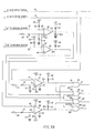
- Figs. 5A and 5B constitute a schematic circuit diagram of the direction sensitive collision avoidance circuit of the system of Fig. 2; and
- Fig. 6 is a graph showing the relationship between the velocity of the trailing arm and the distance between the arms.
- Fig. 1 shows two arms A and X of a two arm robot being driven in a common direction along a
common path 10. Arm A is being driven topoint 12, while arm X is being driven topoint 11. In this situation, a collision between arms A and X, or between probes or other equipment carried by the arms, is possible if the speed of arm X, the trailing arm, is greater than the speed of arm A, the leading arm. According to the invention, a collision is avoided by decreasing the speed of trailing arm X as the distance between the arms becomes equal to or smaller than a predetermined distance. - The collision avoidance system of the invention is shown in Fig. 2. A
conventional controller 14, such as an Ormec Model 901 controller, generates a drive signal for arm X onX-axis control line 15 and a drive signal for arm A onA-axis control line 16. These arms feed the drive signals as inputs to a direction sensitivecollision avoidance circuit 17 which will be described more fully below with reference to Figs. 5A and 5B. A- andX-axis position sensors 20 develop a pair of slowdown or "slow" signals onlines position sensors 20 when the distance between the arms falls to an even smaller separation, such as 1/inch. This "stop" signal is coupled online 23 to controller 14 to cause the controller to discontinue the drive signals onlines - As will be explained more fully below, direction sensitive
collision avoidance circuit 17 includes speed reducing means which, in response to "slow" signals onlines X-axis control line 24 toX-axis servo amplifier 26 and onA-axis control line 25 toA-axis servo amplifier 27. Drive current from X-axisservo amplifier 26 is fed toservo drive motor 28 which drives arm X, and drive current from A-axisservo amplifier 27 is fed to drivemotor 29 which drives arm A. - As is known in the art,
position detectors leads controller 14. The position detectors may, for example, be in the form of glass scales which cooperate with lamp-photoreceiver pairs. Alternatively, stepping motors could be used asmotors -
Position sensors 20 are embodied in the structure shown in Figs. 3 and 4. Amask member 35, which may, for example be mounted on arm X, extends toward arm A and is positioned substantially parallel topath 10.Mask member 35 includes two steps or cutouts creating three portions of different length.Portion 36, extending the full length ofmask member 35, establishes a first predetermined separation distance. A first step defines asecond portion 37 which establishes a second predetermined separation distance, and a second step forms athird portion 38 defining a third predetermined separation distance. A sensor mounting board orhousing 40 supports threephotosensors mask portions bracket 44 on which are mountedphotosensor housing 40 and, spaced fromhousing 40, a lamp mounting board orhousing 46, on which are mountedlamps photosensors bracket 50, which is mounted on arm X (see Fig. 3), supportsmask member 35 which moves in a plane extending betweenhousings mask portion 36 extends betweenlamp 47 andphotosensor 41 blocking the light fromlamp 47. As a result,photosensor 41 generates the first "slow" signal. Likewise, whenmask portion 37 is blocking the light betweenlamp 48 andphotosensor 42, the arms are separated by a distance equal to or less than the second predetermined distance; this results in the generation of the second "slow" signal byphotosensor 42. Finally, whenmask portion 38 blocks the light from lamp 49 from reachinglimit photosensor 43, the arms are separated by a distance equal to or less than the third predetermined distance.Photosensor 43 then generates the "stop" signal. Although the position sensors are shown as using lamps and photosensors on separate mounting boards or housings, it will be understood that the lamps and photosensors could be placed on a common mounting board or housing. In that case, the sensors would operate on a reflecting rather than a blocking principle. - Turning to Figs. 5A and 5B, it will be seen that direction sensitive
collision avoidance circuit 17 receives the X-axis and A-axis drive signals onlines lines line 21 is applied to acomparator 52 by connection to its -input terminal 53. The +input terminal 54 is connected through a 1,000ohm resistor 57 to a +12volt reference source 58 and through a 1,000ohm resistor 59 to ground. The -terminal 53 is also connected through a 12,000ohm resistor 55 to a +12volt source 56. The output line 52a fromcomparator 52 is connected through a 1,000ohm resistor 60 to a +5volt source 61. When the first "slow" signal is absent fromlead 21, the voltage atinput 53 will be greater than that of the reference voltage oninput 54; and the output on lead 52a will be low. When, on the other hand, the first "slow" signal is present onlead 21, the voltage oninput 53 will not be greater than the reference voltage oninput 54; and the output on lead 52a will be high. A 150microfarad capacitor 60a is connected between line 52a and ground This introduces a time delay to keep line 52a high for a short time when the "slow" signal is removed frominput 53, preventing oscillations. - The second "slow" signal on
lead 22 is applied to the -input 63 ofcomparator 62.Input 63 is also connected through a 12,000ohm resistor 65 to a +12volt source 66. The +input 64 ofcomparator 62 is connected to + input 54 ofcomparator 52 and, hence, to the +12volt reference 58 throughresistor 57 and to ground throughresistor 59. The output fromcomparator 62 appear onoutput line 62a which is connected through a 1,000ohm resistor 67 to a +5volt source 68. If the second "slow" signal is absent fromlead 22, the output onlead 62a will be low. If, on the other hand, the second "slow" signal is present onlead 22,output lead 62a will be high. - The A-axis drive signal on
lead 16 is applied to the -input 71 of acomparator 70, the +input 72 of which is connected through a 1,000ohm resistor 73 to a +12 voltreference voltage source 74 and throughdiode 75 to ground. A +12volt source 76 and a -12 volt source 77 are also provided directly to bias terminals ofcomparator 70, and another terminal 78 is grounded. The output line 70a fromcomparator 70 is connected through a 1,000ohm resistor 79 to a +5 colt source 80. When the A-axis drive signal onlead 15 is negative, the output fromcomparator 70 will be high. A positive A-axis drive signal will result in a low output on lead 70a. - The X-axis drive signal on
lead 15 is applied to + input 83 ofcomparator 82, the -input 84 of which is grounded throughdiode 87 and connected through a 1,000ohm resistor 85 to a -12 voltreference voltage source 86. Bias voltages of +12 volts and -12 volts are applied fromsources comparator 82 which is grounded throughterminal 90. The output lead 82a is connected through a 1,000ohm resistor 91 to a +5volt source 92. When the X-axis drive signal is positive, the output on lead 82a will be high. A negative X-axis drive signal will produce a low output on lead 82a. - A logic circuit including four AND
gates leads 52a, 62a, 70a and 82a. ANDgate 94 receives the output from lead 70a oninput 95 and the output from lead 52a onlead 96. The presence of high signals oninputs output lead 97; otherwise, the output will be low. ANDgate 98 receives the output from lead 70a oninput 99 and from lead 62a oninput 100. If high signals are present on both inputs, the output onlead 101 is high. if this is not the case, a low output is found onlead 101. ANDgate 102 has an input 103 connected to lead 52a and aninput 104 connected to lead 82a. When high signals are on both inputs, a high output appears onlead 105. For other signal combinations on theinputs 103 and 104, the output onlead 105 is low. ANDgate 106 has aninput 107 connected to lead 62a and aninput 108 connected to lead 82a. The presence of high signals onleads output 109. Any other signal combination oninputs output 109. - The system includes speed reducing means, two for arm A and two for arm X, comprising resistors inserted in series between the controller and the servo amplifiers. These resistors are normally shorted by switch means controlled by the logic circuit. Thus,
line 16 for the A-axis drive signal is in series with a 1,000ohm resistor 128, a 6,800ohm resistor 138 and A-axisdrive signal line 25.Shunt resistors resistors line 25.Lines speed reducing resistors resistors resistors line 24. -
Resistor 128 is normally shunted by switch means 117 which is a conventional CMOS switch comprising an N-channel FET 120 and a P-channel FET 124, both shunted acrossresistor 128.FETs control switch circuit 110 which is connected directly to thegate electrode 121 ofFET 120 and throughinverter 122 to thegate electrode 125 ofFET 124. When the input to controlswitch 110 is a logic low, the switch is closed applying a high input togate electrode 121 ofFET 120 and a low input, by virtue ofinverter 122, togate electrode 125 ofFET 124, causing the FETs to be conductive andshort circuiting resistor 128. When, on the other hand, the input to controlswitch 110 is a logic high, the switch is open applying a low input togate electrode 121 ofFET 120 and a high input, due toinverter 122, togate electrode 125 ofFET 124. The FETs will therefore become non-conductive, removing the short circuit fromresistor 128. This will insert the resistor in the series circuit between A-axisdrive signal lines channel FET 130 and P-channel FET 134, is actuated bycontrol switch circuit 112, whenline 101 is low, by virtue of the direct connection togate electrode 131 ofFET 130 and the connection throughinverter 132 togate electrode 135 ofFET 134, to maintain a short circuit acrossresistor 138. Whenline 101 from ANDgate 98 is high,control switch 112 will deactivate switch means 118.FETs resistor 138 in the series circuit. CMOS switch means 117a and 118a likewiseshort circuit resistors channel FET 140 and P-channel FET 144 connected acrossresistor 148 withswitch 114 directly connected togate electrode 141 ofFET 140 and throughinverter 142 togate electrode 145 ofFET 144, is triggered bycontrol switch circuit 114 whenline 105 from ANDgate 102 is low and deactivated whenline 105 is high. Switch means 117a thusshort circuits resistor 148 when 105 is low, but inserts the resistor in the series circuit when 105 is high. Switch means 118a operates in the same way with reference to whetherline 109 from ANDgate 106 is high or low and comprises N-channel FET 150 and P-channel FET 154 connected acrossresistor 158. The FETs are actuated bycontrol switch circuit 116, which is connected directly togate electrode 151 ofFET 150 and throughinverter 152 togate electrode 155 ofFET 154, toshort circuit resistor 158 when 109 is low and to insertresistor 158 in the series circuit when 109 is high. - The operation of the system will be understood with reference to Fig. 6 which contains a curve showing the relationship between the velocity of the trailing arm and the distance between the arms. If it is assumed that arm X is trailing arm A, as is shown in Fig. 1, and that the separation between the arms is greater than three inches, then the velocity of the trailing arm X will be at its maximum 160, which in the example shown in the curve of Fig. 6 is twenty inches per second. At that time, these will be no "slow" signals from the
position sensors 20 onleads outputs 52a and 62a will be low. The X-axis drive signal online 15 fromcontroller 14 is applied to + input 83 ofcomparator 82. Since arm X is being driven in the direction of arm A, the X-axis drive signal is positive. This is sensed bycomparator 82 which produces a high signal on output lines 82a. The A-axis drive signal online 16 is also positive, indicating that leading arm A is moving in the same direction as arm X. When, however, the positive A-axis drive signal is applied to -input 71 ofcomparator 70, the output 70a will remain low, thus inhibiting ANDgates inputs gates comparators outputs gates outputs gates speed reducing resistors - If we now assume that the trailing arm X is gaining on leading arm A and that the distance between the arms has become equal to or less than three inches,
mask portion 36 ofmask member 35 blocks light fromlamp 47 from reachingphotosensor 41. As a result,photosensor 41 generates a first "slow" signal onlead 21. When this "slow" signal is applied to input 103 of ANDgate 102, itsoutput 105 goes high. This causescontrol switch 114 to open and, in turn,FETs resistor 148. The system has now switched into a slowdown mode.Resistor 148 is now in series between X-axisdrive signal lines servo amplifier 26 and reducing the drive current fed to drivemotor 28. This causes the velocity of trailing arm X to drop to its first "slow"speed 162, which in the example shown is about one half the maximum speed. - If arm X continues to gain on arm A until the separation is reduced to one inch or less,
mask portion 37 will assume a position in which it blocks the light fromlamp 48 from being received byphotosensor 42. This causes the photosensor to generate the second "slow" signal onlead 22. The presence of the second "slow" signal is sensed bycomparator 62 andoutput 62a become high. When this high signal is applied to input 107 of ANDgate 106, theoutput 109 goes high andcontrol switch 116opens causing FETs speed reducing resistor 158.Resistors drive signal lines servo amplifier 26, and the magnitude of the drive current supplied by the servo amplifier to drivemotor 28. This causes the velocity of trailing arm X to be further reduced to avelocity 164 which, in the example, is about two inches per second. - It may sometime be the case that, notwithstanding two slowdowns, the arms come close to a collision. This may be due to some kind of malfunction which may, for example, cause the arms to be driven in opposite directions toward each other. If the separation between the arms is reduced to a small predetermined distance, such as the quarter inch separation shown in the example of Fig. 6,
mask portion 38 will block the light from lamp 49 from reachingphotosensor 43. This will causephotosensor 43 to generate a "stop" signal which is applied online 23 tocontroller 14. In response, the controller discontinues the X-axis and A-axis drive signals causingdrive motors - Although the operation of the system has been described with reference to the situation in which arm X trails arm A, it will be understood that the operation when arm A trails arm X will be generally similar. Since the arms will, in this case, be driven in the opposite direction, the polarity of the X-axis and A-axis drive signals will be negative. When the negative A-axis drive signal is applied to input 71 of
comparator 70, the output 70a will become high. This will enable ANDgates lead 21, comparator output 52a becomes high and, as a result, ANDgate 94output 97 goes high. This causesswitch 110 to open bringing its output low to deactivate switch means 117, placingspeed reducing resistor 128 in series with A-axisdrive signal lines line 22 results in a high output oncomparator output lead 62a; and ANDgate 98output 101 goes high, in response to whichswitch 112 opens. Switch means 118 therefore is deactivated to placespeed reducing resistor 138 in the series circuit between A-axisdrive signal lines motor 29 is thus slowed to speed 162 when one "slow" signal is present and to speed 164 when both "slow" signals are present. On the other hand, the negative X-axis drive signal online 15 applied to input 83 ofcomparator 82 results in a low output on output lead 82a, thus inhibiting ANDgates
Claims (10)
characterized in that there are provided:
sensing means (20) for sensing the distance between said first object (A) and said second object (X), said sensing means generating at least one "slow" signal when said distance between said first object and said second object is equal to or less than at least one predetermined distance; and
control means (17) responsive to said "slow" signal for reducing the speed of said second object to at least one first slow speed.
wherein the control means comprise logic circuit means (94-106) for generating a first control signal when said first object is being driven toward said second object and said "slow" signal is present and for generating a second control signal when said second object is being driven toward said first object and said "slow" signal is present;
wherein the second control signal enables said speed reducing means (148, 158) of said second drive means;
and wherein further speed reducing means (128, 138) are provided for said first drive means, the further speed reducing means being enabled by the first control signal.
Applications Claiming Priority (2)
| Application Number | Priority Date | Filing Date | Title |
|---|---|---|---|
| US788262 | 1985-10-17 | ||
| US06/788,262 US4644237A (en) | 1985-10-17 | 1985-10-17 | Collision avoidance system |
Publications (2)
| Publication Number | Publication Date |
|---|---|
| EP0222113A2 true EP0222113A2 (en) | 1987-05-20 |
| EP0222113A3 EP0222113A3 (en) | 1989-02-01 |
Family
ID=25143940
Family Applications (1)
| Application Number | Title | Priority Date | Filing Date |
|---|---|---|---|
| EP86112936A Ceased EP0222113A3 (en) | 1985-10-17 | 1986-09-19 | Collision avoidance system |
Country Status (3)
| Country | Link |
|---|---|
| US (1) | US4644237A (en) |
| EP (1) | EP0222113A3 (en) |
| JP (1) | JPS6294288A (en) |
Cited By (3)
| Publication number | Priority date | Publication date | Assignee | Title |
|---|---|---|---|---|
| DE102004026827A1 (en) * | 2004-05-28 | 2005-12-22 | Hiersemann Prozessautomation Gmbh | Operations sequence monitoring method, involves processing operations, in which robot and operator achieve tasks according to program and robot moves within common workspace |
| DE102005003827A1 (en) * | 2005-01-26 | 2006-07-27 | Fraunhofer-Gesellschaft zur Förderung der angewandten Forschung e.V. | Interactive device for cooperation between a person and a robot unit at a work station with a robot unit has sensor units to detect how close the person is |
| DE102005037650A1 (en) * | 2005-08-05 | 2007-02-08 | Reis Gmbh & Co. Kg Maschinenfabrik | Safety system designed to prevent collisions between individuals and static- or mobile robots, compares their relative positions, warns of impending hazard, and shuts down if appropriate |
Families Citing this family (76)
| Publication number | Priority date | Publication date | Assignee | Title |
|---|---|---|---|---|
| JPS6352991A (en) * | 1986-08-20 | 1988-03-07 | トキコ株式会社 | Industrial robot |
| JPS63273909A (en) * | 1987-05-01 | 1988-11-11 | Honda Motor Co Ltd | Teaching controller for industrial robot |
| US5067872A (en) * | 1987-06-18 | 1991-11-26 | Knorr Brake Holding Corporation | Method for semitrailer transfer |
| US4973206A (en) * | 1987-06-18 | 1990-11-27 | General Signal Corporation | Method and apparatus for loading and unloading semitrailers and off railroad flat cars |
| DE3730105A1 (en) * | 1987-09-08 | 1989-03-16 | Pietzsch Ibp Gmbh | METHOD AND DEVICE FOR SECURING A VEHICLE OR DEVICE MOVING IN SPACE |
| JPH01230107A (en) * | 1988-03-10 | 1989-09-13 | Fanuc Ltd | Method for detecting collision of body to be driven by servomotor |
| JPH02135193U (en) * | 1989-04-14 | 1990-11-09 | ||
| US5304906A (en) * | 1989-12-26 | 1994-04-19 | Fanuc Ltd. | Collision detecting method using an observer |
| US5247608A (en) * | 1991-04-01 | 1993-09-21 | At&T Bell Laboratories | Method and apparatus for achieving dynamic path control of multiple robots |
| US5230783A (en) * | 1991-05-15 | 1993-07-27 | The Dow Chemical Company | Electrolytic cell and process for the labeling of proteins and peptides |
| JPH0553634A (en) * | 1991-08-29 | 1993-03-05 | Matsushita Electric Ind Co Ltd | Multi-arm interference evading system |
| JP2785086B2 (en) * | 1992-06-17 | 1998-08-13 | ファナック株式会社 | Robot manual feed method |
| JPH06250717A (en) * | 1993-02-23 | 1994-09-09 | Fanuc Ltd | Acceleration and deceleration control system for numerical controller |
| US5481248A (en) * | 1993-03-11 | 1996-01-02 | Kruh; Brian A. | Overhead cranes having collision avoidance capabilities |
| DE4443669A1 (en) * | 1994-12-08 | 1996-06-13 | Index Werke Kg Hahn & Tessky | Method and device for monitoring the movement of a machine component |
| CN1046454C (en) * | 1995-06-13 | 1999-11-17 | 东洋钢钣株式会社 | Interference preventing method for industrial robots |
| US6004016A (en) * | 1996-08-06 | 1999-12-21 | Trw Inc. | Motion planning and control for systems with multiple mobile objects |
| US6057777A (en) * | 1997-07-31 | 2000-05-02 | Laser Technology | Industrial position sensor |
| US6173215B1 (en) * | 1997-12-19 | 2001-01-09 | Caterpillar Inc. | Method for determining a desired response to detection of an obstacle |
| US8944070B2 (en) * | 1999-04-07 | 2015-02-03 | Intuitive Surgical Operations, Inc. | Non-force reflecting method for providing tool force information to a user of a telesurgical system |
| NL1020506C2 (en) * | 2002-05-01 | 2003-11-21 | Altech Logistiek B V | Work trolley for greenhouses. |
| CN1304178C (en) * | 2004-05-24 | 2007-03-14 | 熊勇刚 | Method for testing collision between joint of robot with multiple mechanical arm |
| US7979157B2 (en) * | 2004-07-23 | 2011-07-12 | Mcmaster University | Multi-purpose robotic operating system and method |
| JP3907649B2 (en) * | 2004-09-02 | 2007-04-18 | ファナック株式会社 | Interference prevention control device between robots |
| US9789608B2 (en) | 2006-06-29 | 2017-10-17 | Intuitive Surgical Operations, Inc. | Synthetic representation of a surgical robot |
| JP4995458B2 (en) * | 2005-12-12 | 2012-08-08 | 本田技研工業株式会社 | Legged mobile robot |
| KR101477121B1 (en) | 2006-06-13 | 2014-12-29 | 인튜어티브 서지컬 인코포레이티드 | Minimally invasive surgical system |
| US9718190B2 (en) * | 2006-06-29 | 2017-08-01 | Intuitive Surgical Operations, Inc. | Tool position and identification indicator displayed in a boundary area of a computer display screen |
| US20090192523A1 (en) | 2006-06-29 | 2009-07-30 | Intuitive Surgical, Inc. | Synthetic representation of a surgical instrument |
| US10008017B2 (en) | 2006-06-29 | 2018-06-26 | Intuitive Surgical Operations, Inc. | Rendering tool information as graphic overlays on displayed images of tools |
| US10258425B2 (en) | 2008-06-27 | 2019-04-16 | Intuitive Surgical Operations, Inc. | Medical robotic system providing an auxiliary view of articulatable instruments extending out of a distal end of an entry guide |
| US9207673B2 (en) * | 2008-12-04 | 2015-12-08 | Crown Equipment Corporation | Finger-mounted apparatus for remotely controlling a materials handling vehicle |
| US9122276B2 (en) | 2006-09-14 | 2015-09-01 | Crown Equipment Corporation | Wearable wireless remote control device for use with a materials handling vehicle |
| US8970363B2 (en) | 2006-09-14 | 2015-03-03 | Crown Equipment Corporation | Wrist/arm/hand mounted device for remotely controlling a materials handling vehicle |
| US9645968B2 (en) * | 2006-09-14 | 2017-05-09 | Crown Equipment Corporation | Multiple zone sensing for materials handling vehicles |
| US9089256B2 (en) | 2008-06-27 | 2015-07-28 | Intuitive Surgical Operations, Inc. | Medical robotic system providing an auxiliary view including range of motion limitations for articulatable instruments extending out of a distal end of an entry guide |
| US8903546B2 (en) | 2009-08-15 | 2014-12-02 | Intuitive Surgical Operations, Inc. | Smooth control of an articulated instrument across areas with different work space conditions |
| US8620473B2 (en) | 2007-06-13 | 2013-12-31 | Intuitive Surgical Operations, Inc. | Medical robotic system with coupled control modes |
| US9138129B2 (en) | 2007-06-13 | 2015-09-22 | Intuitive Surgical Operations, Inc. | Method and system for moving a plurality of articulated instruments in tandem back towards an entry guide |
| US9469034B2 (en) | 2007-06-13 | 2016-10-18 | Intuitive Surgical Operations, Inc. | Method and system for switching modes of a robotic system |
| US9084623B2 (en) | 2009-08-15 | 2015-07-21 | Intuitive Surgical Operations, Inc. | Controller assisted reconfiguration of an articulated instrument during movement into and out of an entry guide |
| US8864652B2 (en) * | 2008-06-27 | 2014-10-21 | Intuitive Surgical Operations, Inc. | Medical robotic system providing computer generated auxiliary views of a camera instrument for controlling the positioning and orienting of its tip |
| US9522817B2 (en) | 2008-12-04 | 2016-12-20 | Crown Equipment Corporation | Sensor configuration for a materials handling vehicle |
| US8918211B2 (en) | 2010-02-12 | 2014-12-23 | Intuitive Surgical Operations, Inc. | Medical robotic system providing sensory feedback indicating a difference between a commanded state and a preferred pose of an articulated instrument |
| US9492927B2 (en) | 2009-08-15 | 2016-11-15 | Intuitive Surgical Operations, Inc. | Application of force feedback on an input device to urge its operator to command an articulated instrument to a preferred pose |
| US8386080B2 (en) * | 2009-09-15 | 2013-02-26 | Harris Corporation | Robotic apparatus implementing collision avoidance scheme and associated methods |
| EP2493664B1 (en) | 2009-10-27 | 2019-02-20 | Battelle Memorial Institute | Semi-autonomous multi-use robot system and method of operation |
| US20130303944A1 (en) | 2012-05-14 | 2013-11-14 | Intuitive Surgical Operations, Inc. | Off-axis electromagnetic sensor |
| US9452276B2 (en) | 2011-10-14 | 2016-09-27 | Intuitive Surgical Operations, Inc. | Catheter with removable vision probe |
| DE112012005650B4 (en) * | 2012-01-13 | 2018-01-25 | Mitsubishi Electric Corporation | Risk measurement system |
| US20140148673A1 (en) | 2012-11-28 | 2014-05-29 | Hansen Medical, Inc. | Method of anchoring pullwire directly articulatable region in catheter |
| CN110279427B (en) | 2012-12-10 | 2024-01-16 | 直观外科手术操作公司 | Collision avoidance during controlled movement of movable arm of image acquisition device and steerable device |
| US10507066B2 (en) | 2013-02-15 | 2019-12-17 | Intuitive Surgical Operations, Inc. | Providing information of tools by filtering image areas adjacent to or on displayed images of the tools |
| EP2923669B1 (en) | 2014-03-24 | 2017-06-28 | Hansen Medical, Inc. | Systems and devices for catheter driving instinctiveness |
| EP3200718A4 (en) | 2014-09-30 | 2018-04-25 | Auris Surgical Robotics, Inc | Configurable robotic surgical system with virtual rail and flexible endoscope |
| US10314463B2 (en) | 2014-10-24 | 2019-06-11 | Auris Health, Inc. | Automated endoscope calibration |
| DE102014222857A1 (en) * | 2014-11-10 | 2016-05-12 | Kuka Roboter Gmbh | Flexible time-optimized sharing of a working space for robots |
| US10143526B2 (en) | 2015-11-30 | 2018-12-04 | Auris Health, Inc. | Robot-assisted driving systems and methods |
| US9931025B1 (en) | 2016-09-30 | 2018-04-03 | Auris Surgical Robotics, Inc. | Automated calibration of endoscopes with pull wires |
| US10244926B2 (en) | 2016-12-28 | 2019-04-02 | Auris Health, Inc. | Detecting endolumenal buckling of flexible instruments |
| US10766140B2 (en) | 2017-04-13 | 2020-09-08 | Battelle Memorial Institute | Teach mode collision avoidance system and method for industrial robotic manipulators |
| CN110831498B (en) | 2017-05-12 | 2022-08-12 | 奥瑞斯健康公司 | Biopsy device and system |
| WO2019005872A1 (en) | 2017-06-28 | 2019-01-03 | Auris Health, Inc. | Instrument insertion compensation |
| US10426559B2 (en) | 2017-06-30 | 2019-10-01 | Auris Health, Inc. | Systems and methods for medical instrument compression compensation |
| US10145747B1 (en) | 2017-10-10 | 2018-12-04 | Auris Health, Inc. | Detection of undesirable forces on a surgical robotic arm |
| JP7362610B2 (en) | 2017-12-06 | 2023-10-17 | オーリス ヘルス インコーポレイテッド | System and method for correcting uncommanded instrument rotation |
| AU2018384820A1 (en) | 2017-12-14 | 2020-05-21 | Auris Health, Inc. | System and method for estimating instrument location |
| EP3752085A4 (en) | 2018-02-13 | 2021-11-24 | Auris Health, Inc. | System and method for driving medical instrument |
| EP3856064A4 (en) | 2018-09-28 | 2022-06-29 | Auris Health, Inc. | Systems and methods for docking medical instruments |
| US11641121B2 (en) | 2019-02-01 | 2023-05-02 | Crown Equipment Corporation | On-board charging station for a remote control device |
| WO2020159636A1 (en) | 2019-02-01 | 2020-08-06 | Crown Equipment Corporation | Pairing a remote control device to a vehicle |
| KR20220123076A (en) | 2019-12-31 | 2022-09-05 | 아우리스 헬스, 인코포레이티드 | Alignment Techniques for Transdermal Access |
| EP4084721A4 (en) | 2019-12-31 | 2024-01-03 | Auris Health Inc | Anatomical feature identification and targeting |
| KR20220123087A (en) | 2019-12-31 | 2022-09-05 | 아우리스 헬스, 인코포레이티드 | Alignment interface for transdermal access |
| AU2021325685B2 (en) | 2020-08-11 | 2024-04-04 | Crown Equipment Corporation | Remote control device |
| GB2622565A (en) * | 2022-07-15 | 2024-03-27 | Taylor Hobson Ltd | A collision protection apparatus |
Citations (7)
| Publication number | Priority date | Publication date | Assignee | Title |
|---|---|---|---|---|
| US1976611A (en) * | 1932-10-04 | 1934-10-09 | Westinghouse Electric & Mfg Co | Regulating system |
| DE1171581B (en) * | 1960-01-14 | 1964-06-04 | Huetten Und Bergwerke Rheinhau | Device to avoid crane collisions |
| DE1246858B (en) * | 1965-08-06 | 1967-08-10 | Siemens Ag | Temperature controller with pointer mechanism |
| DE1538533A1 (en) * | 1965-11-29 | 1970-04-09 | Gen Electric | Control device with multi-point behavior |
| DE2114621B2 (en) * | 1971-03-26 | 1974-06-06 | Messerschmitt-Boelkow-Blohm Gmbh, 8000 Muenchen | Method and arrangement for automatic, distance-secured braking and travel control of objects located on the same path or lane |
| US4238716A (en) * | 1978-09-27 | 1980-12-09 | The United States Of America As Represented By The Secretary Of The Air Force | Miniature vehicle dispenser spin-up speed control system |
| EP0052263A1 (en) * | 1980-11-14 | 1982-05-26 | Inventio Ag | Device to keep track-bound vehicles at a distance from one another |
Family Cites Families (5)
| Publication number | Priority date | Publication date | Assignee | Title |
|---|---|---|---|---|
| US3442347A (en) * | 1965-03-31 | 1969-05-06 | Robert W Hodgson | Safe trailing distance maintenance system for a trailing carrier vehicle |
| DE2156001B2 (en) * | 1971-11-11 | 1975-10-16 | Daimler-Benz Ag, 7000 Stuttgart | Distance warning device for vehicles |
| US4026654A (en) * | 1972-10-09 | 1977-05-31 | Engins Matra | System for detecting the presence of a possibly moving object |
| WO1982003283A1 (en) * | 1981-03-16 | 1982-09-30 | Fujiwara Kunio | Movement controller for moving body |
| JPS5810483A (en) * | 1981-07-08 | 1983-01-21 | 日産自動車株式会社 | Method and device for preventing collision at high speed of both arm in two-arm robot |
-
1985
- 1985-10-17 US US06/788,262 patent/US4644237A/en not_active Expired - Fee Related
-
1986
- 1986-09-08 JP JP61209800A patent/JPS6294288A/en active Granted
- 1986-09-19 EP EP86112936A patent/EP0222113A3/en not_active Ceased
Patent Citations (7)
| Publication number | Priority date | Publication date | Assignee | Title |
|---|---|---|---|---|
| US1976611A (en) * | 1932-10-04 | 1934-10-09 | Westinghouse Electric & Mfg Co | Regulating system |
| DE1171581B (en) * | 1960-01-14 | 1964-06-04 | Huetten Und Bergwerke Rheinhau | Device to avoid crane collisions |
| DE1246858B (en) * | 1965-08-06 | 1967-08-10 | Siemens Ag | Temperature controller with pointer mechanism |
| DE1538533A1 (en) * | 1965-11-29 | 1970-04-09 | Gen Electric | Control device with multi-point behavior |
| DE2114621B2 (en) * | 1971-03-26 | 1974-06-06 | Messerschmitt-Boelkow-Blohm Gmbh, 8000 Muenchen | Method and arrangement for automatic, distance-secured braking and travel control of objects located on the same path or lane |
| US4238716A (en) * | 1978-09-27 | 1980-12-09 | The United States Of America As Represented By The Secretary Of The Air Force | Miniature vehicle dispenser spin-up speed control system |
| EP0052263A1 (en) * | 1980-11-14 | 1982-05-26 | Inventio Ag | Device to keep track-bound vehicles at a distance from one another |
Non-Patent Citations (1)
| Title |
|---|
| RADIO FERNSEHEN-ELEKTRONIK * |
Cited By (6)
| Publication number | Priority date | Publication date | Assignee | Title |
|---|---|---|---|---|
| DE102004026827A1 (en) * | 2004-05-28 | 2005-12-22 | Hiersemann Prozessautomation Gmbh | Operations sequence monitoring method, involves processing operations, in which robot and operator achieve tasks according to program and robot moves within common workspace |
| DE102004026827B4 (en) * | 2004-05-28 | 2006-03-02 | Hiersemann Prozessautomation Gmbh | Operations sequence monitoring method, involves processing operations, in which robot and operator achieve tasks according to program and robot moves within common workspace |
| DE102005003827A1 (en) * | 2005-01-26 | 2006-07-27 | Fraunhofer-Gesellschaft zur Förderung der angewandten Forschung e.V. | Interactive device for cooperation between a person and a robot unit at a work station with a robot unit has sensor units to detect how close the person is |
| DE102005003827B4 (en) * | 2005-01-26 | 2007-01-04 | Fraunhofer-Gesellschaft zur Förderung der angewandten Forschung e.V. | Apparatus and method for interaction between a human and a robot unit at a robot workstation |
| DE102005037650A1 (en) * | 2005-08-05 | 2007-02-08 | Reis Gmbh & Co. Kg Maschinenfabrik | Safety system designed to prevent collisions between individuals and static- or mobile robots, compares their relative positions, warns of impending hazard, and shuts down if appropriate |
| EP1752702A1 (en) | 2005-08-05 | 2007-02-14 | Reis GmbH & Co. KG Maschinenfabrik | Method and system for monitoring collisions between robots and persons |
Also Published As
| Publication number | Publication date |
|---|---|
| EP0222113A3 (en) | 1989-02-01 |
| US4644237A (en) | 1987-02-17 |
| JPS6294288A (en) | 1987-04-30 |
| JPH0443745B2 (en) | 1992-07-17 |
Similar Documents
| Publication | Publication Date | Title |
|---|---|---|
| US4644237A (en) | Collision avoidance system | |
| EP2952928A1 (en) | Laser sensor and automatic guided device | |
| US5075632A (en) | Automatic control using proximity sensors | |
| WO1993003399A1 (en) | Obstacle detecting assembly | |
| US5481248A (en) | Overhead cranes having collision avoidance capabilities | |
| AU566331B2 (en) | Detecting proximity to electrical power lines | |
| US3483455A (en) | Malfunction detection circuit | |
| JPH07111703A (en) | Safety device for vehicle | |
| KR900002886A (en) | Wire electrode supply device of wire discharge processing equipment | |
| KR840008438A (en) | Constant current and potentiostatic automatic control system for air-carbon arc metal removal | |
| KR100462612B1 (en) | Method and apparatus for controlling DC-motor | |
| US5986423A (en) | Industrial robot | |
| JP2831166B2 (en) | Driver controller for vertical linear motor | |
| JPH03151679A (en) | Protective circuit of laser diode | |
| JP3144120B2 (en) | Bumper collision detection device | |
| JPS598496B2 (en) | Electric discharge machining equipment | |
| JPH0611531A (en) | Controller of electromagnetic equipment | |
| KR920019493A (en) | Position control device of robot system and its control method | |
| JPH0258591B2 (en) | ||
| JPS58215983A (en) | Speed control circuit with protector | |
| JPS6066680A (en) | Abnormality detecting circuit of motor drive controller | |
| JP3055714B2 (en) | Photoelectric switch | |
| JP2976147B2 (en) | Probe drive for scanning tunneling microscope | |
| KR0112797Y1 (en) | Control circuit for shock detector in headphone stereo | |
| KR0155722B1 (en) | Robot system of electric cut-off control |
Legal Events
| Date | Code | Title | Description |
|---|---|---|---|
| PUAI | Public reference made under article 153(3) epc to a published international application that has entered the european phase |
Free format text: ORIGINAL CODE: 0009012 |
|
| AK | Designated contracting states |
Kind code of ref document: A2 Designated state(s): DE FR GB IT |
|
| 17P | Request for examination filed |
Effective date: 19870821 |
|
| PUAL | Search report despatched |
Free format text: ORIGINAL CODE: 0009013 |
|
| AK | Designated contracting states |
Kind code of ref document: A3 Designated state(s): DE FR GB IT |
|
| RHK1 | Main classification (correction) |
Ipc: G05D 1/02 |
|
| 17Q | First examination report despatched |
Effective date: 19890607 |
|
| STAA | Information on the status of an ep patent application or granted ep patent |
Free format text: STATUS: THE APPLICATION HAS BEEN REFUSED |
|
| 18R | Application refused |
Effective date: 19910826 |
|
| RIN1 | Information on inventor provided before grant (corrected) |
Inventor name: FRUSHOUR, JAMES EDWARD Inventor name: MAJKA, CHRISTOPHER JOHN Inventor name: SWENSON, JOHN EDWARD Inventor name: MAHAR, MICHAEL LAWRENCE |