EP0221513B1 - Endschalter - Google Patents
Endschalter Download PDFInfo
- Publication number
- EP0221513B1 EP0221513B1 EP86115085A EP86115085A EP0221513B1 EP 0221513 B1 EP0221513 B1 EP 0221513B1 EP 86115085 A EP86115085 A EP 86115085A EP 86115085 A EP86115085 A EP 86115085A EP 0221513 B1 EP0221513 B1 EP 0221513B1
- Authority
- EP
- European Patent Office
- Prior art keywords
- cover
- limit switch
- casing
- spatter
- lever
- Prior art date
- Legal status (The legal status is an assumption and is not a legal conclusion. Google has not performed a legal analysis and makes no representation as to the accuracy of the status listed.)
- Expired
Links
- 238000003466 welding Methods 0.000 claims abstract description 10
- 239000011347 resin Substances 0.000 claims description 21
- 229920005989 resin Polymers 0.000 claims description 21
- 229920001971 elastomer Polymers 0.000 claims description 6
- 239000005060 rubber Substances 0.000 claims description 6
- 229920001296 polysiloxane Polymers 0.000 claims description 5
- -1 polytetrafluoroethylene Polymers 0.000 claims description 5
- PXHVJJICTQNCMI-UHFFFAOYSA-N Nickel Chemical compound [Ni] PXHVJJICTQNCMI-UHFFFAOYSA-N 0.000 claims description 4
- 229920001343 polytetrafluoroethylene Polymers 0.000 claims description 4
- 239000004810 polytetrafluoroethylene Substances 0.000 claims description 4
- 239000000919 ceramic Substances 0.000 claims description 3
- 229920003217 poly(methylsilsesquioxane) Polymers 0.000 claims description 3
- VYZAMTAEIAYCRO-UHFFFAOYSA-N Chromium Chemical compound [Cr] VYZAMTAEIAYCRO-UHFFFAOYSA-N 0.000 claims description 2
- KRHYYFGTRYWZRS-UHFFFAOYSA-M Fluoride anion Chemical compound [F-] KRHYYFGTRYWZRS-UHFFFAOYSA-M 0.000 claims description 2
- 229910052804 chromium Inorganic materials 0.000 claims description 2
- 239000011651 chromium Substances 0.000 claims description 2
- 229910052759 nickel Inorganic materials 0.000 claims description 2
- 239000000203 mixture Substances 0.000 claims 2
- 239000000463 material Substances 0.000 description 14
- 229910052754 neon Inorganic materials 0.000 description 9
- GKAOGPIIYCISHV-UHFFFAOYSA-N neon atom Chemical compound [Ne] GKAOGPIIYCISHV-UHFFFAOYSA-N 0.000 description 9
- 230000007935 neutral effect Effects 0.000 description 5
- 230000006835 compression Effects 0.000 description 4
- 238000007906 compression Methods 0.000 description 4
- 229910052782 aluminium Inorganic materials 0.000 description 3
- XAGFODPZIPBFFR-UHFFFAOYSA-N aluminium Chemical compound [Al] XAGFODPZIPBFFR-UHFFFAOYSA-N 0.000 description 3
- 239000011248 coating agent Substances 0.000 description 3
- 238000000576 coating method Methods 0.000 description 3
- 229910000838 Al alloy Inorganic materials 0.000 description 2
- 238000010276 construction Methods 0.000 description 2
- 230000000694 effects Effects 0.000 description 2
- 239000007769 metal material Substances 0.000 description 2
- 239000002923 metal particle Substances 0.000 description 2
- 238000000465 moulding Methods 0.000 description 2
- 230000002265 prevention Effects 0.000 description 2
- 238000007789 sealing Methods 0.000 description 2
- 239000010935 stainless steel Substances 0.000 description 2
- 229910001220 stainless steel Inorganic materials 0.000 description 2
- 229920000877 Melamine resin Polymers 0.000 description 1
- 238000005266 casting Methods 0.000 description 1
- 238000004512 die casting Methods 0.000 description 1
- 238000006073 displacement reaction Methods 0.000 description 1
- 239000004744 fabric Substances 0.000 description 1
- JDSHMPZPIAZGSV-UHFFFAOYSA-N melamine Chemical compound NC1=NC(N)=NC(N)=N1 JDSHMPZPIAZGSV-UHFFFAOYSA-N 0.000 description 1
- 229910052751 metal Inorganic materials 0.000 description 1
- 239000002184 metal Substances 0.000 description 1
- 238000000034 method Methods 0.000 description 1
- 238000012986 modification Methods 0.000 description 1
- 230000004048 modification Effects 0.000 description 1
- 229920001707 polybutylene terephthalate Polymers 0.000 description 1
- 230000001681 protective effect Effects 0.000 description 1
- 230000000717 retained effect Effects 0.000 description 1
- ABTOQLMXBSRXSM-UHFFFAOYSA-N silicon tetrafluoride Chemical compound F[Si](F)(F)F ABTOQLMXBSRXSM-UHFFFAOYSA-N 0.000 description 1
- 229920002379 silicone rubber Polymers 0.000 description 1
- 239000004945 silicone rubber Substances 0.000 description 1
- 230000000007 visual effect Effects 0.000 description 1
Images


Classifications
-
- H—ELECTRICITY
- H01—ELECTRIC ELEMENTS
- H01H—ELECTRIC SWITCHES; RELAYS; SELECTORS; EMERGENCY PROTECTIVE DEVICES
- H01H21/00—Switches operated by an operating part in the form of a pivotable member acted upon directly by a solid body, e.g. by a hand
- H01H21/02—Details
- H01H21/18—Movable parts; Contacts mounted thereon
- H01H21/22—Operating parts, e.g. handle
- H01H21/24—Operating parts, e.g. handle biased to return to normal position upon removal of operating force
- H01H21/28—Operating parts, e.g. handle biased to return to normal position upon removal of operating force adapted for actuation at a limit or other predetermined position in the path of a body, the relative movement of switch and body being primarily for a purpose other than the actuation of the switch, e.g. door switch, limit switch, floor-levelling switch of a lift
- H01H21/285—Operating parts, e.g. handle biased to return to normal position upon removal of operating force adapted for actuation at a limit or other predetermined position in the path of a body, the relative movement of switch and body being primarily for a purpose other than the actuation of the switch, e.g. door switch, limit switch, floor-levelling switch of a lift having an operating arm actuated by the movement of the body and mounted on an axis converting its rotating movement into a rectilinear switch activating movement
-
- H—ELECTRICITY
- H01—ELECTRIC ELEMENTS
- H01H—ELECTRIC SWITCHES; RELAYS; SELECTORS; EMERGENCY PROTECTIVE DEVICES
- H01H9/00—Details of switching devices, not covered by groups H01H1/00 - H01H7/00
- H01H9/18—Distinguishing marks on switches, e.g. for indicating switch location in the dark; Adaptation of switches to receive distinguishing marks
- H01H2009/188—Distinguishing marks on switches, e.g. for indicating switch location in the dark; Adaptation of switches to receive distinguishing marks with indication of rating
-
- H—ELECTRICITY
- H01—ELECTRIC ELEMENTS
- H01H—ELECTRIC SWITCHES; RELAYS; SELECTORS; EMERGENCY PROTECTIVE DEVICES
- H01H9/00—Details of switching devices, not covered by groups H01H1/00 - H01H7/00
- H01H9/16—Indicators for switching condition, e.g. "on" or "off"
- H01H9/161—Indicators for switching condition, e.g. "on" or "off" comprising light emitting elements
Definitions
- the present invention relates to a limit switch for use as a switch for detecting an object on a conveyor line or the like.
- a limit switch according to the preamble of claim 1 is known from DE-A-2 254 765.
- the cover of this known limit switch has a flat surface.
- GB-A-281 439 discloses a manually operated quick break electric switch having a space-consuming cover of a part-cylindrical shape.
- the invention is as claimed in claim 1.
- the curved or partly spherical convex surface of the cover prevents spatter expelled from a welding machine from being deposited thereon. Therefore, failure of the limit switch to operate is prevented and indications on the cover remain visible.
- FIG. 10 shows a conventional limit switch by way of example.
- the limit switch includes a casing 1 housing a switch mechanism 2 with its upper portion covered by a cover 3.
- the switch mechanism 2 includes an actuating member 2a which is operated upon by a plunger 4 movable by a rotatable shaft 6 disposed in a head 5 mounted on the casing 1.
- the rotatable shaft 6 has a flat portion 6a on its end disposed in the head 5.
- the rotatable shaft 6 is normally held in a neutral position by a plunger 8 pressed against the flat portion 6a of the shaft 6 under the resiliency of a compression coil spring 7 placed in the head 5.
- An actuating lever 6 has one end fixed to the opposite end of the rotatable shaft 6 by a hexagon socket head bolt 10.
- a roller 12 is rotatably mounted by a roller shaft 11 on the other end of the actuating lever 6.
- a rating plate 13 is attached to the cover 3.
- the limit switch 1 of this construction may be used on a conveyor line.
- a dog on the conveyor is moved into engagement with the roller 12 to turn the lever 9, the flat portion 6a of the rotatable shaft 6 is angularly moved to push the plunger 4.
- the actuating member 2a is pushed by the plunger 4 to operate the switch mechanism 2.
- Such an operation of the switch mechanism 2 can be detected through terminal screws 2b and 2c.
- the lever 9 returns to its neutral position since the rotatable shaft 6 returns to the neutral position under the resiliency of the compression coil spring 7 in the head 5.
- the plunger 4 now releases the actuating member 2a.
- the conventional limit switch is rugged in construction and reliable in operation when used in normal environments. However, when it is used in the vicinity of an arc welding machine or a spot welding machine, melted metal particles or spattered expelled from the welding machine can be deposited on the casing. The spatter deposit grows until it causes an operation failure of the limit switch. When the spatter is deposited on the actuating lever, the limit switch is apt to fail quickly. When the spatter is deposited on the rating plate, the indications on the rating plate cannot be confirmed. If the rating plate has a window for visually checking the energization of an operation indicating lamp within the cover, the spatter layer on the window prevents such visual checking of the lamp.
- FIGS. 1 and 2 show a limit switch according to an embodiment of the present invention.
- the limit switch includes a casing 1 in the form of a rectangular box in which a dual-circuit double-break switch mechanism 2 is fixedly disposed by screws through an insulating piece of cloth.
- the casing 1 has an opening closed by a cover 3 through a gasket 14, the cover 3 being secured to the casing by screws 15.
- the cover 3 comprises a transparent or semitransparent resin member 16 and an aluminum die-cast member 17 which are assembled together by outsert molding.
- the resin member 16 has a recess defined in the back thereof.
- a rating plate 13 is inserted in the recess of the resin member 16, and a lamp holder cover 22 of rubber with a neon lamp 19, a resistor 20, and a contact spring 21 mounted therein is placed in the recess over the rating plate 13.
- a transparent or semitransparent lamp indicator plate 23 is placed over the neon lamp 19.
- the contact spring 21 contacts a normally open terminal 2b when the cover 3 is mounted on the casing 1.
- the switch mechanism 2 has two normally open terminals 2b and two normally closed terminals 2c to which there are connected terminals of lead wires introduced through a connector into a conduit hole 24 defined in the casing 1.
- the switch mechanism 2 has an actuating member 2a contacted by a tip end 25a of an auxiliary plunger 25, which is slidably inserted into an actuating plunger 4 slidably mounted in the casing 1 by a bearing 26, with a protective compression spring 27 interposed between the auxiliary plunger 25 and the actuating plunger 4.
- the auxiliary plunger 25 is retained in place by a stopper ring 28 fitted in the open end of the actuating plunger 4.
- a sealing cap 29 of rubber and a contact member 30 are force-fitted over the distal end of the actuating plunger 4.
- a head 5 is secured to the casing 1 by four screws 31 so that head 5 covers the tip end of the actuating plunger 4.
- a return plunger 8 is slidably inserted in the head 5 in coaxial relation to the actuating plunger 4, the return plunger 8 being normally urged by a compression coil spring 7 toward the actuating plunger 4.
- the head 5 also houses therein a rotatable shaft 6 extending in a direction normal to the axis of the return plunger 8 and rotatably supported by a bearing 32.
- the rotatable shaft 6 is recessed at opposite surfaces facing the return plunger 8 and the actuating plunger 4 and defining a flat cam 6a.
- the return plunger 8 and the contact member 30 on the tip end of the actuating plunger 4 are pressed respectively against the opposite surfaces of the cam 6a under the resilient forces of the springs 7 and 27 to keep the rotatable shaft 6 in a neutral position.
- the rotatable shaft 6 has one end projecting from a boss 5a of the head 5, with an O-ring 33 interposed between the bearing 32 and the shaft 6.
- a cylindrical cap 34 of resin is fitted over the distal end of the boss 5a and has a hole through which the end of the rotatable shaft 6 extends.
- the projecting end of the rotatable shaft 6 is fitted in an attachment hole 9a defined in one end of an actuating lever 9.
- the actuating lever 9 has a slot 9b defined longitudinally across the attachment hole 9a.
- the actuating lever 9 is fastened to the rotatable shaft 6 by tightening a hexagon socket head bolt 10 which is threaded through the lever 9 across the slot 9b.
- a roller 12 is rotatably mounted on the distal end of the actuating lever 9 by a roller shaft 11 that is fixed to the lever 9 by staking its end 11a.
- the components ranging from the head 5 to the roller 12 jointly constitute the actuator of the limit switch.
- the four screws 31 by which the head 5 is attached to the casing 1 are positioned equidistantly around the axis of the actuating plunger 4 and extend in the same direction, so that the head 5 can be oriented with respect to the casing 1 in any of four 90-degree-spaced directions.
- the rating plate 13 has two spaced windows 13a and 13b of identical shape, as shown in FIG. 2.
- the energization of the neon lamp 19 can be confirmed through one of these windows.
- the neon lamp 19 is mounted in the lamp holder cover 22 disposed behind the cover 3. If the lamp holder cover 22 is fitted behind the cover 3 so as to allow the neon lamp 19 to be viewed through the window 13b, as shown, the contact spring 21 contacts the normally open terminal 2b of the switch mechanism 2, so that the neon lamp 19 is energized only when the switch mechanism 2 is turned off, indicating that the switch is not in operation. Conversely, if the lamp holder cover 19 is attached so that the neon lamp 19 can be viewed through the window 13a, the contact spring 21 contacts the normally closed terminal 2c of the switch mechanism 2. Therefore, the neon lamp 19 is energized only when the switch mechanism 2 is turned on to indicate that the switch is in operation. Such operative or inoperative condition of the switch is indicated by the lamp indicator plate 23 placed in front of the neon lamp 19 and bearing an indication mark.
- the casing 1 and the head 5 comprise die castings of an aluminum alloy
- the lever 9 comprises a casting of an aluminum alloy.
- the casing 1, the head 5, and the lever 9 are coated with a melamine layer for preventing spatter from being deposited thereon.
- These components can be coated with any of various materials which are highly resistant to heat and allow spatter deposits to be separated easily.
- these components may be coated with a resin such as polytetrafluoroethylene, silicone, silicon fluoride, glass resin, or a rubber or ceramics material, or may be plated with a metal such as nickel, chromium, or the like.
- the surfaces of the casing 1, the head 5, and the lever 9 are required to have smooth surfaces in order to allow spatter deposits to be separated easily.
- the casing 1, the head 5, and the lever 9 themselves may be made of these materials.
- the desired materials also include stainless steel, and the roller shaft 11, the roller 12, the hexagon socket head bolt 10, and the screws 31 are made of stainless steel.
- the entire limit switch including the casing 1 and the cover 3, may be coated with or made of any of the above desired materials.
- the resin cap 34 is disposed between the lever 9 and the head 5 for its heat resistance and ability to allow spatter deposits to be separated.
- the resin cap 34 is made of polytetrafluoroethylene in the illustrated embodiment, it may be formed of any other resin material which is heat-resistant and from which spatter deposits can easily be separated.
- the boss 5a, together with the rotatable shaft 6, may be entirely covered by the resin cap 34. Since the resin cap is flexible, it can be attached more easily and has a better sealing capability than it would if it were formed of other materials.
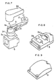
- the head of the hexagon socket head bolt 10 by which the lever 9 is fixed to the rotatable shaft 6 may be covered with a cap 35 made of a similar resin or rubber material.
- the cap 35 may be separated from a series of caps which are made of silicone rubber as shown in FIG. 5.
- the cap 35 may be shaped to cover the entire head of the hexagon socket head bolt 10 as shown in FIG. 6, or may be arranged to cover the head of another screw or close an attachment hole after the screw has been attached.
- the lever 9 and the boss 5a of the head 5 on which the lever 9 is supported may be covered with a cover 36 made of a similar resin, rubber, or metal material.
- the cover 36 may cover the whole assembly of the lever 9, the head 5, and the casing 1. In such a case, the cover should be large enough to allow the lever 9 to be moved with respect to the casing 1, or should have a flexible portion between the lever 9 and the casing 1.
- the cover 3 on the casing 1 has a curved convex surface as shown in FIG. 1.
- the curved convex surface may be a cylindrical surface having a vertical curvature, a cylindrical surface having a horizontal curvature, another curved convex surface, a partly spherical convex surface such for example as an elliptically or circularly spherical surface, or a combination of some of these convex surfaces.
- the curved convex surface or partly spherical surface of the cover 3 serves to scatter spatter from a welding machine into various directions when the spatter hits the cover 3. Therefore, spatter deposits are not easily formed on the cover 3.
- the cover 3 is made of a transparent resin
- the cover 3 has a lens effect to allow the indications on the rating plate 13 behind the transparent resin member 16 to be clearly visible.
- curved convex surfaces or partly spherical convex surfaces may be formed only over the windows 13a and 13b of the rating plate 13.
- the limit switch has an operation indicator lamp as shown, it is important to confirm the switch operation by visually checking the energization of the lamp.
- the curved convex surfaces or partly spherical convex surfaces over the windows 13a and 13b prevent spatter from being deposited over the windows 13a and 13b through which the lamp energization is to be confirmed, and also allows light from the lamp to be scattered by the lens effect.
- the cover 3 is formed by assembling the transparent resin member 16 of polybutylene terephthalate and the aluminum die-cast member 17 through the outsert molding process.
- the cover 3 may bodily be molded of transparent resin.
- the entire cover 3 may be formed of opaque resin or a metallic material such as die-cast aluminum. It is preferable for higher heat resistance to coat the curved convex surface or partly spherical convex surface or the resin surface with a highly-resistant material such as glass resin, ceramics, polytetrafluoroethylene, silicone, silicone fluoride, for example.
- the coating material is required to be transparent or semitransparent. Rather than coating the above materials, a sheet of any of those materials may be applied to the curved convex surface or partly spherical convex surface or the resin surface.
Landscapes
- Rotary Switch, Piano Key Switch, And Lever Switch (AREA)
- Control Of Eletrric Generators (AREA)
- Electrical Discharge Machining, Electrochemical Machining, And Combined Machining (AREA)
- Casings For Electric Apparatus (AREA)
- Switches That Are Operated By Magnetic Or Electric Fields (AREA)
- Keying Circuit Devices (AREA)
- Relay Circuits (AREA)
Claims (6)
- Endschalter
einem Gehäuse (1),
einem in dem Gehäuse aufgenommenen Schaltermechanismus (2),
einer das Gehäuse (1) abdeckenden Abdeckung (3), und
einem in dem Gehäuse (1) angebrachten Steller zum Betätigen des Schaltermechanismusses, dadurch gekennzeichnet, daß die Abdeckung (3) auf einer Seite des Endschalters, die Spritzern von einer Maschine, auf welcher der Endschalter anzubringen ist, ausgesetzt ist, vorgesehen ist und eine gekrümmte konvexe, teilgekrümmte oder teilsphärische konvexe Oberfläche aufweist. - Endschalter nach Anspruch 1, dadurch gekennzeichnet, daß
die Abdeckung (3) wenigstens einen transparenten oder semitransparenten Abschnitt (16) aufweist, und
ein Leistungsschild (13) vorgesehen ist, welches an der Rückseite des transparenten oder semitransparenten Abschnitts (16) der Abdeckung (3) angeordnet ist. - Endschalter nach Anspruch 1 oder 2, welcher ferner einen auf dem Gehäuse (1) angebrachten und einen Vorsprung (5a) enthaltenden Kopf (5), wobei der Steller eine in dem Vorsprung (5a) drehbar angeordnete Welle (6) aufweist, und eine den Vorsprung (5a) und die Welle (6) gänzlich umgebende Kunststoffkappe (34) umfaßt.
- Endschalter nach Anspruch 3, bei welchem die Abdeckung (3) und Kappe (34) mit einer wärmebeständigen Zusammensetzung beschichtet sind, von welcher Ablagerungen von Schweißspritzern gelöst werden können.
- Endschalter nach Anspruch 4, bei welchem die Zusammensetzung aus der Gruppe, bestehend aus Polytetrafluorethylen, Silikon, Silikonfluorid, Glasharz, Gummi und Keramik, ausgewählt ist.
- Endschalter nach Anspruch 3, bei welchem die Abdeckung (3) nickel- oder chromplattiert ist.
Priority Applications (1)
| Application Number | Priority Date | Filing Date | Title |
|---|---|---|---|
| AT86115085T ATE78360T1 (de) | 1985-10-30 | 1986-10-30 | Endschalter. |
Applications Claiming Priority (2)
| Application Number | Priority Date | Filing Date | Title |
|---|---|---|---|
| JP60241623A JPH0656733B2 (ja) | 1985-10-30 | 1985-10-30 | リミットスイッチ |
| JP241623/85 | 1985-10-30 |
Publications (3)
| Publication Number | Publication Date |
|---|---|
| EP0221513A2 EP0221513A2 (de) | 1987-05-13 |
| EP0221513A3 EP0221513A3 (en) | 1989-09-06 |
| EP0221513B1 true EP0221513B1 (de) | 1992-07-15 |
Family
ID=17077073
Family Applications (1)
| Application Number | Title | Priority Date | Filing Date |
|---|---|---|---|
| EP86115085A Expired EP0221513B1 (de) | 1985-10-30 | 1986-10-30 | Endschalter |
Country Status (5)
| Country | Link |
|---|---|
| US (1) | US4788387A (de) |
| EP (1) | EP0221513B1 (de) |
| JP (1) | JPH0656733B2 (de) |
| AT (1) | ATE78360T1 (de) |
| DE (1) | DE3686021T2 (de) |
Families Citing this family (10)
| Publication number | Priority date | Publication date | Assignee | Title |
|---|---|---|---|---|
| EP0380314A1 (de) * | 1989-01-23 | 1990-08-01 | Omron Corporation | Schalter mit drahtloser Übertragung |
| DE4114818C2 (de) * | 1991-05-07 | 1999-01-07 | Martin Otto Maschbau Gmbh | Vorrichtung an Mehrseitenhobelmaschinen |
| EP0539005A1 (de) * | 1991-09-14 | 1993-04-28 | Omron Corporation | Endschalter |
| US5304754A (en) * | 1992-08-03 | 1994-04-19 | Otis Elevator Company | Cam follower |
| DE19616249A1 (de) * | 1996-04-24 | 1997-10-30 | Marquardt Gmbh | Baugruppe mit elektrischem Schalter |
| FR2820542B1 (fr) * | 2001-02-07 | 2004-07-16 | Schneider Electric Ind Sa | Interrupteur de position |
| US6664487B2 (en) * | 2001-07-10 | 2003-12-16 | Omron Corporation | Limit switches |
| JP3976120B2 (ja) * | 2001-09-13 | 2007-09-12 | 株式会社山武 | リミットスイッチ |
| JP2016122547A (ja) * | 2014-12-24 | 2016-07-07 | オムロン株式会社 | リミットスイッチ |
| KR102559315B1 (ko) * | 2022-09-06 | 2023-07-25 | (주)에스엠엔지니어링 | 일조의 rgb엘이디로 적어도 6개의 마이크로스위치 작동상태를 확인 가능한 캠리미트스위치 |
Family Cites Families (32)
| Publication number | Priority date | Publication date | Assignee | Title |
|---|---|---|---|---|
| CA588574A (en) * | 1959-12-08 | L. Filliette Raymond | Electrical short circuiting device | |
| GB281439A (en) * | 1926-10-16 | 1927-12-08 | Henleys Telegraph Works Co Ltd | Improvements in or relating to electric switches |
| US2137481A (en) * | 1937-07-12 | 1938-11-22 | Furnas | Switch assemblage |
| US2289643A (en) * | 1941-06-09 | 1942-07-14 | Furnas | Cam type limit switch |
| US2575820A (en) * | 1944-10-10 | 1951-11-20 | Fuse Indicator Corp | Illuminated cover plate for electrical outlets |
| US2900958A (en) * | 1958-08-22 | 1959-08-25 | Gerald A Johnson | Electric pencil sharpener |
| DE1249377B (de) * | 1961-05-17 | |||
| US3168636A (en) * | 1961-06-02 | 1965-02-02 | Allen Bradley Co | Illuminated electrical switch |
| US3239648A (en) * | 1963-10-01 | 1966-03-08 | Harnischfeger Corp | Apparatus for arc welding |
| US3243571A (en) * | 1963-10-11 | 1966-03-29 | Smith Corp A O | Spatter guard for arc welding nozzle contact tube |
| US3275764A (en) * | 1964-06-05 | 1966-09-27 | Square D Co | Electric limit switch having a diagonally divided housing, a detachable actuator, and mechanisms for causing selected operation of a push button snap switch |
| DE1293296B (de) * | 1965-06-15 | 1969-04-24 | Siemens Ag | Mit einer schwenkbaren Schaltstange versehener Antriebskopf fuer stoesselbetaetigte Endschalter |
| US3421142A (en) * | 1966-06-13 | 1969-01-07 | Westinghouse Electric Corp | Circuit to indicate presence of charging current |
| US3430837A (en) * | 1967-07-27 | 1969-03-04 | Ronald L Hein | Anti-stick automatic welding tip |
| US3536888A (en) * | 1968-08-15 | 1970-10-27 | Lawrence A Borneman | Splatter-free welding gun |
| US3676640A (en) * | 1969-06-05 | 1972-07-11 | Dover Corp | Arc welding gun |
| US3597576A (en) * | 1969-07-15 | 1971-08-03 | Dover Corp | Spatter and heat shield for welding gun |
| US3740504A (en) * | 1972-05-02 | 1973-06-19 | Robertshaw Controls Co | Actuator means for a switch construction and the like |
| US3745289A (en) * | 1972-05-02 | 1973-07-10 | Robertshaw Controls Co | Actuator for a limit switch construction or the like |
| DE2254765A1 (de) * | 1972-11-09 | 1974-05-16 | Maecker Elan Schaltelemente | Grenztaster mit optischer anzeige |
| US4242598A (en) * | 1974-10-02 | 1980-12-30 | Varian Associates, Inc. | Temperature compensating transistor bias device |
| US3959614A (en) * | 1974-10-07 | 1976-05-25 | Allen-Bradley Company | Limit switch rotary return mechanism |
| JPS5164419A (en) * | 1974-11-30 | 1976-06-03 | Tokyo Shibaura Electric Co | Yosetsutoochito sonoseizohoho |
| US4002872A (en) * | 1975-06-18 | 1977-01-11 | Illinois Tool Works Inc. | Electrical switch housing detachably mountable on a gas valve structure |
| US4218603A (en) * | 1975-08-29 | 1980-08-19 | Sharp Kabushiki Kaisha | Switching assembly equipped with display means installed behind the switching assembly |
| JPS54137875U (de) * | 1978-03-20 | 1979-09-25 | ||
| JPS6136026Y2 (de) * | 1978-10-25 | 1986-10-20 | ||
| DE3112088A1 (de) * | 1981-03-27 | 1982-10-14 | Gebhard Balluff, Fabrik Feinmechanischer Erzeugnisse, 7303 Neuhausen | Grenztaster |
| US4434330A (en) * | 1981-04-09 | 1984-02-28 | Tri-Tech, Inc. | High temperature switch |
| EP0064891B1 (de) * | 1981-04-09 | 1986-02-26 | Robert Prunier | Schweissanordnungen mit elektrischen Entladungen, insbesondere zum Lichtbogenschweissen |
| CA1236506A (en) * | 1983-01-12 | 1988-05-10 | Norio Iwakiri | Limit switch assembly |
| JP2829384B2 (ja) * | 1996-06-14 | 1998-11-25 | 工業技術院長 | 耐熱性コバルトイオン吸着材及びその製造方法 |
-
1985
- 1985-10-30 JP JP60241623A patent/JPH0656733B2/ja not_active Expired - Fee Related
-
1986
- 1986-10-30 DE DE8686115085T patent/DE3686021T2/de not_active Expired - Lifetime
- 1986-10-30 US US06/924,904 patent/US4788387A/en not_active Expired - Lifetime
- 1986-10-30 AT AT86115085T patent/ATE78360T1/de not_active IP Right Cessation
- 1986-10-30 EP EP86115085A patent/EP0221513B1/de not_active Expired
Also Published As
| Publication number | Publication date |
|---|---|
| JPS62103919A (ja) | 1987-05-14 |
| DE3686021T2 (de) | 1993-03-11 |
| EP0221513A3 (en) | 1989-09-06 |
| JPH0656733B2 (ja) | 1994-07-27 |
| EP0221513A2 (de) | 1987-05-13 |
| ATE78360T1 (de) | 1992-08-15 |
| US4788387A (en) | 1988-11-29 |
| DE3686021D1 (de) | 1992-08-20 |
Similar Documents
| Publication | Publication Date | Title |
|---|---|---|
| EP0221513B1 (de) | Endschalter | |
| US4885443A (en) | Sealed backlit switch assembly | |
| US3996440A (en) | Multiposition rotary switch with detent means | |
| CA1272501A (en) | Door mounted circuit breaker operating apparatus | |
| BRPI0401509B1 (pt) | sensor de nível de combustível selado | |
| GB2083956A (en) | Brush wear indicator | |
| ATE210888T1 (de) | Schalter mit einem temperaturabhängigen schaltwerk | |
| US5285038A (en) | Lighted momentary push-button switch assembly having integral switch actuator and lamp locator | |
| US3916133A (en) | Optical indicator for enclosed operating mechanism | |
| GB2121624A (en) | Side-mounted blown-fuse indicator | |
| AU727029B2 (en) | Fuse cartridge of the type incorporating an operation indicator | |
| CA2238543A1 (en) | Brake actuator service limit sensor | |
| EP0510917A2 (de) | Umschaltungsvorrichtungen | |
| JPH0347229Y2 (de) | ||
| US3617671A (en) | Plunger-operated switch with offset adjustment means | |
| US5773774A (en) | Electrical switch with omega shaped return spring | |
| JPH0326584Y2 (de) | ||
| EP0068118B1 (de) | Vereinfachte Konstruktion eines elektrischen Schalters | |
| US4501940A (en) | Opposed contact switch | |
| JPS62103923A (ja) | リミツトスイツチ | |
| JPS62103924A (ja) | リミツトスイツチ | |
| JPS62103922A (ja) | リミツトスイツチ | |
| EP0307364B1 (de) | Mechanisch betätigter Schalter | |
| JPS62103920A (ja) | リミツトスイツチ | |
| US6353196B2 (en) | Water-resistant switching device |
Legal Events
| Date | Code | Title | Description |
|---|---|---|---|
| PUAI | Public reference made under article 153(3) epc to a published international application that has entered the european phase |
Free format text: ORIGINAL CODE: 0009012 |
|
| 17P | Request for examination filed |
Effective date: 19861030 |
|
| AK | Designated contracting states |
Kind code of ref document: A2 Designated state(s): AT BE CH DE ES FR GB GR IT LI LU NL SE |
|
| PUAL | Search report despatched |
Free format text: ORIGINAL CODE: 0009013 |
|
| AK | Designated contracting states |
Kind code of ref document: A3 Designated state(s): AT BE CH DE ES FR GB GR IT LI LU NL SE |
|
| 17Q | First examination report despatched |
Effective date: 19901212 |
|
| GRAA | (expected) grant |
Free format text: ORIGINAL CODE: 0009210 |
|
| AK | Designated contracting states |
Kind code of ref document: B1 Designated state(s): AT BE CH DE ES FR GB GR IT LI LU NL SE |
|
| PG25 | Lapsed in a contracting state [announced via postgrant information from national office to epo] |
Ref country code: BE Effective date: 19920715 Ref country code: AT Effective date: 19920715 Ref country code: CH Effective date: 19920715 Ref country code: LI Effective date: 19920715 Ref country code: GR Free format text: LAPSE BECAUSE OF FAILURE TO SUBMIT A TRANSLATION OF THE DESCRIPTION OR TO PAY THE FEE WITHIN THE PRESCRIBED TIME-LIMIT Effective date: 19920715 Ref country code: NL Effective date: 19920715 Ref country code: SE Effective date: 19920715 |
|
| REF | Corresponds to: |
Ref document number: 78360 Country of ref document: AT Date of ref document: 19920815 Kind code of ref document: T |
|
| ITF | It: translation for a ep patent filed | ||
| REF | Corresponds to: |
Ref document number: 3686021 Country of ref document: DE Date of ref document: 19920820 |
|
| ET | Fr: translation filed | ||
| PG25 | Lapsed in a contracting state [announced via postgrant information from national office to epo] |
Ref country code: ES Free format text: LAPSE BECAUSE OF FAILURE TO SUBMIT A TRANSLATION OF THE DESCRIPTION OR TO PAY THE FEE WITHIN THE PRESCRIBED TIME-LIMIT Effective date: 19921026 |
|
| REG | Reference to a national code |
Ref country code: CH Ref legal event code: PL |
|
| PG25 | Lapsed in a contracting state [announced via postgrant information from national office to epo] |
Ref country code: LU Free format text: LAPSE BECAUSE OF NON-PAYMENT OF DUE FEES Effective date: 19921031 |
|
| NLV1 | Nl: lapsed or annulled due to failure to fulfill the requirements of art. 29p and 29m of the patents act | ||
| PLBE | No opposition filed within time limit |
Free format text: ORIGINAL CODE: 0009261 |
|
| STAA | Information on the status of an ep patent application or granted ep patent |
Free format text: STATUS: NO OPPOSITION FILED WITHIN TIME LIMIT |
|
| 26N | No opposition filed | ||
| REG | Reference to a national code |
Ref country code: GB Ref legal event code: 746 Effective date: 19970516 |
|
| ITPR | It: changes in ownership of a european patent |
Owner name: OFFERTA DI LICENZA AL PUBBLICO;AL PUBBLICO |
|
| REG | Reference to a national code |
Ref country code: FR Ref legal event code: D6 |
|
| REG | Reference to a national code |
Ref country code: GB Ref legal event code: IF02 |
|
| PGFP | Annual fee paid to national office [announced via postgrant information from national office to epo] |
Ref country code: GB Payment date: 20051011 Year of fee payment: 20 |
|
| PGFP | Annual fee paid to national office [announced via postgrant information from national office to epo] |
Ref country code: FR Payment date: 20051013 Year of fee payment: 20 |
|
| PG25 | Lapsed in a contracting state [announced via postgrant information from national office to epo] |
Ref country code: IT Free format text: LAPSE BECAUSE OF NON-PAYMENT OF DUE FEES;WARNING: LAPSES OF ITALIAN PATENTS WITH EFFECTIVE DATE BEFORE 2007 MAY HAVE OCCURRED AT ANY TIME BEFORE 2007. THE CORRECT EFFECTIVE DATE MAY BE DIFFERENT FROM THE ONE RECORDED. Effective date: 20051030 |
|
| PGFP | Annual fee paid to national office [announced via postgrant information from national office to epo] |
Ref country code: DE Payment date: 20051031 Year of fee payment: 20 |
|
| REG | Reference to a national code |
Ref country code: GB Ref legal event code: PE20 |
|
| PG25 | Lapsed in a contracting state [announced via postgrant information from national office to epo] |
Ref country code: FR Free format text: LAPSE BECAUSE OF NON-PAYMENT OF DUE FEES Effective date: 20060630 |
|
| REG | Reference to a national code |
Ref country code: FR Ref legal event code: ST Effective date: 20060630 |
|
| PG25 | Lapsed in a contracting state [announced via postgrant information from national office to epo] |
Ref country code: GB Free format text: LAPSE BECAUSE OF EXPIRATION OF PROTECTION Effective date: 20061029 |
|
| REG | Reference to a national code |
Ref country code: FR Ref legal event code: D3 |