EP0220627A2 - Horse-transporting vehicle, in particular a trailer - Google Patents
Horse-transporting vehicle, in particular a trailer Download PDFInfo
- Publication number
- EP0220627A2 EP0220627A2 EP86114400A EP86114400A EP0220627A2 EP 0220627 A2 EP0220627 A2 EP 0220627A2 EP 86114400 A EP86114400 A EP 86114400A EP 86114400 A EP86114400 A EP 86114400A EP 0220627 A2 EP0220627 A2 EP 0220627A2
- Authority
- EP
- European Patent Office
- Prior art keywords
- roof
- horse
- substructure
- wings
- drawn
- Prior art date
- Legal status (The legal status is an assumption and is not a legal conclusion. Google has not performed a legal analysis and makes no representation as to the accuracy of the status listed.)
- Withdrawn
Links
Images

Classifications
-
- B—PERFORMING OPERATIONS; TRANSPORTING
- B60—VEHICLES IN GENERAL
- B60P—VEHICLES ADAPTED FOR LOAD TRANSPORTATION OR TO TRANSPORT, TO CARRY, OR TO COMPRISE SPECIAL LOADS OR OBJECTS
- B60P3/00—Vehicles adapted to transport, to carry or to comprise special loads or objects
- B60P3/04—Vehicles adapted to transport, to carry or to comprise special loads or objects for transporting animals
Definitions
- the invention relates to a horse-drawn wagon, in particular trailer, with a trough-like, on a chassis mounted substructure, on the rear of which a door serving for entry and exit is provided and with a roof supported by the substructure.
- Horses are mostly transported on the road in horse-drawn trailers, with a passenger car serving as the towing vehicle in the majority of cases. Sometimes self-propelled horse transport vehicles are in use, but their use is more limited to the professional area.
- the invention relates primarily to road transport vehicles of this type without being restricted to this application.
- the term “horse transport wagon” is also understood to mean any type of transport box which is suitable for other means of transport, in particular for airplanes.
- Horses can often only be moved with great difficulty through the door into the interior of a horse transporter, many horses shy away from or when entering the darker interior of the horse transporter, which is closed in their direction of view. They are often only after a long time and with a lot of effort to get them into the To enter the dolly. The reason for this is, in particular, that the horse-drawn wagon should not exceed a certain height for traffic-related reasons.
- a high altitude also means a large surface for wind, for example cross winds.
- the roof in a horse-drawn wagon is much lower than, for example, in a box.
- transport wagons which not only have a door on their rear surface, like the horse transport wagon of the type mentioned, but are also equipped with a door on their front surface.
- This front door is opened when the horse is to get into the trolley and is closed as soon as the horse is in the trolley.
- a chest bar is provided so that the horse does not exit through the front door.
- this object is achieved by a lifting device arranged between the substructure and the roof for lifting the roof relative to the substructure.
- the roof can be lifted from a normal closed position to a raised position in which there is a space between the roof and the substructure.
- the horse By lifting the roof off the substructure, the horse has a clear view to the front and to the side when getting into the trolley, so that it does not initially recognize the narrowness of the trolley.
- the roof is in the raised position at a height that corresponds, for example, to the roof height in a horse box. Overall, it is achieved that sensitive horses can be moved much easier to get into the transport trolley than was the case with other, especially small (eg transport trolleys for two horses).
- the design of the lifting device is basically arbitrary, scissor systems, lifting systems with a rack or spindle or the like are suitable.
- the training is designed as a parallelogram system.
- This system has the particular advantages that, on the one hand, the movements of the lifting systems of the left and right sides can be synchronized with little effort, for example by connecting the front rockers to one another, while the available interior of the horse transport vehicle is left unchanged.
- the lifting device can be designed so that the roof lifts more in the front area than in the rear area, that is to say an inclined position is reached in the raised position. For the horse, this has the advantage that the view upwards is released to an improved degree.
- the lifting device is particularly suitable for horse transport vehicles with a single-shell plastic roof, for example made of polyester. Such roof shells are relatively dimensionally stable and therefore only require a small number of fixation points for the substructure.
- the lifting device can also be attached to other horse transport vehicles, for example with a fabric roof that is stiffened by a metal or plastic frame.
- the special advantage of the lifting device is that it can be operated practically in seconds and with little effort, the operation can be carried out from a conveniently accessible location.
- a largely rigid U-shaped bracket with its legs forms the front wings of a parallelogram, it is attached to the left and right side walls of the substructure in the region of the transition from its legs to the base steers, the hinge points are as far as possible in the front area of the substructure.
- the parallelogram is completed by two rear wings, which are shorter in their effective length than the one-piece front wings. The front wings attack approximately below the center of gravity of the roof, so that the rear, separate wings serve essentially only for guidance.
- the lifting device is assigned a telescopic tube with an energy store, for example compressed air or a coil spring.
- an energy store for example compressed air or a coil spring.
- the spreading force is such that the roof can be lifted and closed essentially without force. Only mechanical losses, friction losses and the like can then be overcome during operation.
- the lifting device can thus be constructed relatively simply; it is also suitable for retrofitting in existing transport trolleys. It can also be optically integrated into the overall picture of the transport vehicle. It can be carried out absolutely maintenance-free. When opening and closing there are no noises that could scare a horse.
- the horse transport trailer shown in perspective in FIG. 1 has a trough-like substructure 22 which is mounted on a two-axle chassis 20 and which is constructed from a floor, a left side wall 24, a front wall 26 and a rear wall.
- a type of door - not shown in the figures - is provided, through which a horse can enter and exit the interior of the horse transport trailer.
- the side wall 24 consists of a longer rear side wall part 28 running in the direction of travel and a shorter front side wall part 30 which is inclined to the direction of travel and in which a small door 32 is provided. Except for this door 32, the horse transport trailer is folded symmetrically in the longitudinal direction.
- a trough-shaped roof 34 is attached to the closed peripheral upper edge of the substructure 22, which closes the substructure 22 in a rainproof manner at the top.
- the roof is unchanged compared to the previously known horse-drawn wagon, so that the design of the roof is not detailed must be gone.
- the roof is preferably a plastic shell, in particular a polyester shell, which is appropriately reinforced. Overall, the bowl-shaped roof 34 has a high inherent rigidity due to its trough shape.
- the front front wall 26 is flat, it is vertical and extends 90 ° to the direction of travel. In the case of other horse transport trailers, this front wall 26 is embodied in an arc shape, it nestles tangentially into the oblique course of the front side wall part 30. This also does not merge into the rear side wall part 28 in a kink, but into this in a curve. 2, the front edge has the reference number 36. The roof in its front area is matched to the curved shape of the front wall 26, this is indicated by the roof front edge 38 in FIG. 2.
- a lifting device is arranged between the substructure 22 and the roof 34, which is explained in more detail below:
- the roof 24 is articulated on the substructure 22 on both sides of the substructure 22 via a front rocker arm 40 and a rear rocker arm 42.
- the front rockers 40 on both sides are rigid and, as in the exemplary embodiment shown, are preferably connected to one another in one piece.
- the front rockers 40 each form the legs of a U-shaped bracket, the base 44 of which runs parallel to the front wall 26.
- each front rocker 40 or each leg of the U-bracket initially runs parallel to the associated oblique side wall part 24, that is to say diverging and then, in the area of the transition between the front side wall part 30 and the rear side wall part 28 parallel to the rear side wall part 28, in this area the corresponding parts of the front wings on both sides run parallel to one another.
- the front rockers 40 are not carried directly, but rather are supported by a short, vertically downward-pointing arm 46 on the substructure 26 in a joint 48.
- the location of this joint 48 should be as far forward as possible, from FIGS. 1 and 2 it can be seen that the joint is practically at the level of the flat front wall 26.
- the hinge 48 continues to lie around the length of the arm 46 below the upper edge 50 of the substructure 22.
- the connection area of the front rockers 40 with their respective arm 46 is approximately the same distance from the base 44 of the U-bracket as from the hinge 48. Due to the arrangement of the joint 48 at the lower end of the arm 46, the base 44 of the U-bracket maintains a sufficient distance from the front wall 26 when the front rockers 40 are pivoted up, as shown in FIG. 2.
- This has particular advantages for the horse transport trailer described above with a curved front wall 26, that is to say the front edge 36 shown in dashed lines. As FIG. 2 shows, there is also sufficient clearance between the front edge 36 and the base 44 of the U-bracket in this embodiment.
- an arm 46 could be dispensed with entirely and the joint 48 could be arranged directly on the front rocker 40 and, for example, in the current connection area of this front rocker 40 with the arm 46.
- the front rockers 40 are provided with a bevel 52, which will be discussed later, and in one area in the vicinity of this bevel 52 Joint 54 articulated on the roof 34.
- the hinge point 54 is located very close to the lower edge 56 of the roof 34 and approximately perpendicularly below the center of mass of the roof 34.
- the effective length of the two (equally long) front rockers 40, that is to say the distance between the hinge points 48, 54 corresponds approximately to the height of the substructure 22 .
- the effective length of the two rear wings, which are also of equal length, on both sides is approximately only 85 to 90 percent of the effective length of the front wings 40 mentioned, as a result of which the four-bar linkage forming the lifting device deviates slightly from a true parallelogram.
- the rear rockers 42 are connected (on both sides) to the roof 34 in a joint 58 and are carried in their other end region in a joint 60 on the substructure 22, specifically on the rear side wall part 28.
- the articulation points 48, 54, 58 and 60 form the described quadrilateral.
- the hinge point 60 is located slightly in front of half the total length of the substructure 22 and at the same height as the hinge 48 , 58 extends laterally. When the roof 34 is completely closed, it is practically completely covered by the wings 40, 42 in the side perspective.
- the rear rockers 42 have an angled portion 64 of approximately 30 ° in their lower third. As a result, its upper region runs practically parallel to the front rockers 40 in the raised position shown in FIG. 2, while the lower region runs almost vertically. Through the bend 64 it is achieved that the longer upper region in the closed position of the roof 34 (see FIG. 1) is parallel to edges 50, 56 and thus to the parting plane of roof 34 and substructure 22. The bevel 52 then runs parallel to the lower section of the rear rocker 42, leaving only a small gap. Visually, this gives the impression in the closed position that the upper parts of the rear wings 42 extend the front wings 40. As shown in FIG. 1, the U-bracket forming the front wings 40 also lies in the closed position above the parting plane between the roof 34 and Substructure 22 and covers the edges 50, 56.
- the roof 34 is strapped to the substructure 22 via a number of turnbuckles 66, for example four pieces.
- Other fasteners such as. B. the rubber pull tabs known from older motor vehicles are possible.
- a second arm 68 is attached to the front rocker 40 there in the vicinity of its angled portion, but in the region of the rear side wall part 28 running in the direction of travel, which, like the first arms, extends for a distance of approximately Protrudes 18 cm downwards at right angles.
- a joint 70 At its lower, free end, it is articulated in a joint 70 to a telescopic rod 72, which is carried in a joint 74 at its lower end region at the level of the base of the substructure 22 in the foremost, lowermost corner region of the front left side wall part 30.
- this telescopic rod 72 In the normal closed position, this telescopic rod 72 is vertical, at the same time the articulation points 48, 60 and 70 are at the same height.
- the telescopic rod 72 is constructed from two concentric tubes, an outer tube 76 and an inner tube 78, which are guided into one another and are biased towards one another in the pull-out direction by an internal helical compression spring (not shown).
- a clamping lever 80 is provided, as is also known for the extension of handles of window cleaning devices. It enables the outer tube 76 to be frictionally locked to the inner tube 78 in any position between the normal closed position and the maximum open position.
- a form-fitting locking device can also be used, for this purpose impressions must be provided at a certain distance in the inner tube 78, into which a locking part of the locking device can engage in a spring-loaded manner.
- Other training courses are possible.
- the described, relatively long helical compression spring accommodated in the telescopic rod 72 is dimensioned in terms of force such that it absorbs the weight of the entire roof including the proportionate weights of the movable parts of the lifting device. It is preferably even set a little more strongly than the stated value.
- any intermediate positions can be inserted between the maximum open position and the closed position be taken.
- This has the advantage, for example, that the roof 34 can be raised slightly when the horse transport trailer is not being moved and a horse is in it. This gives the horse fresh air.
- the telescopic rod 72 described is merely an exemplary embodiment for an advantageous (but not absolutely necessary) weight compensation of the horn device.
- a gas pressure spring, an oil pressure shock absorber with an energy store or the like can also be used.
- the location of the telescopic rod 72 is also basically arbitrary, for example a tension spring can also be arranged parallel to the front wall 26 between the base 44 and a lower region of the front wall 26.
- a joint 54 is explained in FIG. 3; the joints 58 are also designed analogously.
- the interior of the horse-drawn wagon is shown in Figure 3 below.
- a very flat inner stiffening strip 82 is provided, which essentially serves as a tear-proof hold for fastening means of the roof 34.
- these fastening means are designed as countersunk screws.
- the stiffening strip 62 already described, so that both stiffening strips 62, 82 clamp the roof 34 between them.
- the joint 48 itself is constructed as follows: a screw 84 engages through a hole in the stiffening strip 62, a nut 86 is screwed onto the inside of the roof 34. The screw tensions a sleeve 88 which pulls it against the stiffening strip 62. A bearing bush 90 is inserted (welded) into the front rocker 40, and a bearing braid is provided between it and the sleeve 88 in order to make the articulation points completely maintenance-free.
- the U-bracket forming the two front rockers 40 and the two rear rockers 42 are made of stable square tube made of aluminum or steel, for example an aluminum tube 40 x 60 x 2.5.
- an elastic rubber seal for example a lip seal known from the automotive field or a foam rubber seal, can be provided in order to improve the seal between the roof 34 and the substructure.
- the front edge of the roof 34 is located in front of the front wall 26.
- the roof 34 has a free space of approximately 80 cm.
Abstract
Der Pferdetransportwagen hat einen wannenartigen, auf einem Fahrgestell (20) montierten Unterbau (22), an dem hinten eine dem Ein- und Aussteig dienende Tür vorgesehen ist. Der Unterbau (22) wird nach oben durch ein Dach (34) abgeschlossen. Um den Pferden beim Einstieg in den Pferdetransportwagen eine gewisse freie Sicht nach schräg vorn zu ermöglichen und den begrenzten Innenraum des Pferdetransportwagens nicht beim Einsteigen erkennen zu lassen, ist zwischen dem Unterbau (22) und dem Dach (34) eine Hubeinrichtung zum Anheben des Daches (34) gegenüber dem Unterbau (22) vorgesehen. Das Dach (34) kann aus der normalen Schließposition in beliebiger Abstufung in eine angehobene Position gebracht werden, in der sich ein Freiraum zwischen Dach (34) und Unterbau (22) befindet.The horse transport wagon has a trough-like substructure (22) mounted on a chassis (20), on the rear of which a door serving for getting in and out is provided. The substructure (22) is closed at the top by a roof (34). In order to allow the horses a certain unobstructed view to the front when entering the horse transport wagon and not to show the limited interior of the horse transport wagon when boarding, there is a lifting device between the substructure (22) and the roof (34) for lifting the roof ( 34) opposite the substructure (22). The roof (34) can be moved from the normal closed position in any increment to a raised position in which there is a space between the roof (34) and the substructure (22).
Description
Die Erfindung bezieht sich auf einen Pferdetransportwagen, insbesondere -anhänger, mit einem wannenartigen, auf einem Fahrgestell montierten Unterbau, an dem hinten eine für den Ein- und Ausstieg dienende Tür vorgesehen ist und mit einem vom Unterbau getragenen Dach.The invention relates to a horse-drawn wagon, in particular trailer, with a trough-like, on a chassis mounted substructure, on the rear of which a door serving for entry and exit is provided and with a roof supported by the substructure.
Auf der Straße werden Pferde zumeist in Pferdetransportanhängern befördert, wobei in der Mehrzahl der Fälle ein Personenkraftwagen als Zugwagen dient. Teilweise sind auch selbstfahrende Pferdetransportwagen in Benutzung, ihr Einsatz ist aber mehr auf den professionellen Bereich beschränkt. Auf Straßentransportwagen dieser Art bezieht sich die Erfindung in erster Linie, ohne auf diesen Anwendungszweck beschränkt zu sein. So wird unter dem Begriff "Pferdetransportwagen" auch jede Art von Transportboxen verstanden, die für andere Verkehrsmittel, insbesondere für Flugzeuge, geeignet sind.Horses are mostly transported on the road in horse-drawn trailers, with a passenger car serving as the towing vehicle in the majority of cases. Sometimes self-propelled horse transport vehicles are in use, but their use is more limited to the professional area. The invention relates primarily to road transport vehicles of this type without being restricted to this application. Thus, the term “horse transport wagon” is also understood to mean any type of transport box which is suitable for other means of transport, in particular for airplanes.
Pferde lassen sich oft nur unter sehr großen Mühen durch die Tür in den Innenraum eines Pferdetransportwagens bewegen, viele Pferde scheuen vor oder beim Eintritt in den in ihrer Blickrichtung abgeschlossenen, dunkleren Innenraum des Pferdetransportwagens. Sie sind oft nur nach langer Zeit und mit sehr viel Mühe dazu zu bringen, in den Transportwagen hineinzugehen. Der Grund hierfür liegt insbesondere darin, daß der Pferdetransportwagen aus verkehrstechnischen Gründen eine gewisse Höhe nicht überschreiten soll. Eine große Höhe bedeutet auch eine große Angriffsfläche für Wind, beispielsweise Seitenwind. Demzufolge ist in einem Pferdetransportwagen das Dach wesentlich tiefer als beispielsweise in einer Box.Horses can often only be moved with great difficulty through the door into the interior of a horse transporter, many horses shy away from or when entering the darker interior of the horse transporter, which is closed in their direction of view. They are often only after a long time and with a lot of effort to get them into the To enter the dolly. The reason for this is, in particular, that the horse-drawn wagon should not exceed a certain height for traffic-related reasons. A high altitude also means a large surface for wind, for example cross winds. As a result, the roof in a horse-drawn wagon is much lower than, for example, in a box.
Um den Pferden den Einsteig in den Pferdetransportwagen zu vereinfachen, sind bereits Transportwagen bekannt, die nicht nur - wie der Pferdetransportwagen der eingangsgenannten Art - an ihrer Rückfläche eine Tür haben, sondern auch an ihrer Vorderfläche mit einer Tür ausgerüstet sind. Diese vordere Tür wird geöffnet, wenn das Pferd in den Transportwagen einsteigen soll und geschlossen, sobald das Pferd sich im Transportwagen befindet. Damit das Pferd nicht durch die vordere Tür austritt, ist eine Bruststange vorgesehen.In order to make it easier for horses to get into the horse transport wagon, transport wagons are already known which not only have a door on their rear surface, like the horse transport wagon of the type mentioned, but are also equipped with a door on their front surface. This front door is opened when the horse is to get into the trolley and is closed as soon as the horse is in the trolley. A chest bar is provided so that the horse does not exit through the front door.
Derartige Pferdetransportwagen mit zwei Türen haben sich jedoch nicht bewährt. Zum einen muß das Untergestell solider ausgebildet sein als bei Pferdetransportwagen mit nur einer Tür, da durch die zweite Tür die Stabilität beeinträchtigt wird. Zum anderen wird durch die Tür lediglich eine tiefer liegende Öffnung frei, durch die zwar Licht in den Innenraum des Transportwagens eintritt, der Blick nach schräg oben ist für das Pferd aber weiterhin versperrt. Für das Pferd ergibt sich vornehmlich der Eindruck, in einen schmalen Gang geschickt zu werden, dessen obere Bereiche nicht recht erkannt werden können, wodurch das Gefühl einer Enge aufkommt.Such horse transport wagons with two doors have not proven themselves. On the one hand, the underframe has to be more solid than in horse transport vehicles with only one door, since stability is impaired by the second door. On the other hand, the door only opens a deeper opening through which light enters the interior of the trolley, but the horse is still blocked from looking up at an angle. The main impression for the horse is to be sent into a narrow corridor, the upper areas of which cannot be recognized properly, which creates the feeling of a narrowness.
Hier setzt nun die Erfindung ein. Sie hat es sich zur Aufgabe gemacht, die Nachteile des bekannten Pferdetransport wagens mit zwei Türen zu vermeiden und den Pferdetransportwagen der eingangsgenannten Art dahingehend weiterzubilden, daß für die Pferde im Moment des Ein- und Ausstiegs aus dem Pferdetransportwagen die räumliche Enge des Pferdetransportwagens nicht erkennbar ist. Dabei soll eine Lösung gefunden werden, die auch den Umbau vorhandener Pferdetransportwagen ermöglicht und zugleich sicherstellt, daß die bisherige, bei Pferdetransportwagen erreichte Abdichtung gegen Zug und Nässe (Regen) nicht beeinträchtigt wird.This is where the invention begins. It has set itself the task of the disadvantages of the well-known horse transport to avoid wagons with two doors and to further develop the horse-drawn wagon of the type mentioned in such a way that the spatial confinement of the horse-drawn wagon is not recognizable for the horses at the moment they get in and out of the horse-drawn wagon. A solution is to be found which also enables the conversion of existing horse transport wagons and at the same time ensures that the previous sealing against horse-drawn wagons and rain (rain) is not impaired.
Ausgehend von dem eintürigen Pferdetransportwagen der eingangsgenannten Art wird diese Aufgabe gelöst durch eine zwischen dem Unterbau und dem Dach angeordnete Hubeinrichtung zum Anheben des Daches gegenüber dem Unterbau. Das Dach kann dabei aus einer normalen Schließposition in eine angehobene Position geliftet werden, in der ein Freiraum zwischen Dach und Unterbau auftritt.Starting from the single-door horse transport wagon of the type mentioned at the outset, this object is achieved by a lifting device arranged between the substructure and the roof for lifting the roof relative to the substructure. The roof can be lifted from a normal closed position to a raised position in which there is a space between the roof and the substructure.
Durch Abheben des Daches vom Unterbau hat das Pferd beim Einsteigen in den Transportwagen den Blick nach vorn und seitlich frei, so daß es die Enge des Transportwagens zunächst nicht erkennt. Das Dach befindet sich in der angehobenen Position in einer Höhe, die beispielsweise der Dachhöhe in einer Pferdebox entspricht. Insgesamt wird erreicht, daß auch empfindsame Pferde wesentlich leichter zum Einstieg in den Transportwagen bewegt werden können als dies bei anderen, insbesondere kleinen (z. B. Transportwagen für zwei Pferde) der Fall war.By lifting the roof off the substructure, the horse has a clear view to the front and to the side when getting into the trolley, so that it does not initially recognize the narrowness of the trolley. The roof is in the raised position at a height that corresponds, for example, to the roof height in a horse box. Overall, it is achieved that sensitive horses can be moved much easier to get into the transport trolley than was the case with other, especially small (eg transport trolleys for two horses).
Die Ausbildung der Hubeinrichtung ist im Grunde beliebig, es eignen sich Scherensysteme, Hubsysteme mit Zahnstange oder Spindel oder dergleichen. In einer besonders bevor zugten Ausbildung ist die Hubeinrichtung als Parallelogramm-System ausgeführt. Dieses System hat die besonderen Vorteile, daß sich einerseits die Bewegungen der Hubsysteme der linken und der rechten Seite mit geringem Aufwand synchronisieren lassen, beispielsweise indem die vorderen Schwingen miteinander verbunden sind, dabei wird der zur Verfügung stehende Innenraum des Pferdetransportwagens ungeändert belassen. Andererseits kann die Hubeinrichtung so ausgebildet werden, daß das Dach im vorderen Bereich stärker anhebt als im hinteren Bereich, also in der angehobenen Position eine Schrägstellung erreicht wird. Für das Pferd hat dies den Vorteil, daß der Blick nach schräg oben in verbessertem Maße freigegeben wird.The design of the lifting device is basically arbitrary, scissor systems, lifting systems with a rack or spindle or the like are suitable. In a particularly before The training is designed as a parallelogram system. This system has the particular advantages that, on the one hand, the movements of the lifting systems of the left and right sides can be synchronized with little effort, for example by connecting the front rockers to one another, while the available interior of the horse transport vehicle is left unchanged. On the other hand, the lifting device can be designed so that the roof lifts more in the front area than in the rear area, that is to say an inclined position is reached in the raised position. For the horse, this has the advantage that the view upwards is released to an improved degree.
Die Hubeinrichtung eignet sich insbesondere für Pferdetransportwagen mit einschaligem Kunststoffdach, beispielsweise aus Polyester. Derartige Dachschalen sind relativ formsteif und benötigen daher nur eine geringe Anzahl von Fixationspunkten zum Unterbau. Die Hubeinrichtung läßt sich aber ebenso bei anderen Pferdetransportwagen anbringen, beispielsweise mit Stoffdach, das von einem Metall- oder Kunststoffgerippe ausgesteift ist. Der besondere Vorzug der Hubeinrichtung liegt darin, das sie praktisch in Sekunden und mit geringem Kraftaufwand bedienbar ist, die Bedienung kann dabei von einer bequem erreichbaren Stelle aus erfolgen.The lifting device is particularly suitable for horse transport vehicles with a single-shell plastic roof, for example made of polyester. Such roof shells are relatively dimensionally stable and therefore only require a small number of fixation points for the substructure. However, the lifting device can also be attached to other horse transport vehicles, for example with a fabric roof that is stiffened by a metal or plastic frame. The special advantage of the lifting device is that it can be operated practically in seconds and with little effort, the operation can be carried out from a conveniently accessible location.
In der bereits angesprochenen, bevorzugten Ausführung bildet ein weitgehend starrer U-förmiger Bügel mit seinen Schenkeln die vorderen Schwingen eines Parallelogramms, er ist im Bereich des Übergangs seiner Schenkel zur Basis an der linken und der rechten Seitenwand des Unterbaues ange lenkt, die Gelenkpunkte befinden sich möglichst weit im vorderen Bereich des Unterbaues. Das Parallelogramm wird durch zwei hintere Schwingen, die in ihrer effektiven Länge kürzer sind als die einstückig verbundenen vorderen Schwingen, vervollständigt. Die vorderen Schwingen greifen etwa unterhalb des Schwerpunktes des Daches an, so daß die hinteren, separaten Schwingen im wesentlichen nur der Führung dienen.In the preferred embodiment already mentioned, a largely rigid U-shaped bracket with its legs forms the front wings of a parallelogram, it is attached to the left and right side walls of the substructure in the region of the transition from its legs to the base steers, the hinge points are as far as possible in the front area of the substructure. The parallelogram is completed by two rear wings, which are shorter in their effective length than the one-piece front wings. The front wings attack approximately below the center of gravity of the roof, so that the rear, separate wings serve essentially only for guidance.
In bevorzugter Weiterbildung ist der Hubeinrichtung ein Teleskoprohr mit Energiespeicher, beispielsweise Druckluft oder einer Schraubenfeder, zugeordnet. Die Spreizkraft ist so bemessen, daß das Dach im wesentlichen kräftefrei angehoben und geschlossen werden kann. Bei der Bedienung sind dann nur die mechanischen Verluste, Reibungsverluste und dergleichen, zu überwinden.In a preferred development, the lifting device is assigned a telescopic tube with an energy store, for example compressed air or a coil spring. The spreading force is such that the roof can be lifted and closed essentially without force. Only mechanical losses, friction losses and the like can then be overcome during operation.
Die Hubeinrichtung läßt sich somit relativ einfach aufbauen, sie eignet sich auch für den nachträglichen Einbau in bereits vorhandene Transportwagen. Sie läßt sich auch optisch gut in das Gesamtbild des Transportwagens einfügen. Sie kann absolut wartungsfrei ausgeführt werden. Beim Öffnen und Schließen entstehen keine Geräusche durch die ein Pferd verschreckt werden könnte.The lifting device can thus be constructed relatively simply; it is also suitable for retrofitting in existing transport trolleys. It can also be optically integrated into the overall picture of the transport vehicle. It can be carried out absolutely maintenance-free. When opening and closing there are no noises that could scare a horse.
Weitere Vorteile und Merkmale der Erfindung ergeben sich aus den übrigen Ansprüchen sowie der nun folgenden Beschreibung eines nicht einschränkend zu verstehenden Ausführungsbeispiels der Erfindung, das unter Bezugnahme auf die Zeichnung im folgenden näher erläutert wird. In dieser zeigen:
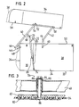
- Fig. 1 eine perspektivische Darstellung eines Pferdetrans wagens mit einer Hubeinrichtung, das Dach befindet sich in der normalen Schließposition,
- Fig. 2 eine Prinzipdarstellung einer Seitenansicht des Pferdetransportwagens gemäß Figur 1 bei angehobenem Dach und
- Fig. 3 ein Schnittbild durch das Gelenk einer vorderen Schwinge am Dach.
- Fig. 1 is a perspective view of a horse trans car with a lifting device, the roof is in the normal closed position,
- Fig. 2 is a schematic representation of a side view of the horse transport vehicle according to Figure 1 with the roof raised and
- Fig. 3 is a sectional view through the joint of a front swing arm on the roof.
Der in Figur 1 perspektivisch dargestellte Pferdetransportanhänger hat einen wannenartigen, auf einem zweiachsigen Fahrgestell 20 montierten Unterbau 22, der aus einem Boden, einer linken Seitenwand 24, einer Frontwand 26 und einer Rückwand aufgebaut ist. In letzterer ist eine - in den Figuren nicht dargestellte - Tür bekannten Art vorgesehen, durch die ein Pferd in den Innenraum des Pferdetransportanhängers eintreten und aus ihm heraustreten kann. Diese Teile sind jedoch gegenüber dem vorbekannten Pferdetransportanhänger ungeändert, so daß auf sie nicht im einzelnen eingegangen werden muß. Die Seitenwand 24 besteht aus einem längeren, in Fahrtrichtung verlaufenden hinteren Seitenwandteil 28 und einem kürzen vorderen Seitenwandteil 30, das schräg zur Fahrtrichtung angestellt ist und in dem eine kleine Tür 32 vorgesehen ist. Bis auf diese Tür 32 ist der Pferdetransportanhänger in Längsrichtung klappsymmetrisch.The horse transport trailer shown in perspective in FIG. 1 has a trough-
An die geschlossen umlaufende Oberkante des Unterbaues 22 ist ein wannenförmiges Dach 34 angesetzt, das den Unterbau 22 nach oben hin regendicht abschließt. Auch das Dach ist gegenüber dem vorbekannten Pferdetransportwagen ungeändert, so daß auf die Ausbildung des Daches im einzelnen nicht ein gegangen werden muß. In bevorzugter Weise ist das Dach eine Kunststoffschale, insbesondere Polyesterschale, die in geeigneter Weise armiert ist. Insgesamt hat das schalenförmige Dach 34 aufgrund seiner Wannenform eine hohe Eigensteifigkeit.A trough-
Bei dem in den Figuren 1 und 2 gezeigten Pferdetransportanhänger ist die vordere Frontwand 26 eben, sie steht senkrecht und verläuft 90° zur Fahrtrichtung. Bei anderen Pferdetransportanhängern ist diese Frontwand 26 bogenförmig ausgeführt, sie schmiegt sich in den Schrägverlauf des vorderen Seitenwandteils 30 tangential ein. Dieses geht auch nicht in einer Knickstelle in das hintere Seitenwandteil 28, sondern in einer Rundung in dieses über. Für derartige Pfertetransportanhänger ist der Verlauf der Vorderkante in Figur 2 gestrichelt dargestellt, die Vorderkante hat die Bezugsziffer 36. Das Dach in in seinem Frontbereich dem bogenförmigen Verlauf der Frontwand 26 angepaßt, dies ist durch die Dachvorderkante 38 in Figur 2 gestrichelt angedeutet.In the horse transport trailer shown in Figures 1 and 2, the
Zwischen dem Unterbau 22 und dem Dach 34 ist eine Hubeinrichtung angeordnet, die im folgenden näher erläutert wird: Das Dach 24 ist auf beiden Seiten des Unterbaues 22 jeweils über eine vordere Schwinge 40 und eine hintere Schwinge 42 am Unterbau 22 angelenkt. Die vorderen Schwingen 40 beider Seiten sind starr und - wie im gezeigten Ausführungsbeispiel - vorzugsweise einstückig miteinander verbunden. Die vorderen Schwingen 40 bilden dabei jeweils die Schenkel eines U-förmigen Bügels, dessen Basis 44 parallel zur Frontwand 26 verläuft. Jede vordere Schwinge 40 bzw. jeder Schenkel des U-Bügels verläuft ausgehend von der Basis 44 zunächst parallel zum zugehörigen, schräg verlaufenden Seiten wandteil 24, also divergierend und anschließend, im Bereich des Überganges zwischen vorderem Seitenwandteil 30 und hinterem Seitenwandteil 28 parallel zum hinteren Seitenwandteil 28, in diesem Bereich verlaufen die entsprechenden Teile der vorderen Schwingen beider Seiten parallel zueinander. Die vorderen Schwingen 40 sind nicht direkt, sondern über einen kurzen, senkrecht nach unten weisenden Arm 46 am Unterbau 26 in einem Gelenk 48 getragen. Der Ort dieses Gelenkes 48 soll möglichst weit vorn liegen, aus den Figuren 1 und 2 ist ersichtlich, daß das Gelenk praktisch in Höhe der ebenen Frontwand 26 liegt. Das Gelenk 48 liegt weiterhin um die Länge des Armes 46 unterhalb der Oberkante 50 des Unterbaues 22. Der Verbindungsbereich der vorderen Schwingen 40 mit ihrem jeweiligen Arm 46 ist etwa gleich weit von der Basis 44 des U-Bügels wie vom Gelenk 48 entfernt. Aufgrund der Anordnung des Gelenks 48 am unteren Ende des Arms 46 behält die Basis 44 des U-Bügels eine ausreichende Entfernung von der Frontwand 26, wenn die vorderen Schwingen 40, wie in Figur 2 dargestellt, hochgeschwenkt sind. Dies hat besondere Vorteile für die oben beschriebenen Pferdetransportanhänger mit gewölbter Frontwand 26, also der gestrichelt eingezeichneten Vorderkante 36. Wie Figur 2 zeigt, bleibt auch in dieser Ausführung ein ausreichender Freiraum zwischen der Vorderkante 36 und der Basis 44 des U-Bügels. Wäre die Hubeinrichtung lediglich für Transportwagen mit ebener Frontwand 26 ausgelegt, so könnte auf einen Arm 46 gänzlich verzichtet und das Gelenk 48 unmittelbar an der vorderen Schwinge 40 und beispielsweise im jetzigen Verbindungsbereich dieser vorderen Schwinge 40 mit dem Arm 46 angeordnet werden.A lifting device is arranged between the
An ihren freien Endbereichen sind die vorderen Schwingen 40 mit einer Abschrägung 52 versehen, auf die später noch eingegangen wird, und in Nähe dieser Abschrägung 52 in einem Gelenk 54 am Dach 34 angelenkt. Der Gelenkpunkt 54 befindet sich sehr nah der Unterkante 56 des Daches 34 und etwa lotrecht unterhalb des Massenmittelpunktes des Daches 34. Die effektive Länge der beiden (gleichlangen) vorderen Schwingen 40, also der Abstand der Gelenkpunkte 48, 54 entspricht etwa der Höhe des Unterbaues 22.At their free end regions, the
Die effektive Länge der beiden ebenfalls gleichlangen hinteren Schwingen beider Seiten beträgt etwa nur 85 bis 90 Prozent der genannten effektiven Länge der vorderen Schwingen 40, wodurch das die Hubeinrichtung bildende Gelenkviereck geringfügig von einem echten Parallelogramm abweicht. Die hinteren Schwingen 42 sind (beidseitig) jeweils in einem Gelenk 58 mit dem Dach 34 verbunden und in ihrem anderen Endbereich in einem Gelenk 60 am Unterbau 22, und zwar am hinteren Seitenwandteil 28 getragen. Die Gelenkpunkte 48, 54, 58 und 60 bilden das beschriebene Gelenkviereck. Der Gelenkpunkt 60 befindet sich etwas vor der Hälfte der Gesamtlänge des Unterbaues 22 und in derselben Höhe wie das Gelenk 48. Zwischen den am Dach 34 befindlichen Gelenken 54, 58 ist das Dach 34 beidseitig durch eine Versteifungsleiste 62 verstärkt, die geringfügig über die Gelenkpunkte 54, 58 seitlich hinausreicht. Sie ist bei vollständig geschlossenem Dach 34 in der Seitenperspektive praktisch vollstänig durch die Schwingen 40, 42 optisch verdeckt.The effective length of the two rear wings, which are also of equal length, on both sides is approximately only 85 to 90 percent of the effective length of the
Die hinteren Schwingen 42 haben in ihrem unteren Drittel eine Abwinklung 64 um etwa 30°. Dadurch verläuft ihr oberer Bereich in der in Figur 2 gezeigten angehobenen Position praktisch parallel zu den vorderen Schwingen 40, während der untere Bereich fast vertikal verläuft. Durch die Abwinklung 64 wird erreicht, daß der längere obere Bereich in der Schließposition des Daches 34 (siehe Fig. 1) parallel zu den Kanten 50, 56 und damit zur Trennebene von Dach 34 und Unterbau 22 verläuft. Die Abschrägung 52 verläuft dann parallel zum unteren Teilstück der hinteren Schwingen 42, wobei nur ein geringer Zwischenraum freibleibt. Optisch wird hierdurch in der Schließposition der Eindruck erweckt, als verlängerten die oberen Teile der hinteren Schwingen 42 die vorderen Schwingen 40. Wie Figur 1 zeigt, liegt auch der die vorderen Schwingen 40 ausbildende U-Bügel in der Schließposition über der Trennebene zwischen Dach 34 und Unterbau 22 und verdeckt die Kanten 50, 56.The
In der Schließposition wird das Dach 34 am Unterbau 22 über eine Anzahl von Spannschlössern 66, beispielsweise vier Stück, festgezurrt. Andere Befestigungsmittel, wie z. B. die von älteren Kraftfahrzeugen bekannten Gummizuglaschen, sind möglich.In the closed position, the
An der in den Figuren 1 und 2 dargestellten linken Seitenwand 24 ist an der dortigen vorderen Schwinge 40 in Nähe ihrer Abwinklung, jedoch im Bereich des in Fahrtrichtung verlaufenden hinteren Seitenwandteils 28 ein zweiter Arm 68 angesetzt, der wie die ersten Arme um eine Strecke von etwa 18 cm rechtwinklig nach unten vorspringt. An seinem unteren, freien Ende ist der in einem Gelenk 70 mit einer Teleskopstange 72 gelenkverbunden, die an ihrem unteren Endbereich in Höhe des Bodens des Unterbaues 22 im vordersten, untersten Eckbereich des vorderen linken Seitenwandteils 30 in einem Gelenk 74 getragen ist. In der normalen Schließposition steht diese Teleskopstange 72 vertikal, zugleich ligen die Gelenkpunkte 48, 60 und 70 in gleicher Höhe.On the
Die Teleskopstange 72 ist aus zwei konzentrischen Rohren, einem Außenrohr 76 und einem Innenrohr 78, aufgebaut, die ineinander geführt sind und durch eine innenliegende Schraubendruckfeder (nicht dargestellt) in Auszugsrichtung gegeneinander vorgespannt. Am unteren Endbereich des Außenrohrs 76 ist ein Klemmhebel 80 vorgesehen, wie er auch zur Verlängerung von Stielen von Fensterputzgeräten bekannt ist. Er ermöglicht eine reibschlüssige Arretierung des Außenrohrs 76 zum Innenrohr 78 in jeder beliebigen Position zwischen der normalen Schließposition und der maximalen Öffnungsstellung. Anstelle des verwendeten Klemmhebels 80 kann auch eine andere, beispielsweise formschlüssige Arretiervorrichtung Verwendung finden, hierzu müssen im Innenrohr 78 Einprägungen in gewissem Abstand vorgesehen sein, in die ein Schließteil der Arretiervorrichtung federbelastet eingreifen kann. Andere Ausbildungen sind möglich.The
Die beschriebene, in der Teleskopstange 72 untergebrachte, relativ lange Schraubendruckfeder ist kraftmäßig so bemessen, daß sie das Gewicht des ganzen Daches einschließlich der anteiligen Gewichte der bewegbaren Teile der Hubeinrichtung aufnimmt. Vorzugsweise ist sie sogar etwas kräftiger eingestellt als der genannte Wert. Beim Lösen des Klemmhebels 80 steigt dadurch das Dach selbsttätig in die in Figur 2 gezeigte angehobene Position, durch geringen Zug von wenigen Kilogramm am Außenrohr 76 kann das Dach 34 wieder heruntergeholt und in die normale Schließposition gebracht werden.The described, relatively long helical compression spring accommodated in the
Auf diese Weise können zwischen der maximalen Öffnungsstellung und der Schließposition beliebige Zwischenstellungen einge nommen werden. Dies hat beispielsweise den Vorteil, daß das Dach 34 geringfügig angehoben werden kann, wenn der Pferdetransportanhänger nicht bewegt wird und sich ein Pferd in ihm befindet. Dadurch erhält das Pferd Frischluft.In this way, any intermediate positions can be inserted between the maximum open position and the closed position be taken. This has the advantage, for example, that the
Die beschriebene Teleskopstange 72 ist lediglich ein Ausführungsbeispiel für einen vorteilhaften (grundsätzlich aber nicht notwendigen) Gewichtsausgleich der Hupeinrichtung. Anstelle der beschriebenen Teleskopstange 72 kann auch eine Gasdruckfeder, ein Öldruckstoßdämpfer mit Energiespeicher oder dergleichen Verwendung finden. Auch der Ort der Teleskopstange 72 ist grundsätzlich beliebig, beispielsweise kann auch parallel zur Frontwand 26 eine Zugfeder zwischen der Basis 44 und einem unteren Bereich der Frontwand 26 angeordnet sein.The
In Figur 3 ist schließlich die konstruktive Ausbildung eines Gelenks 54 erläutert, analog sind auch die Gelenke 58 ausgebildet. Der Innenraum des Pferdetransportwagens ist in Figur 3 unten. Bündig abschließend mit der Unterkante 56 des Daches 34 ist eine sehr flache innere Aussteifungsleiste 82 vorgesehen, die im wesentlichen einem ausreißsicheren Halt für Befestigungsmittel des Daches 34 dient. Diese Befestigungsmittel sind im gezeigten Ausführungsbeispiel als Senkschrauben ausgeführt. An der Außenseite befindet sich die bereits beschriebene Versteifungsleiste 62, so daß beide Versteifungsleisten 62, 82 das Dach 34 zwischen sich einspannen.Finally, the structural design of a joint 54 is explained in FIG. 3; the joints 58 are also designed analogously. The interior of the horse-drawn wagon is shown in Figure 3 below. Finally, flush with the
Das Gelenk 48 selbst ist wie folgt aufgebaut: Durch eine Bohrung in der Versteifungsleiste 62 greift eine Schraube 84, auf der Innenseite des Daches 34 ist eine Mutter 86 aufgeschraubt. Die Schraube spannt eine Hülse 88, die sie gegen die Versteifungsleiste 62 zieht. In die vordere Schwinge 40 ist eine Lagerbuchse 90 eingesetzt (eingeschweißt), zwischen ihr und der Hülse 88 ist ein Lagergeflecht vorgesehen, um die Gelenkpunkte völlig warungsfrei zu machen.The joint 48 itself is constructed as follows: a
Der die beiden vorderen Schwingen 40 ausbildende U-Bügel und die beiden hinteren Schwingen 42 sind aus stabilem Vierkantrohr in Aluminium oder Stahl gefertigt, beispielsweise ein Aluminiumrohr 40 x 60 x 2,5.The U-bracket forming the two
An der Unterkante 56 des Daches 34 oder der Oberkante 50 des Unterbaues 22 kann eine elastische Gummidichtung, beispielsweise eine aus dem Kraftfahrzeugbereich bekannte Lippendichtung oder eine Moosgummidichtung vorgesehen sein, um die Abdichtung zwischen Dach 34 und Unterbau zu verbessern.On the
In der in Figur 2 angehobenen Position befindet sich die Vorderkante des Daches 34 vor der Frontwand 26. Vorn ist zwischen der Oberkante 50 des Unterbaues 22 und der Unterkante 56 des Daches 54 ein Freiraum mit einer Höhe größer als ein Meter frei, unter der hinteren Kante des Daches 34 beträgt der Freiraum etwa 80 cm.In the position raised in FIG. 2, the front edge of the
Claims (12)
Applications Claiming Priority (2)
| Application Number | Priority Date | Filing Date | Title |
|---|---|---|---|
| DE3538196 | 1985-10-26 | ||
| DE19853538196 DE3538196A1 (en) | 1985-10-26 | 1985-10-26 | HORSE TRANSPORT CARTS, IN PARTICULAR TRAILERS |
Publications (2)
| Publication Number | Publication Date |
|---|---|
| EP0220627A2 true EP0220627A2 (en) | 1987-05-06 |
| EP0220627A3 EP0220627A3 (en) | 1989-03-29 |
Family
ID=6284584
Family Applications (1)
| Application Number | Title | Priority Date | Filing Date |
|---|---|---|---|
| EP86114400A Withdrawn EP0220627A3 (en) | 1985-10-26 | 1986-10-17 | Horse-transporting vehicle, in particular a trailer |
Country Status (3)
| Country | Link |
|---|---|
| US (1) | US4732419A (en) |
| EP (1) | EP0220627A3 (en) |
| DE (1) | DE3538196A1 (en) |
Cited By (1)
| Publication number | Priority date | Publication date | Assignee | Title |
|---|---|---|---|---|
| FR2725682A1 (en) * | 1994-10-17 | 1996-04-19 | Attard Jean Yves | Trailer for closed vehicle e.g. caravan or van |
Families Citing this family (6)
| Publication number | Priority date | Publication date | Assignee | Title |
|---|---|---|---|---|
| US5513595A (en) * | 1992-01-07 | 1996-05-07 | J. R. Floats Pty. Ltd. | Transportable animal enclosures |
| DE10052437B4 (en) * | 2000-10-23 | 2009-06-18 | Bpw Bergische Achsen Kg | Adjustable brace |
| US6755155B2 (en) * | 2002-06-24 | 2004-06-29 | Nancy May | Horse trailer |
| GB0221128D0 (en) * | 2002-09-12 | 2002-10-23 | Francis Robert | Trailers |
| US7124711B1 (en) * | 2004-12-02 | 2006-10-24 | Bearden Paul D | Gate closing apparatus |
| US20080073937A1 (en) * | 2006-09-25 | 2008-03-27 | Loran A. Circle | Trailer with access hatch |
Citations (4)
| Publication number | Priority date | Publication date | Assignee | Title |
|---|---|---|---|---|
| GB474864A (en) * | 1936-12-02 | 1937-11-09 | J H Jennings & Son Ltd | Improvements in vehicles for the road transport of horses and other animals |
| US3053224A (en) * | 1960-04-19 | 1962-09-11 | Hartman Trailer Mfg Company In | Horse trailer |
| FR1479272A (en) * | 1965-12-21 | 1967-05-05 | Trailer for road transport of a horse | |
| US3924889A (en) * | 1974-02-27 | 1975-12-09 | Michael Gogush | Elevating mechanism for the roofs or tops of vans and the like |
Family Cites Families (4)
| Publication number | Priority date | Publication date | Assignee | Title |
|---|---|---|---|---|
| US2531140A (en) * | 1948-02-13 | 1950-11-21 | Chance Co Ab | Trailer vehicle for hot line tools |
| US2963313A (en) * | 1959-05-22 | 1960-12-06 | James H Bennett | Travel trailer |
| DE7933410U1 (en) * | 1979-11-27 | 1980-06-04 | Arau, Jaime, Dipl.-Ing., 7054 Korb | Closed vehicle transport trailer |
| US4613181A (en) * | 1985-11-25 | 1986-09-23 | Rafi Zadeh Hassan | Cover assembly for pickup truck bed |
-
1985
- 1985-10-26 DE DE19853538196 patent/DE3538196A1/en not_active Withdrawn
-
1986
- 1986-10-17 EP EP86114400A patent/EP0220627A3/en not_active Withdrawn
- 1986-10-24 US US06/922,854 patent/US4732419A/en not_active Expired - Fee Related
Patent Citations (4)
| Publication number | Priority date | Publication date | Assignee | Title |
|---|---|---|---|---|
| GB474864A (en) * | 1936-12-02 | 1937-11-09 | J H Jennings & Son Ltd | Improvements in vehicles for the road transport of horses and other animals |
| US3053224A (en) * | 1960-04-19 | 1962-09-11 | Hartman Trailer Mfg Company In | Horse trailer |
| FR1479272A (en) * | 1965-12-21 | 1967-05-05 | Trailer for road transport of a horse | |
| US3924889A (en) * | 1974-02-27 | 1975-12-09 | Michael Gogush | Elevating mechanism for the roofs or tops of vans and the like |
Cited By (1)
| Publication number | Priority date | Publication date | Assignee | Title |
|---|---|---|---|---|
| FR2725682A1 (en) * | 1994-10-17 | 1996-04-19 | Attard Jean Yves | Trailer for closed vehicle e.g. caravan or van |
Also Published As
| Publication number | Publication date |
|---|---|
| EP0220627A3 (en) | 1989-03-29 |
| DE3538196A1 (en) | 1987-04-30 |
| US4732419A (en) | 1988-03-22 |
Similar Documents
| Publication | Publication Date | Title |
|---|---|---|
| DE2018319C3 (en) | Rear closure for opening the load compartment of a station wagon | |
| DE2739415C2 (en) | Sleeping facilities in long-haul cabs for trucks with built-in caravans | |
| DE19513520C1 (en) | Tailgate for multipurpose motor vehicle or estate car | |
| DE3200792A1 (en) | "VEHICLE TRAILER" | |
| DE102019107788A1 (en) | Openable construction for a substructure | |
| DE4011315A1 (en) | HOLDING DEVICE FOR VEHICLE REAR LOADS | |
| DE19731324A1 (en) | Extendable loading floor for a vehicle | |
| CH670224A5 (en) | ||
| EP0220627A2 (en) | Horse-transporting vehicle, in particular a trailer | |
| DE3531394A1 (en) | Camper with pull-out extension bunk | |
| DE3837252A1 (en) | Motor vehicle, in particular passenger vehicle (car), with a rear part which can be changed in its length | |
| DE2710141A1 (en) | Tailgate for commercial vehicle - has cable system to open upper section with spring loaded hooked rod acting as buffer | |
| DE102018107328B3 (en) | Openable construction for a substructure | |
| AT394832B (en) | BOX-LIKE CONSTRUCTION FOR A TRUCK | |
| DE102010045356A1 (en) | Load carrier with a swiveling sliding bearing | |
| DE60033900T2 (en) | Guide for a movable cover and movable cover using such a guide | |
| DE1803913C2 (en) | Device for opening and closing a cable car cabin | |
| DE3437848A1 (en) | TRAILER WITH CAB | |
| CH656917A5 (en) | SUPPORT AND GUIDE DEVICE FOR A SLIDING WALL. | |
| DE4201215C1 (en) | ||
| EP0825050A1 (en) | Stanchion between an upper boom and the platform frame of a vehicle | |
| DE1804953C3 (en) | Multi-level entry for vehicles, in particular rail vehicles, located in the vehicle profile | |
| EP0777986B1 (en) | Food service cart | |
| DE2708453A1 (en) | BODY CONSTRUCTION OF VEHICLES WITH AT LEAST ONE SLIDING DOOR | |
| DE202014100949U1 (en) | Commercial vehicle with at least one side tarpaulin |
Legal Events
| Date | Code | Title | Description |
|---|---|---|---|
| PUAI | Public reference made under article 153(3) epc to a published international application that has entered the european phase |
Free format text: ORIGINAL CODE: 0009012 |
|
| AK | Designated contracting states |
Kind code of ref document: A2 Designated state(s): AT BE CH DE ES FR GB IT LI LU NL SE |
|
| PUAL | Search report despatched |
Free format text: ORIGINAL CODE: 0009013 |
|
| AK | Designated contracting states |
Kind code of ref document: A3 Designated state(s): AT BE CH DE ES FR GB IT LI LU NL SE |
|
| STAA | Information on the status of an ep patent application or granted ep patent |
Free format text: STATUS: THE APPLICATION IS DEEMED TO BE WITHDRAWN |
|
| 18D | Application deemed to be withdrawn |
Effective date: 19890930 |
|
| RIN1 | Information on inventor provided before grant (corrected) |
Inventor name: KETTERER, MICHAEL Inventor name: MEROTH, ERWIN |