EP0219362B1 - Verriegelbare Gasfeder - Google Patents
Verriegelbare Gasfeder Download PDFInfo
- Publication number
- EP0219362B1 EP0219362B1 EP86401748A EP86401748A EP0219362B1 EP 0219362 B1 EP0219362 B1 EP 0219362B1 EP 86401748 A EP86401748 A EP 86401748A EP 86401748 A EP86401748 A EP 86401748A EP 0219362 B1 EP0219362 B1 EP 0219362B1
- Authority
- EP
- European Patent Office
- Prior art keywords
- pneumatic spring
- slide
- cylindrical
- diameter
- rod
- Prior art date
- Legal status (The legal status is an assumption and is not a legal conclusion. Google has not performed a legal analysis and makes no representation as to the accuracy of the status listed.)
- Expired
Links
- 238000004891 communication Methods 0.000 claims description 6
- 230000000694 effects Effects 0.000 claims description 2
- 229910000831 Steel Inorganic materials 0.000 description 3
- 238000003754 machining Methods 0.000 description 3
- 238000000465 moulding Methods 0.000 description 3
- 238000007789 sealing Methods 0.000 description 3
- 239000010959 steel Substances 0.000 description 3
- 238000002788 crimping Methods 0.000 description 2
- 239000011159 matrix material Substances 0.000 description 2
- 125000006850 spacer group Chemical group 0.000 description 2
- 238000009987 spinning Methods 0.000 description 2
- 230000000295 complement effect Effects 0.000 description 1
- 238000006073 displacement reaction Methods 0.000 description 1
- 238000002347 injection Methods 0.000 description 1
- 239000007924 injection Substances 0.000 description 1
- 239000007788 liquid Substances 0.000 description 1
- 238000012423 maintenance Methods 0.000 description 1
- 239000000463 material Substances 0.000 description 1
- 238000000034 method Methods 0.000 description 1
- 238000003825 pressing Methods 0.000 description 1
Images

Classifications
-
- A—HUMAN NECESSITIES
- A47—FURNITURE; DOMESTIC ARTICLES OR APPLIANCES; COFFEE MILLS; SPICE MILLS; SUCTION CLEANERS IN GENERAL
- A47C—CHAIRS; SOFAS; BEDS
- A47C3/00—Chairs characterised by structural features; Chairs or stools with rotatable or vertically-adjustable seats
- A47C3/20—Chairs or stools with vertically-adjustable seats
- A47C3/30—Chairs or stools with vertically-adjustable seats with vertically-acting fluid cylinder
-
- A—HUMAN NECESSITIES
- A47—FURNITURE; DOMESTIC ARTICLES OR APPLIANCES; COFFEE MILLS; SPICE MILLS; SUCTION CLEANERS IN GENERAL
- A47B—TABLES; DESKS; OFFICE FURNITURE; CABINETS; DRAWERS; GENERAL DETAILS OF FURNITURE
- A47B9/00—Tables with tops of variable height
- A47B9/10—Tables with tops of variable height with vertically-acting fluid cylinder
-
- F—MECHANICAL ENGINEERING; LIGHTING; HEATING; WEAPONS; BLASTING
- F16—ENGINEERING ELEMENTS AND UNITS; GENERAL MEASURES FOR PRODUCING AND MAINTAINING EFFECTIVE FUNCTIONING OF MACHINES OR INSTALLATIONS; THERMAL INSULATION IN GENERAL
- F16F—SPRINGS; SHOCK-ABSORBERS; MEANS FOR DAMPING VIBRATION
- F16F9/00—Springs, vibration-dampers, shock-absorbers, or similarly-constructed movement-dampers using a fluid or the equivalent as damping medium
- F16F9/02—Springs, vibration-dampers, shock-absorbers, or similarly-constructed movement-dampers using a fluid or the equivalent as damping medium using gas only or vacuum
- F16F9/0209—Telescopic
- F16F9/0245—Means for adjusting the length of, or for locking, the spring or dampers
Definitions
- the present invention relates to pneumatic springs which are lockable in intermediate positions.
- These devices include, as we know, a piston sliding in a cylinder and separating it into two chambers isolated from each other but which can be made to communicate with each other, by means of a maneuverable valve, to modify the position of the piston, the movement of the latter being blocked when said communication is cut.
- valve consists of two concentric parts, mounted for rotation relative to each other, and having openings which can be opened or closed by the relative rotation of the parts.
- openings which can be opened or closed by the relative rotation of the parts.
- Patent FR-A-1 453 681 describes a valve formed of an axially movable cylindrical part, terminated by a conical part, which cooperates with the edges of an axial channel, which act as the seat of a needle valve.
- a needle valve, or valve that is to say a valve where the seal is obtained by cooperation of two surfaces of which one, at least, is conical or planar, is that a very small relative movement of the cooperating parts changes from opening to closing and vice versa. It is therefore necessary to provide means to ensure with certainty the maintenance of the valve in the desired condition, especially the closed condition. These means tend to develop a large force, which can deteriorate the sealing surfaces over time.
- drawer valves Another type of valve is known, called “drawer” valves where the seal is ensured by the radial contact between a cylindrical surface and another surface which has a substantially equal diameter and which can also be cylindrical.
- the opening of the valve is ensured by the fact that the diameter of one of the parts varies at the end of the cylindrical surface, to make room in general for a conical or planar surface, this conical or planar surface not being involved in obtaining the In such valves, a large displacement of the cylindrical surface has no significant consequence, as long as the end of this cylindrical surface remains away from the surface which cooperates with it, so that the holding means can tolerate significant axial movements and therefore do not require significant force.
- valve of this type in the form of a rod which can slide through two bottoms, facing one end of the cylinder and leaving a gap between them. where the communication between the two faces of the piston opens.
- bottoms are respectively provided with grooves for housing seals cooperating with the rod and the latter comprises between the seals an annular groove whose walls form a frustoconical flare towards the outside.
- a disadvantage of such an embodiment of the valve is that if it is to be manufactured by a molding process or by cold stamping, it is necessary to use a mold or a matrix in two pieces, which leave a trace of seal in front be removed by machining.
- the object of the invention is to make it simpler and more economical to produce lockable pneumatic springs, comprising a slide valve.
- the rod forming a drawer has a cross section whose variation is of constant sign when one goes from one end to the other of said rod, so that the latter which is devoid of groove can be produced by spinning or by molding or cold stamping in a mold or a die in one piece, which eliminates the need for a complementary machining operation.
- the rod or drawer consists of two cylindrical parts of different diameters, joined together by an intermediate surface in the form of a truncated cone, the small diameter part projecting outwards for the operation of the rod, while the part of larger diameter cooperates with a seal which, depending on the position of the rod, either prevents the passage of gas, being then clamped on the part of large diameter or allows passage when the part of the rod with small diameter comes to the level of this joint.
- Said seal as well as a second seal cooperating with the part of the rod with a small diameter, are arranged in the same piece forming the bottom common to the two concentric cylinders, an annular spacer being however provided between the seals to hold them axially.
- Another improvement consists in crimping the two tubes one on the other on the bottom of the device, with the interposition of a suitable seal.
- the inner tube which mainly supports the forces exerted by the pressure of the gas on the bottom and this tube is therefore made of high strength steel, while the outer tube can be made of a less resistant material.
- the large-diameter flange which terminates the drawer rod towards the interior of the apparatus is adjusted in a cylindrical housing of a part integral with the corresponding bottom, thereby providing additional guidance of the drawer rod which improves the lifespan of the device.
- grooves are formed on the cylindrical guide wall.
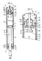
- the pneumatic spring comprises a first cylinder 1 in which a piston 2 can slide, provided with a seal 3 and integral with a rod 4 which projects at the outside the appliance.
- the cylinder 1 is closed by a cylindrical bottom 5 provided with a bearing surface 6 on which the cylinder 1 is fitted, an annular seal 7 ensuring the tightness of the fitting .
- the cylinder 1 is fitted onto a half-bottom 8 which is crossed by the rod 4 but which leaves a significant clearance 9 around the rod, the utility of which will be seen below.
- a second cylinder 10 Around the cylinder 1 is a second cylinder 10 whose internal radius is larger than the external radius of the cylinder 1 so that there is a gap 11 between the two cylinders.
- This outer cylinder is crimped at its end 12 on the bottom 5 with seal 13 and its other end 14 is also crimped on a bottom 15 which is crossed by the rod 4 and which maintains between it and the middle bottom 8 a lip seal washer 16.
- This seal the lip of which rests on the rod 4, seals the said rod in an arrangement well known in itself.
- This drawer has 3 cylindrical parts of different diameters 22, 23 and 24.
- the part 22 of relatively small diameter has the shape of a rod which protrudes towards the outside of the apparatus through the bottom 5 and which is used for maneuvering check the drawer for opening. It crosses a seal 25.
- the part 23 of larger diameter cooperates with a seal 26.
- the part 24 in the shape of a flat head has a diameter large enough to ensure that the valve closes when it is abandoned. to itself, under the effect of the gas pressure prevailing in the chamber 18, despite the back pressure of the gas arriving through the channel 20.
- the cylindrical parts 22 and 23 of the drawer are joined together by an intermediate part 29 of generally frustoconical or other shape with a straight profile, or concave or convex or even stepped.
- the drawer can therefore be obtained by spinning, by molding, for example by injection or by stamping or cold stamping, with a mold or a matrix in one piece, therefore leaving no trace on the drawer corresponding to a joint plane, rectification machining becoming superfluous, which is an important advantage for lowering the cost price.
- FIG. 2 the position of the valve is seen when it has been opened by pressing on the outer end of part 22.
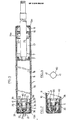
- a valve of similar characteristic can be used in lockable springs having constitutions different from that which has just been described with reference to FIG. 1.
- FIG. 3 for example, where only one of the ends of the air spring is shown, it is of the mono-cylindrical type.
- the chambers 17 and 18 separated by the piston 2 are connected together by the channel 30 drilled in the rod 4 and in the piston, and by the flexible helical pipe 31 which terminates in the channel 32 drilled in the drawer.
- the cylindrical parts 22, 23 connected to each other by the frustoconical part 29, and 24.
- valve is incorporated in the piston and the three cylindrical parts 22, 23 and 24 can also be recognized as well as the frustoconical part 29 interposed between the parts 22 and 23.
- the part 22, forming as above the control rod, is placed inside the rod 4 piston 2, at the end of which it projects for the operation.
- the tubes 1 and 10 which provide the gap 11 between them, are crimped one on the other on the bottoms 5 and 8 of the device, with interposition a sealing ring 13a which is crushed during crimping.
- the inner tube 1 thus maintains the bottoms 5 and 8 against the gas pressure and it is made of high-strength steel, while the outer tube 10, which only supports the force of the gas pressure in the annular interval 11 , may be of less resistant steel. Punctures, such as 35, formed in the inner tube 1, make it possible to communicate the interval 11 with the pipe 20 formed in the bottom 5.
- punctures 35a ensure the communication of the interval 11 with the chamber 17.
- the lips of these punctures also serve to hold in place a sleeve 36 applied against the elastic washer 16 of the lip seal ensuring the sealing on the rod of piston 4.
- Longitudinal slots 37, formed in the sleeve 36 in line with the punctures 35a, allow the passage of gas.
- a constriction 38 of the tube 1 serves to hold the base 5 in place.
- the latter is completed by an annular piece 39, of a certain thickness, which may be made of plastic and in which a cylindrical housing 40 adjusted to the large diameter flange 24 of the drawer rod. In this way, this flange is guided in the housing 40 when the rod-drawer moves, the guidance of which is thus improved.
- the length of the generator of the cylindrical housing 40 is sufficient so that in the final open position of the spool, shown in FIG. 7, the flange 24 is still in the housing 40.
- grooves 41 are formed on the wall of the housing 40.
Landscapes
- Engineering & Computer Science (AREA)
- General Engineering & Computer Science (AREA)
- Mechanical Engineering (AREA)
- Fluid-Damping Devices (AREA)
- Percussive Tools And Related Accessories (AREA)
- Vibration Prevention Devices (AREA)
- Pipe Accessories (AREA)
- Medicines Containing Plant Substances (AREA)
- Orthopedics, Nursing, And Contraception (AREA)
Claims (8)
Priority Applications (1)
| Application Number | Priority Date | Filing Date | Title |
|---|---|---|---|
| AT86401748T ATE42619T1 (de) | 1985-08-28 | 1986-08-05 | Verriegelbare gasfeder. |
Applications Claiming Priority (2)
| Application Number | Priority Date | Filing Date | Title |
|---|---|---|---|
| FR8512836 | 1985-08-28 | ||
| FR8512836A FR2586771B1 (fr) | 1985-08-28 | 1985-08-28 | Ressort pneumatique blocable |
Publications (3)
| Publication Number | Publication Date |
|---|---|
| EP0219362A1 EP0219362A1 (de) | 1987-04-22 |
| EP0219362B1 true EP0219362B1 (de) | 1989-04-26 |
| EP0219362B2 EP0219362B2 (de) | 1992-07-29 |
Family
ID=9322455
Family Applications (1)
| Application Number | Title | Priority Date | Filing Date |
|---|---|---|---|
| EP86401748A Expired - Lifetime EP0219362B2 (de) | 1985-08-28 | 1986-08-05 | Verriegelbare Gasfeder |
Country Status (7)
| Country | Link |
|---|---|
| US (1) | US4871149A (de) |
| EP (1) | EP0219362B2 (de) |
| AT (1) | ATE42619T1 (de) |
| BR (1) | BR8604107A (de) |
| DE (1) | DE3663075D1 (de) |
| ES (1) | ES2001404A6 (de) |
| FR (1) | FR2586771B1 (de) |
Families Citing this family (20)
| Publication number | Priority date | Publication date | Assignee | Title |
|---|---|---|---|---|
| DE3615688A1 (de) * | 1986-05-09 | 1987-11-12 | Bauer Fritz & Soehne Ohg | Laengenverstellbare gasfeder und betaetigungseinrichtung hierfuer |
| DE8710208U1 (de) * | 1987-07-25 | 1988-11-24 | Fritz Bauer + Söhne oHG, 8503 Altdorf | Fluidgefüllte Kolben-Zylinder-Einheit |
| US4834347A (en) * | 1988-04-20 | 1989-05-30 | Grazina J. Pauliukonis | Positioner with large diameter piston rod and fluted volume-compensating piston |
| DE3825076A1 (de) * | 1988-07-23 | 1990-01-25 | Bauer Fritz & Soehne Ohg | Laengeneinstellbare verstelleinrichtung |
| DE3904585A1 (de) * | 1989-02-16 | 1990-08-23 | Stabilus Gmbh | Blockierventil fuer eine gasfeder |
| EP0422888A3 (en) * | 1989-10-11 | 1992-02-26 | Fuji Photo Film Co., Ltd. | An electrophotographic lithographic printing plate precursor |
| DE4009035A1 (de) * | 1990-03-21 | 1991-09-26 | Suspa Federungstech | Laengenverstellbare gasfeder |
| JP3062961B2 (ja) | 1991-03-15 | 2000-07-12 | トキコ株式会社 | ロック付ガススプリング |
| IL98036A0 (en) * | 1991-05-02 | 1992-06-21 | Yoav Cohen | Plastic stand pipe support for load-bearing adjustable piston |
| US5516082A (en) * | 1993-06-25 | 1996-05-14 | Talleres Gain, S. Coop. S.L. | Gas cylinder |
| US5362034A (en) * | 1993-08-26 | 1994-11-08 | Chia-Hsiung Chen | Hydraulic height adjusting device |
| DE4420914A1 (de) * | 1994-06-16 | 1995-12-21 | Suspa Compart Ag | Längenverstellbare Gasfeder und längenverstellbare Säule für Stühle, Tische mit einer längenverstellbaren Gasfeder |
| WO2001033102A1 (es) * | 1999-11-04 | 2001-05-10 | Gain Gas Technique, S.L. | Amortiguador a gas |
| RU2201543C2 (ru) * | 2000-12-28 | 2003-03-27 | Закрытое акционерное общество Научно-производственный центр информационных и транспортных систем | Тросовый виброизолятор |
| US7108324B2 (en) * | 2002-06-28 | 2006-09-19 | Lear Corporation | Vehicle seat adjuster |
| DE102004023335A1 (de) * | 2004-01-24 | 2005-08-11 | Suspa Holding Gmbh | Höhenverstellbare Stuhl-Säule |
| MX2010003140A (es) * | 2007-09-20 | 2010-06-02 | Miller Herman Inc | Estructura de soporte de cuerpo. |
| US20090315376A1 (en) * | 2008-06-19 | 2009-12-24 | Takuro Nishiwaki | Reclinable chair with adjustable parallel locking gas spring device |
| US8091481B1 (en) * | 2009-05-01 | 2012-01-10 | Floyd Brian A | Gas strut separation for staged rocket |
| US11486377B1 (en) * | 2021-07-09 | 2022-11-01 | Scott Wu | Quickly assembled air pump comprising a cylinder with a retaining hold adjacent to an opening for a position rod wherein a retaining portion of an upper cover is engaged with the retaining hole and a conical lateral face of a piston is selectively abutted against an extension portion of the upper cover |
Family Cites Families (14)
| Publication number | Priority date | Publication date | Assignee | Title |
|---|---|---|---|---|
| US2336924A (en) * | 1942-10-15 | 1943-12-14 | Cordis Nat | Bottle discharging means |
| US3024067A (en) * | 1959-10-12 | 1962-03-06 | Brandoli Marino | Seat having adjustable back |
| DE1812282C3 (de) * | 1968-12-03 | 1981-07-30 | Fritz Bauer + Söhne oHG, 8503 Altdorf | Hubvorrichtung zum stufenlosen Höhenverstellen von Tischplatten, Stuhlsitzen u.dgl. |
| DE1931494A1 (de) * | 1969-06-20 | 1971-02-04 | Stiegelmeyer & Co Gmbh | Stufenlose Verstelleinrichtung |
| DE1951656C3 (de) * | 1969-10-14 | 1973-10-04 | Ignaz Vogel Kg, 7501 Stupferich | Full und Betätigungseinrichtung für (hydro )pneumatische Federn |
| US3739885A (en) * | 1971-06-15 | 1973-06-19 | Automotive Prod Co Ltd | Telescopic position adjusting devices |
| DE2341352C2 (de) * | 1973-08-16 | 1983-10-06 | Stabilus Gmbh, 5400 Koblenz | Blockierbares Hubaggregat mit Endfederung |
| DE2459340C2 (de) * | 1974-12-16 | 1985-05-23 | Stabilus Gmbh, 5400 Koblenz | Stufenlos höhenverstellbare Säule |
| JPS52159313U (de) * | 1976-05-28 | 1977-12-03 | ||
| DE2638363A1 (de) * | 1976-08-26 | 1978-03-02 | Suspa Federungstech | Laengenverstellbare gasfeder |
| IT1136001B (it) * | 1980-05-15 | 1986-08-27 | Sergio Corti | Dispositivo di supporto e di regolazione in altezza del sedile di sedie o poltrone, del ripiano di tavoli e simili |
| DE3040483A1 (de) * | 1980-10-28 | 1982-06-16 | Stabilus Gmbh, 5400 Koblenz | Gasfeder mit hydraulischer blockierung |
| DE3125387A1 (de) * | 1981-06-27 | 1983-01-27 | Stabilus Gmbh, 5400 Koblenz | Pneumatisches oder hydropneumatisches aggregat mit fluessiggasfuellung |
| US4465266A (en) * | 1982-03-08 | 1984-08-14 | Hale Chairco Corporation | Power unit for medical and like stools and chairs |
-
1985
- 1985-08-28 FR FR8512836A patent/FR2586771B1/fr not_active Expired - Lifetime
-
1986
- 1986-08-05 AT AT86401748T patent/ATE42619T1/de not_active IP Right Cessation
- 1986-08-05 EP EP86401748A patent/EP0219362B2/de not_active Expired - Lifetime
- 1986-08-05 DE DE8686401748T patent/DE3663075D1/de not_active Expired
- 1986-08-27 ES ES8601412A patent/ES2001404A6/es not_active Expired
- 1986-08-28 BR BR8604107A patent/BR8604107A/pt not_active IP Right Cessation
-
1989
- 1989-04-26 US US07/344,528 patent/US4871149A/en not_active Expired - Lifetime
Also Published As
| Publication number | Publication date |
|---|---|
| US4871149A (en) | 1989-10-03 |
| EP0219362B2 (de) | 1992-07-29 |
| FR2586771A1 (fr) | 1987-03-06 |
| EP0219362A1 (de) | 1987-04-22 |
| BR8604107A (pt) | 1987-04-22 |
| ES2001404A6 (es) | 1988-05-16 |
| DE3663075D1 (en) | 1989-06-01 |
| ATE42619T1 (de) | 1989-05-15 |
| FR2586771B1 (fr) | 1990-02-02 |
Similar Documents
| Publication | Publication Date | Title |
|---|---|---|
| EP0219362B1 (de) | Verriegelbare Gasfeder | |
| EP0349377B1 (de) | Elektrisches Mikro-Umschaltventil mit einer einzigen Membran | |
| FR2810701A1 (fr) | Verin hydraulique a double effet avec dispositif de blocage axial | |
| FR2692569A1 (fr) | Procédé et dispositif de remplissage d'un distributeur doseur de substance fluide. | |
| EP0002144B1 (de) | Verbesserter Kolben für pneumatische oder derartige Federn | |
| LU86438A1 (fr) | Robinet a membrane | |
| FR2734039A1 (fr) | Valve perfectionnee pour dispositif de conditionnement et de distribution d'un produit stocke sous pression, dispositif ainsi equipe et procede de fabrication | |
| EP2780624A1 (de) | Gasflaschenventil mit einem schwungrad zur steuerung eines restdruckventils und eines sperrventils | |
| FR2594520A1 (fr) | Joint de bout de tige pour robinet d'arret | |
| FR2590343A1 (fr) | Dispositif actionne par fluide | |
| EP0847511A1 (de) | Schnellkupplung für druckleitungen | |
| EP0751083B1 (de) | Druckbehälterventil sowie mit einem solchen Ventil versehener Druckbehälter | |
| EP1802402B1 (de) | Sicherungsverfahren, herstellungsverfahren und sicheres sprayendstück | |
| EP0852548B1 (de) | Hauptzylinder mit vereinfachter einstellung | |
| EP0819076B1 (de) | Tandemhauptzylinder mit verbesserter abdichtung | |
| CH683792A5 (fr) | Dispositif de dosage micrométrique. | |
| FR2793223A1 (fr) | Pompe a membrane comportant, sur au moins un secteur de sa peripherie, une zone de deformation preferentielle et recipient ainsi equipe | |
| FR2507733A1 (fr) | Vanne a passage direct | |
| EP1503117A1 (de) | Ventil zur Entnahme eines begrentzten Gazvolumens aus einer Gazflasche | |
| FR2724441A1 (fr) | Vanne a clapet et membrane | |
| CH396396A (fr) | Installation de thermoformage | |
| FR2633695A2 (fr) | Microelectrovanne de commutation a une seule membrane | |
| FR2777610A1 (fr) | Distributeur commande par un tiroir | |
| FR2745353A1 (fr) | Dispositif d'etancheite pour vanne a tournant spherique | |
| EP0281834A2 (de) | Ventil für Druck- oder Flüssiggase |
Legal Events
| Date | Code | Title | Description |
|---|---|---|---|
| PUAI | Public reference made under article 153(3) epc to a published international application that has entered the european phase |
Free format text: ORIGINAL CODE: 0009012 |
|
| AK | Designated contracting states |
Kind code of ref document: A1 Designated state(s): AT BE CH DE FR GB IT LI LU NL SE |
|
| 17P | Request for examination filed |
Effective date: 19870916 |
|
| 17Q | First examination report despatched |
Effective date: 19880607 |
|
| GRAA | (expected) grant |
Free format text: ORIGINAL CODE: 0009210 |
|
| AK | Designated contracting states |
Kind code of ref document: B1 Designated state(s): AT BE CH DE FR GB IT LI LU NL SE |
|
| REF | Corresponds to: |
Ref document number: 42619 Country of ref document: AT Date of ref document: 19890515 Kind code of ref document: T |
|
| ITF | It: translation for a ep patent filed | ||
| GBT | Gb: translation of ep patent filed (gb section 77(6)(a)/1977) | ||
| REF | Corresponds to: |
Ref document number: 3663075 Country of ref document: DE Date of ref document: 19890601 |
|
| PLBI | Opposition filed |
Free format text: ORIGINAL CODE: 0009260 |
|
| 26 | Opposition filed |
Opponent name: FRITZ BAUER + SOEHNE OHG Effective date: 19891115 |
|
| NLR1 | Nl: opposition has been filed with the epo |
Opponent name: SOEHNE OHG Opponent name: FRITZ BAUER |
|
| ITTA | It: last paid annual fee | ||
| PUAH | Patent maintained in amended form |
Free format text: ORIGINAL CODE: 0009272 |
|
| STAA | Information on the status of an ep patent application or granted ep patent |
Free format text: STATUS: PATENT MAINTAINED AS AMENDED |
|
| 27A | Patent maintained in amended form |
Effective date: 19920729 |
|
| AK | Designated contracting states |
Kind code of ref document: B2 Designated state(s): AT BE CH DE FR GB IT LI LU NL SE |
|
| PGFP | Annual fee paid to national office [announced via postgrant information from national office to epo] |
Ref country code: AT Payment date: 19920813 Year of fee payment: 7 |
|
| PGFP | Annual fee paid to national office [announced via postgrant information from national office to epo] |
Ref country code: CH Payment date: 19920814 Year of fee payment: 7 |
|
| PGFP | Annual fee paid to national office [announced via postgrant information from national office to epo] |
Ref country code: SE Payment date: 19920817 Year of fee payment: 7 |
|
| ITF | It: translation for a ep patent filed | ||
| PGFP | Annual fee paid to national office [announced via postgrant information from national office to epo] |
Ref country code: NL Payment date: 19920831 Year of fee payment: 7 |
|
| PGFP | Annual fee paid to national office [announced via postgrant information from national office to epo] |
Ref country code: LU Payment date: 19920903 Year of fee payment: 7 |
|
| NLR2 | Nl: decision of opposition | ||
| PGFP | Annual fee paid to national office [announced via postgrant information from national office to epo] |
Ref country code: BE Payment date: 19920918 Year of fee payment: 7 |
|
| GBTA | Gb: translation of amended ep patent filed (gb section 77(6)(b)/1977) | ||
| NLR3 | Nl: receipt of modified translations in the netherlands language after an opposition procedure | ||
| EPTA | Lu: last paid annual fee | ||
| PG25 | Lapsed in a contracting state [announced via postgrant information from national office to epo] |
Ref country code: LU Free format text: LAPSE BECAUSE OF NON-PAYMENT OF DUE FEES Effective date: 19930805 Ref country code: AT Effective date: 19930805 |
|
| PG25 | Lapsed in a contracting state [announced via postgrant information from national office to epo] |
Ref country code: SE Effective date: 19930806 |
|
| PG25 | Lapsed in a contracting state [announced via postgrant information from national office to epo] |
Ref country code: LI Effective date: 19930831 Ref country code: CH Effective date: 19930831 Ref country code: BE Effective date: 19930831 |
|
| BERE | Be: lapsed |
Owner name: AIRAX Effective date: 19930831 |
|
| PG25 | Lapsed in a contracting state [announced via postgrant information from national office to epo] |
Ref country code: NL Effective date: 19940301 |
|
| NLV4 | Nl: lapsed or anulled due to non-payment of the annual fee | ||
| REG | Reference to a national code |
Ref country code: CH Ref legal event code: PL |
|
| EUG | Se: european patent has lapsed |
Ref document number: 86401748.8 Effective date: 19940310 |
|
| REG | Reference to a national code |
Ref country code: GB Ref legal event code: IF02 |
|
| PGFP | Annual fee paid to national office [announced via postgrant information from national office to epo] |
Ref country code: GB Payment date: 20030730 Year of fee payment: 18 |
|
| PGFP | Annual fee paid to national office [announced via postgrant information from national office to epo] |
Ref country code: FR Payment date: 20030808 Year of fee payment: 18 |
|
| PGFP | Annual fee paid to national office [announced via postgrant information from national office to epo] |
Ref country code: DE Payment date: 20030814 Year of fee payment: 18 |
|
| PG25 | Lapsed in a contracting state [announced via postgrant information from national office to epo] |
Ref country code: GB Free format text: LAPSE BECAUSE OF NON-PAYMENT OF DUE FEES Effective date: 20040805 |
|
| PG25 | Lapsed in a contracting state [announced via postgrant information from national office to epo] |
Ref country code: DE Free format text: LAPSE BECAUSE OF NON-PAYMENT OF DUE FEES Effective date: 20050301 |
|
| GBPC | Gb: european patent ceased through non-payment of renewal fee |
Effective date: 20040805 |
|
| PG25 | Lapsed in a contracting state [announced via postgrant information from national office to epo] |
Ref country code: FR Free format text: LAPSE BECAUSE OF NON-PAYMENT OF DUE FEES Effective date: 20050429 |
|
| REG | Reference to a national code |
Ref country code: FR Ref legal event code: ST |
|
| PG25 | Lapsed in a contracting state [announced via postgrant information from national office to epo] |
Ref country code: IT Free format text: LAPSE BECAUSE OF NON-PAYMENT OF DUE FEES;WARNING: LAPSES OF ITALIAN PATENTS WITH EFFECTIVE DATE BEFORE 2007 MAY HAVE OCCURRED AT ANY TIME BEFORE 2007. THE CORRECT EFFECTIVE DATE MAY BE DIFFERENT FROM THE ONE RECORDED. Effective date: 20050805 |