EP0219318A2 - Fernbedienbares Brennstoffschleusensystem für Kernreaktor - Google Patents
Fernbedienbares Brennstoffschleusensystem für Kernreaktor Download PDFInfo
- Publication number
- EP0219318A2 EP0219318A2 EP86307825A EP86307825A EP0219318A2 EP 0219318 A2 EP0219318 A2 EP 0219318A2 EP 86307825 A EP86307825 A EP 86307825A EP 86307825 A EP86307825 A EP 86307825A EP 0219318 A2 EP0219318 A2 EP 0219318A2
- Authority
- EP
- European Patent Office
- Prior art keywords
- drive screw
- segments
- fuel
- segment
- drive
- Prior art date
- Legal status (The legal status is an assumption and is not a legal conclusion. Google has not performed a legal analysis and makes no representation as to the accuracy of the status listed.)
- Withdrawn
Links
Images
Classifications
-
- G—PHYSICS
- G21—NUCLEAR PHYSICS; NUCLEAR ENGINEERING
- G21C—NUCLEAR REACTORS
- G21C19/00—Arrangements for treating, for handling, or for facilitating the handling of, fuel or other materials which are used within the reactor, e.g. within its pressure vessel
- G21C19/02—Details of handling arrangements
- G21C19/10—Lifting devices or pulling devices adapted for co-operation with fuel elements or with control elements
-
- G—PHYSICS
- G21—NUCLEAR PHYSICS; NUCLEAR ENGINEERING
- G21C—NUCLEAR REACTORS
- G21C19/00—Arrangements for treating, for handling, or for facilitating the handling of, fuel or other materials which are used within the reactor, e.g. within its pressure vessel
- G21C19/18—Apparatus for bringing fuel elements to the reactor charge area, e.g. from a storage place
-
- Y—GENERAL TAGGING OF NEW TECHNOLOGICAL DEVELOPMENTS; GENERAL TAGGING OF CROSS-SECTIONAL TECHNOLOGIES SPANNING OVER SEVERAL SECTIONS OF THE IPC; TECHNICAL SUBJECTS COVERED BY FORMER USPC CROSS-REFERENCE ART COLLECTIONS [XRACs] AND DIGESTS
- Y02—TECHNOLOGIES OR APPLICATIONS FOR MITIGATION OR ADAPTATION AGAINST CLIMATE CHANGE
- Y02E—REDUCTION OF GREENHOUSE GAS [GHG] EMISSIONS, RELATED TO ENERGY GENERATION, TRANSMISSION OR DISTRIBUTION
- Y02E30/00—Energy generation of nuclear origin
- Y02E30/30—Nuclear fission reactors
-
- Y—GENERAL TAGGING OF NEW TECHNOLOGICAL DEVELOPMENTS; GENERAL TAGGING OF CROSS-SECTIONAL TECHNOLOGIES SPANNING OVER SEVERAL SECTIONS OF THE IPC; TECHNICAL SUBJECTS COVERED BY FORMER USPC CROSS-REFERENCE ART COLLECTIONS [XRACs] AND DIGESTS
- Y10—TECHNICAL SUBJECTS COVERED BY FORMER USPC
- Y10T—TECHNICAL SUBJECTS COVERED BY FORMER US CLASSIFICATION
- Y10T403/00—Joints and connections
- Y10T403/16—Joints and connections with adjunctive protector, broken parts retainer, repair, assembly or disassembly feature
-
- Y—GENERAL TAGGING OF NEW TECHNOLOGICAL DEVELOPMENTS; GENERAL TAGGING OF CROSS-SECTIONAL TECHNOLOGIES SPANNING OVER SEVERAL SECTIONS OF THE IPC; TECHNICAL SUBJECTS COVERED BY FORMER USPC CROSS-REFERENCE ART COLLECTIONS [XRACs] AND DIGESTS
- Y10—TECHNICAL SUBJECTS COVERED BY FORMER USPC
- Y10T—TECHNICAL SUBJECTS COVERED BY FORMER US CLASSIFICATION
- Y10T403/00—Joints and connections
- Y10T403/70—Interfitted members
- Y10T403/7018—Interfitted members including separably interposed key
- Y10T403/7021—Axially extending
-
- Y—GENERAL TAGGING OF NEW TECHNOLOGICAL DEVELOPMENTS; GENERAL TAGGING OF CROSS-SECTIONAL TECHNOLOGIES SPANNING OVER SEVERAL SECTIONS OF THE IPC; TECHNICAL SUBJECTS COVERED BY FORMER USPC CROSS-REFERENCE ART COLLECTIONS [XRACs] AND DIGESTS
- Y10—TECHNICAL SUBJECTS COVERED BY FORMER USPC
- Y10T—TECHNICAL SUBJECTS COVERED BY FORMER US CLASSIFICATION
- Y10T74/00—Machine element or mechanism
- Y10T74/18—Mechanical movements
- Y10T74/18568—Reciprocating or oscillating to or from alternating rotary
- Y10T74/18576—Reciprocating or oscillating to or from alternating rotary including screw and nut
- Y10T74/18616—Single input, plural outputs
Definitions
- This invention relates to a fuel transfer system for a nuclear reactor and, more particularly, to a remotely operable fuel transfer system for transporting nuclear fuel assemblies between a containment for a nuclear reactor and the fuel storage and handling building, when performing fuel loading or unloading operations.
- nuclear reactor systems require periodic refueling, including particularly the exchange of fuel assemblies between the reactor and a fuel storage and handling building, both for removing spent fuel from the reactor and transporting same to the storage and handling building for subsequent inspection, reuse or disposal, and for supplying fresh fuel assemblies from the storage and handling building to the reactor.
- fuel exchange operations are performed remotely under controlled conditions requiring adequate isolation of the reactor and its associated containment structure and the fuel storage and handling building.
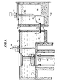
- Fig. 1 illustrates in simplified, schematic form, a typical nuclear reactor power system including a nuclear reactor vessel 10 supported within a containment structure 12.
- the walls of the containment structure are formed of reinforced concrete with suitable shielding.
- the top enclosure 11 of the reactor vessel 10 is capable of being opened through suitable remote means, to expose the interior of the reactor vessel 10 and particularly the fuel assemblies therein.
- a refueling machine 14 is mounted to travel on a suitable track 16 and includes a mast 18 which is capable of being positioned to extend into the interior of the reactor vessel 10, either to position a new fuel assembly therein or to remove a spent fuel assembly therefrom, and correspondingly to transport new fuel from, or transport spent fuel to, a fuel exchange location 20 within the containment structure 12.
- a fuel storage and handling building 22 serves both as a storage and handling facility for fresh fuel and a repository for receiving spent fuel.
- the fuel assemblies being exchanged are transported within the building 22 by a fuel handling machine 24 having a special tooling 26 for grasping the fuel assembly undergoing the exchange operation.
- the fuel assemblies, whether fresh or spent, are stored in appropriate locations within what is typically termed a fuel pit 28, schematically indicated to be included within the fuel storage and handling building 22 and separated from the exchange location 23 by a partition 29, access therebetween being afforded by a passageway 29a in the partition 29.
- a transfer tube 30 connects the containment structure 12 and the fuel storage and handling building 22, extending from a position within the fuel exchange location 20 of the containment structure 12 to a position within a fuel exchange location 23 of the fuel storage and handling building 22. Openings 31 and 32 at the ends of the transfer tube 30 are closed during reactor operation and are open during fuel exchange operations to permit passage of fuel through the transfer tube 30.
- boron-charged water is filled to a standing level, or head, of from 30 to 40 feet in both the containment structure 12 and the fuel storage and handling building 22, to control radiation levels and to protect workmen who are involved in the fuel exchange operations from exposure to such radiation.
- a transfer car is mounted on suitable tracks so as to travel the length of the refueling canal, the car thus passing through the transfer tube 30 and extending, as far as is necessary, into the fuel exchange locations 20 and 23.
- the transfer car carries a fuel container which is pivotally mounted so as to be upended to a vertical orientation while within the exchange locations 20 and 23 and then to be disposed horizontally for passage through the transfer tube 30.
- the transfer system necessarily must be interrupted at the ends of the transfer tube 30 to accommodate closure of the valves 31 and 32, as is required for normal operation of the reactor.
- a further problem in the design of such transfer systems is the desire to keep as much equipment out of the containment structure 12 as possible and, particularly, to avoid the use of drive mechanisms in both the containment structure 12 and the fuel storage and handling building 22; preferably, a transfer system should employ only a single drive mechanism, located in the fuel storage and handling building 22.
- the present invention resides in a remotely controlled transfer system for transferring an element through a transfer canal extending between at least first and second locations, wherein means at a predetermined position intermediate said first and second locations are selectively operable for blocking said transport canal to isolate said locations, comprising a segmented track supported in aligned relationship and transport means supported on said segmented track and moveable therealong for transporting an element through said transport canal, selectively from one to the other of said first and second locations, characterized by a segmented drive screw comprising first and second drive screw segments associated respectively with said first and second locations, respectively, first and second mounting means within said first and second locations, respectively, for rotatably mounting said respective first and second drive screw segments in axially aligned relationship and normally displaced from one another to define a gap at said predetermined position in said transport canal for accommodating said selectively operable blocking means, at least said first mounting means permitting linear movement of said corresponding first drive screw segment along said aligned axes, mating engagement means on respective, adjacent ends of said
- the system of the invention avoids the requirement for any power driven system within the containment structure, while not imposing any requirement for enlargement of the fuel storage and handling building to house the remote drive mechanisms. Moreover, the system accommodates the valve closure requirements relative to the transfer tube, while providing positive and precise, driven control of the transfer car.
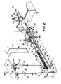
- Fig. 2 is a schematic, simplified perspective view of the remotely operable fuel transfer system of the invention, illustrating its general organization as incorporated in a conventional nuclear reactor installation of the type illustrated in Fig. 1.
- a transfer tube 30 extending between fuel exchange locations 20 and 23, respectively, within a containment structure 12 and a fuel storage and handling building 22.
- Valves 31' and 32', respectively, within the exchange locations 20 and 23 serve to close the corresponding ends 31 and 32 of the transfer tube 30 and, as schematically illustrated, are remotely operable to open positions to enable fuel transfer, or exchange, operations.
- valve 31' is illustrated to be a hatch-type valve which is mounted on a suitable bracket to permit it to be remotely operated to an open position in which it is raised vertically out of the way of the tube; similarly, valve 32' is illustrated as a gate-type valve which may be raised or lowered to open or close the corresponding end of the transfer tube 30.
- a segmented track system 40 includes segments 40a, 40b and 40c located respectively within the fuel storage and handling building 22, the transfer tube 30, and the containment structure 12.
- a transfer car 50 on which a fuel container 54 is pivotally mounted, is adapted to ride on the track system 40 to transport fuel rod assemblies between the exchange locations 20 and 23.
- An upending mechanism 90 operates to automatically pivot the container to an upended or upright position at a location in alignment with a passageway 29a which extends through the partition 29 separating the exchange location 23 from a storage and handling location or fuel pit 28 within the fuel storage and handling building 22.
- the transfer car 50 is driven by a segmented screw drive 60 having screw segments 60a, 60b and 60c fixedly mounted within the fuel storage and handling building 22, the transfer tube 30, and the containment structure 12, respectively.
- the individual segments 60a, 60b and 60c have their respective ends interlocked in mating engagement, as later detailed, so as to afford a unitary segmented drive screw 60.
- the car 50 is connected by a bracket 51 to a follower 52 received on the drive screw 60 so as to be driven laterally between the exchange locations 20 and 23 depending upon the direction of rotation of the drive screw 60.
- a remote rotary drive mechanism 70 includes a motor 71 which operates through drive gears 72 and 73 and a gear box 74 to drive a shaft 75 selectively in clockwise or counterclockwise directions. Shaft 75 in turn drives a gear box 76 which in turn drives a sliding drive gear 77, which is secured to the first drive screw segment 60a for driving same in rotation.
- a remotely controlled linear drive mechanism 80 includes a rotary power drive source 81 which, while illustrated as a simple hand wheel, may instead be a motor, for in turn driving shaft 82 which in turn actuates a linear position control mechanism 84.
- the mechanism 84 engages the first drive screw segment 60a to move same in a forward or reverse axial direction, respectively, for assembling the drive screw segments 60a, 60b and 60c to initiate a fuel exchange operation or for separating same at the conclusion of a fuel exchange operation, in a manner to be more fully described.
- specific type of linear position control mechanism 84 later detailed, it is desirable to include universal joints 83 in the shaft 82 to accommodate any offset or nonalignment condition which may exist.
- Fig. 2 also schematically illustrates an upending mechanism 90 associated with the fuel exchange location 23 within the fuel storage and handling building 22 for automatically upending the fuel assembly container 54 to its vertical position, as there illustrated, as the car 50 is driven into the exchange location 23 and reaches a position aligned with passageway 29a, as before described.
- a corresponding upending mechanism (not shown) is provided in the exchange location 20 within the fuel containment structure 12 for performing this identical function.
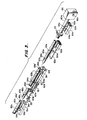
- the segmented drive screw 60 and associated supporting apparatus therefor is shown in more detail in the perspective view of Fig. 3, in which various elements are broken away and other elements, as appear in Fig. 2, are deleted to enable clarity of illustration.
- the drive screw segments 60a, 60b and 60c are mounted in somewhat similar fashion, all thereof being rotatably mounted so as to be driven in rotation; the first and second drive screw segments 60a and 60b further are mounted for linear or translational movement in a direction parallel to the common, aligned axes of all three segments.
- a segmented support channel 61 comprising segments 61a, 61b, and 61c, each of generally rectangular, hollow cross-section, the channel segments 61a and 61b respectively including open slots 62a and 62b throughout the length of their upper surfaces.
- Channel segment 61c has no requirement for the open slot but likewise is of open, or hollow, rectangular cross-section for at least a portion of its length, for a reason to be explained.
- Sliding support bars 63a and 63b of elongated form and horizontal cross-section are received within the i nterior channels of the support channel segments 61a and 61b and are free to slide therewithin.
- the first drive screw segment 60a is rotatably mounted at its first end in conventional fashion (not shown) to a drive block 66 which is secured, illustratively by a pair of pins 66a (only one of which is seen in Fig. 3), to the linear position control mechanism 84 of Fig. 2, for laterally, or axially, moving the first drive screw segment 60a, as afforded by the sliding support afforded by the associated support channel segment 61a and sliding support bar 63a.
- the channel segment 61a is fixedly secured by brackets 25 within the fuel storage and handling building 22 (Fig. 2).
- the second drive screw segment 60b is mounted within the transfer tube 30, which has been omitted in the simplified pespective view of Fig. 3 to permit clarity of illustration; the corresponding, second support channel segment 61b, however, is rigidly secured to the interior sidewall of the transfer tube 30 (see Fig. 2).
- the second drive screw segment 60b likewise is rotatably supported by rings 65b and mounted for lateral movement by corresponding vertical offsets or brackets 64b which are connected through slot 62b to the sliding support bar segment 63b within the support channel segment 61b.
- Segment 60b is biased to a normal position against stop 38, in which it is disposed toward the drive end of the screw within the transfer tube 30 with its opposite end displaced inwardly from the opposite end of the transfer tube 30.
- the biasing is accomplished by a conventional spring bias arrangement comprising a block 33 which is fixedly mounted within the tube 30, a bracket 37 secured to one of the vertical offset brackets 64b, a guide rod 34 which is carried by the bracket 37 and extends through a suitable aperture in the bracket 33, and a coil spring 35.
- a block 38 is affixed to the support channel segment 61b which acts as a stop to limit the travel of the screw segment 60b under the biasing force of the coil spring 35, and establishes the normal position of the second drive screw segment 60b within the transfer tube 30.
- the third drive screw segment 60c which is provided within the exchange location 20 of the containment structure 12, is rotatably supported by one or more rings 65c connected through corresponding vertical standoffs or brackets 64c to the support channel segment 61c which in turn is fixedly mounted within the containment structure 12. Segment 60c thus is free to rotate but is maintained in a fixed axial position.
- the drive screw segments 60a, 60b and 60c are shown in Fig. 3 in their normal, axially aligned positions, displaced with a gap therebetween so as to permit operation of the valves 31' and 32', as discussed earlier with reference to Figs. 1 and 2.
- the respectively associated, displaced ends of the first and second segments 60a and 60b, and of the second and third segments 60b and 60c are configured to have a mating relationship.
- the segments 60a and 60b respectively carry tapered pins 67a and 67b having keys 68a and 68b thereon.
- second and third segments 60b and 60c having corresponding, mating receiving bores 69b and 69c and associated keyways 69b' and 69c' for receiving the respective, tapered pins 67a and 67b and associated keys 68a and 68b.
- friction clutchs are incorporated within the rotary mounting rings 65b and 65c for the second and third segments 60b and 60c, respectively.
- the linear drive mechanism 80 (Fig. 2) is actuated to advance the drive block 66 and in turn advance the first drive screw segment 60a.
- the rotary drive mechanism 70 (Fig. 2) is operated slowly so as to rotate gear 77 and in turn the first drive screw segment 60a (Fig. 3) at a slow rate.
- the tapered pin 67a thus advances into the receiving bore 69b of the second segment 60b and the key 68a then drags on the face of the second screw segment 60b, the latter restrained from rotation by the friction clutch before noted, until key 68a is received in the corresponding keyway 69b'.
- the first segment 60b is moved continuously in the linear, or axial, direction until the two segments 60a and 60b are fully engaged, at which time continued forward motion of the drive block 66 commonly advances segments 60a and 60b thereby, in succession, to engage the mating ends of the second and third segments 60b and 60c in like manner.
- the forward ends of the sliding support bars 63a and 63b advance into the hollow channels 61b and 61c, respectively, in conjunction with the assembly of the screw drive segments 60a, 60b and 60c, and preferably are tapered to facilitate that function.
- the third segment 60c is resiliently biased to a normal axial position by a mechanism which may be similar to that employed with the second segment 60b, rather than being fixedly mounted as shown, so as to facilitate the drag function and the engagement of the key 68b in the keyway 69c'. Due to the keyway mating arrangement, the assembled segments 60a, 60b and 60c provides a continuous, albeit segmented screw drive 60 which extends from the exchange location 23 of the storage and handling building 22 to the exchange location 20 of the containment structure 12.
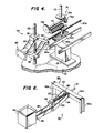
- Fig. 4 is a detailed perspective view of the gear box 76 and the linear position control mechanism 84 of Fig. 2.
- Rotary power from shaft 75 conveniently is transferred through a pair of mating bevel gears 78a and 78b and a driving gear 78c to a sliding drive joint 79 which may comprise a spline shaft or a gear on a long pinion, which in turn engages the gear 77 coupled to the drive screw segment 60a, as before described.
- the linear position control mechanism 84 as shown in Fig. 4, may have a configuration similar to a scissors jack.
- the lower end of the shaft 82 is threaded and carries thereon threaded blocks 85 which in conventional fashion are drawn closer together or spaced further apart by corresponding, opposite directions of rotation of the shaft 82, and in turn actuate the pivotally interconnected links 86 to advance or retract drive block 66, and thus the associated segmented drive screw 60, in the advancing or retracting axial directions, as before described with reference to Fig. 3.
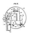
- Fig. 5 is a cross-sectional, elevational view taken along the line 5-5 in Fig. 2, for illustrating certain details of the segmented track 40 and the upending mechanism 90, both located within the fuel storage and handling building 22.
- the tracks may comprise parallel lenghths of hollow channel stock, of rectangular cross-section, one length of which is shown at 40a in Fig. 5.
- the other channel of track 40a is not illustrated in Fig. 5, to permit illustrating the aligned segment 40b, which conveniently may comprise an L-shaped right angle piece of bar stock which is secured directly to the interior of the transfer tube 30, in alignment with the channel 40a forming the right hand track (not shown) in the orientation of Fig. 5.
- a vertical beam 41a is secured to the channel stock comprising the track segment 40a illustrated in Fig. 5 and supports on its upper edge the support channel segment 61a on which the sliding support bar 63a is received.
- the vertical bracket 64a extending through slot 62a is also readily seen in Fig. 5.
- the transfer car 50 is supported on the segmented track 40 by a plurality of generally vertically oriented wheels 56 and two or more pairs of horizontally oriented wheels 56' which engage the interior, or facing, vertical surfaces of the segmented track 40 to provide lateral support, the wheels 56 and 56' of course being rotatably mounted to the frame 58.
- follower 52 is internally threaded, and may comprises a roller type nut or a screw thread type nut, so as to be engaged on the segmented drive screw 60, shown particulary for segment 60a in Fig. 5.
- the follower 52 is split to permit it to pass over the vertical standoffs, e.g., standoff 64a seen in Fig. 5, bracket 51 further including horizontal and vertical supports 55 and 57 connected to the frame 58.
- the car 50 is maintained in the storage and handling building 22, when not in use.
- drive nut 52 normally remains engaged on the first drive screw segment 60a.
- the linear drive mechanism 84 is advanced during the initial engagement of the drive screw segments 60a, 60b and 60c, the car 50 correspondingly is advanced linearly by the linear movement of segment 60a in addition to being advanced laterally by the slow rotation of the first drive segment 60a. That condition continues until all three segments 60a, 60b and 60c are interengaged. Thereafter, the rotary drive mechanism 70 may be adjusted to increase the rate of rotation of the segmented screw drive 60 to permit corresponding, more rapid lateral movement of the car 50.
- While the fuel container 54 is illustrated in a vertical position in Fig. 2, as before noted, it is automatically shifted to a horizontal position for passing through the transfer tube 30, both in travelling from the fuel exchange location 23 to the exchange location 20, and in the reverse direction of travel as well.
- This is performed by the upending mechanism 90 of Fig. 2, shown in further detail in the enlarged perspective view of Fig. 6, relevant portions thereof as well appearing in Fig. 5.
- a corresponding upending mechanism is provided in the exchange location 20 within the fuel storage and handling building 12, but is not shown since it may be substantially identical, as later detailed.
- the upending mechanism 90 includes a supporting frame 92 having vertical supports 92a and a horizontal cross bar 92b. (See Fig. 6.)
- a U-shaped bracket 94 is secured rigidly to the horizontal cross bar 92b, depending angularly downwardly therefrom, relative to the horizontal.
- Parallel, spaced L-shaped brackets 95 are pivotally mounted to the lower extremities of the side arms of the U-shaped bracket 94 and a pin 96 (Figs. 5 and 6) extends between the extremities of the longer legs of the L-shaped brackets 95 (see Fig. 5).
- a rod 97 extends through an enlarged aperture 98 in the horizontal cross bar 92b, which permits a degree of pivotally upward and downward movement of the rod 97 therein, the opposite end of rod 97 being secured within block 99 which in turn is pivotally connected to the shorter legs of the L-shaped brackets 95.
- Coil spring 100 is received over the rod 97 and maintained under compression.
- the upper sidewall of the fuel container 54 when horizontally disposed as shown in Fig. 5, includes a generally U-shaped bracket 110, having a throat which is parallel to that same upper sidewall of the fuel container 54 as above defined and which face the upending mechanism 90 as the car 50 approaches same when passing from the transfer tube 30 into the exchange location 23.
- the L-shaped brackets 95 normally are rotated, by the force of coil spring 100 acting on block 99, about the pivotal connection to the U-shaped supporting bracket 94, to position the longer legs thereof against a stop in a generally vertical orientation.
- the U-shaped bracket 110 thus engages the pin 96 as the car 50 is transported past the upending mechanism 90.
- brackets 95 As the car continues to move, the lower ends of brackets 95 are rotated upwardly, correspondingl y rotating the container 54 to an upright position and compressing the spring 100. In the reverse movement of the car 50, the compression of spring 100 acts against block 99 to rotate the L-shaped bracket 95 downwardly, permitting the container 54 as well to pivot downwardly to a horizontal position and returning the longer legs of the L-shaped brackets 95 to their normally vertical positions, in preparation for a subsequent upending operation.
- an upending mechanism for use in the containment structure 12 may be similar, as before noted, to the upending mechanism 90 employed in the exchange location 22, it will be apparent that certain reversals of parts will be necessary.
- a bracket identical to the bracket 110 is mounted on the opposite, parallel surface of the container 54 with the open throat thereof facing in the opposite direction so that it can correspondingly engage a pin such as the pin 96 of an upending mechanism which would be substantially identical to the upending mechanism 92 as shown in Fig. 6, but positioned beneath the track segment 40c in the containment structure 12. It is apparent of course that the container 54, as rotated into a vertical position as seen in Fig. 2, is open at the upper end and necessarily closed at the bottom end.
- the container moreover is rotated from a horizontal position in passing from the transfer tube 30 into the exchange location 23, in a counter clockwise direction for pivoting to the upright position as seen in Fig. 2.
- the container In the exchange location 20 of the containment structure 12, the container necessarily must rotate in that same counterclockwise direction, as viewed in Fig. 2, such that the open end is rotated to the upper position in the vertical orientation of the container 54.
- Fig. 6 therefore, if the same were rotated 180° (i.e., viewed in an upside down position) and if the open end of the container 54 as illustrated therein were instead the closed end, it will be apparent that the identical mechanism of Fig. 6 would function to achieve the appropriate direction of rotation, or pivoting, of the container 54, when employed in the exchange location 20 as described, to fulfill the required upending operation.
- the segmented and remotely connectable drive system of the invention occupies a minimum of space within the fuel storage and handling building.
Landscapes
- Physics & Mathematics (AREA)
- Engineering & Computer Science (AREA)
- Plasma & Fusion (AREA)
- General Engineering & Computer Science (AREA)
- High Energy & Nuclear Physics (AREA)
- Transmission Devices (AREA)
- Selective Calling Equipment (AREA)
- Monitoring And Testing Of Nuclear Reactors (AREA)
- Screw Conveyors (AREA)
Applications Claiming Priority (2)
| Application Number | Priority Date | Filing Date | Title |
|---|---|---|---|
| US06/785,814 US4649016A (en) | 1985-10-09 | 1985-10-09 | Remotely operable fuel transfer system for nuclear reactor |
| US785814 | 1985-10-09 |
Publications (2)
| Publication Number | Publication Date |
|---|---|
| EP0219318A2 true EP0219318A2 (de) | 1987-04-22 |
| EP0219318A3 EP0219318A3 (de) | 1988-04-27 |
Family
ID=25136706
Family Applications (1)
| Application Number | Title | Priority Date | Filing Date |
|---|---|---|---|
| EP86307825A Withdrawn EP0219318A3 (de) | 1985-10-09 | 1986-10-09 | Fernbedienbares Brennstoffschleusensystem für Kernreaktor |
Country Status (4)
| Country | Link |
|---|---|
| US (1) | US4649016A (de) |
| EP (1) | EP0219318A3 (de) |
| JP (1) | JPS6288998A (de) |
| KR (1) | KR870004461A (de) |
Cited By (1)
| Publication number | Priority date | Publication date | Assignee | Title |
|---|---|---|---|---|
| FR2700881A1 (fr) * | 1993-01-28 | 1994-07-29 | Framatome Sa | Voie de roulement pour chariot destiné à transporter sous eau des assemblages de combustible nucléaire. |
Families Citing this family (23)
| Publication number | Priority date | Publication date | Assignee | Title |
|---|---|---|---|---|
| US4761107A (en) * | 1986-06-19 | 1988-08-02 | Westinghouse Electric Corp. | Apparatus for transferring components to and from containers |
| US4749541A (en) * | 1986-12-05 | 1988-06-07 | Westinghouse Electric Corp. | Position sensing mechanism for a nuclear fuel transfer system |
| US4725398A (en) * | 1986-12-08 | 1988-02-16 | Nuclear Energy Services, Inc. | Cable reeving system |
| US5195391A (en) * | 1988-10-31 | 1993-03-23 | Deutsche Star Gmbh | Linear guiding and driving unit |
| DE8910548U1 (de) * | 1988-10-31 | 1989-11-02 | Deutsche Star Gmbh, 8720 Schweinfurt | Linearführungs- und Antriebseinheit |
| JPH0694896B2 (ja) * | 1988-11-16 | 1994-11-24 | テイエチケー株式会社 | ボールねじ |
| US5085094A (en) * | 1990-11-08 | 1992-02-04 | Gmi Holdings, Inc. | Door operator coupling assembly |
| US5588257A (en) * | 1994-08-24 | 1996-12-31 | The Stanley Works | Garage door operator |
| DE29720447U1 (de) * | 1997-11-18 | 1998-04-02 | MARANTEC Antriebs- und Steuerungstechnik GmbH & Co. Produktions-KG, 33428 Marienfeld | Antriebsspindel |
| US6885718B1 (en) * | 1998-03-19 | 2005-04-26 | Framatome Anp Gmbh | Method and apparatus for transferring an article between fluid-filled vessels |
| US6404836B1 (en) * | 1999-02-12 | 2002-06-11 | Westinghouse Electric Company Llc | Removable spent fuel handling machine rail |
| US6474923B1 (en) * | 2000-02-22 | 2002-11-05 | The United States Of America As Represented By The United States Department Of Energy | Sample push-out fixture |
| JP2005195159A (ja) * | 2004-01-09 | 2005-07-21 | Nsk Ltd | ボールねじ装置 |
| EP2027585B1 (de) * | 2006-05-23 | 2016-01-27 | MHE Technologies, Inc. | Brennstofftransfersystem |
| US8811561B2 (en) * | 2009-06-10 | 2014-08-19 | Babcock & Wilcox Nuclear Operations Group, Inc. | Control rod drive mechanism for nuclear reactor |
| FR2964781B1 (fr) * | 2010-09-15 | 2012-10-19 | Areva Np | Dispositif de manutention a sec d'assemblages de combustible nucleaire |
| FR2971881A1 (fr) * | 2011-02-18 | 2012-08-24 | Areva Np | Dispositif de retournement d'un conteneur, notamment pour assemblage de combustible nucleaire, ensemble de retournement et centrale nucleaire |
| DE102012207473A1 (de) * | 2012-05-04 | 2013-11-07 | Areva Gmbh | Brennelementlagerbecken eines Kernkraftwerks |
| CN103219056B (zh) * | 2013-03-29 | 2015-12-02 | 中国核电工程有限公司 | 燃料转运装置及其运输小车接力驱动的控制系统及方法 |
| CN110148482B (zh) * | 2019-05-31 | 2024-03-26 | 中核能源科技有限公司 | 一种自动扶梯式燃料传输装置 |
| WO2021248387A1 (zh) * | 2020-06-10 | 2021-12-16 | 中广核研究院有限公司 | 一种换料转运设备及换料方法 |
| CN113284641A (zh) * | 2021-04-29 | 2021-08-20 | 中国核电工程有限公司 | 一种可实现长行程运行的燃料转运装置 |
| CN115831411B (zh) * | 2022-12-28 | 2024-05-31 | 中国原子能科学研究院 | 乏燃料组件抓取装置 |
Family Cites Families (14)
| Publication number | Priority date | Publication date | Assignee | Title |
|---|---|---|---|---|
| US3955692A (en) * | 1954-06-03 | 1976-05-11 | The United States Of America As Represented By The United States Energy Research And Development Administration | Handling apparatus |
| BE555442A (de) * | 1956-03-01 | |||
| US2893769A (en) * | 1956-07-20 | 1959-07-07 | Deliso John | Socket and rod coupling |
| GB1018948A (de) * | 1962-02-20 | |||
| US3485520A (en) * | 1968-05-01 | 1969-12-23 | Rayburn G Alexander | Self-locking connection between rigid members and method of making same |
| FR2240340B1 (de) * | 1973-07-27 | 1976-09-17 | Faiveley Sa | |
| FR2259286A1 (en) * | 1974-03-29 | 1975-08-22 | Machou Albert | Drive transmission coupling for shafts - has sleeve keyed to one shaft splined into end of second shaft |
| US3940577A (en) * | 1974-06-12 | 1976-02-24 | Stock Equipment Company | Method and apparatus for controlling a transfer car from a remote station |
| US4241540A (en) * | 1979-07-18 | 1980-12-30 | Chamberlain Manufacturing Corporation | Folding screw and rail assembly for a garage door opener |
| DE7923201U1 (de) * | 1979-08-14 | 1979-11-08 | Kunz Masch App | Vorrichtung zum kuppeln eines wickelstabes o.dgl. mit einer mitnehmerwelle |
| US4352585A (en) * | 1980-03-06 | 1982-10-05 | The Alliance Manufacturing Company, Inc. | Door operator screw coupling |
| FR2520150A1 (fr) * | 1982-01-20 | 1983-07-22 | Alsthom Atlantique | Dispositif pour transferer horizontalement entre deux enceintes des elements combustibles nucleaires stockes en position verticale |
| DE3304002C1 (de) * | 1983-02-02 | 1984-07-19 | Mannesmann AG, 4000 Düsseldorf | Vorschubeinrichtung eines Kaltpilgerwalzwerks |
| US4717531A (en) * | 1983-09-23 | 1988-01-05 | Westinghouse Electric Corp. | Fuel transfer system upender using translation drive |
-
1985
- 1985-10-09 US US06/785,814 patent/US4649016A/en not_active Expired - Fee Related
-
1986
- 1986-10-08 KR KR1019860008465A patent/KR870004461A/ko not_active Withdrawn
- 1986-10-09 JP JP61241194A patent/JPS6288998A/ja active Pending
- 1986-10-09 EP EP86307825A patent/EP0219318A3/de not_active Withdrawn
Cited By (1)
| Publication number | Priority date | Publication date | Assignee | Title |
|---|---|---|---|---|
| FR2700881A1 (fr) * | 1993-01-28 | 1994-07-29 | Framatome Sa | Voie de roulement pour chariot destiné à transporter sous eau des assemblages de combustible nucléaire. |
Also Published As
| Publication number | Publication date |
|---|---|
| EP0219318A3 (de) | 1988-04-27 |
| KR870004461A (ko) | 1987-05-09 |
| US4649016A (en) | 1987-03-10 |
| JPS6288998A (ja) | 1987-04-23 |
Similar Documents
| Publication | Publication Date | Title |
|---|---|---|
| EP0219318A2 (de) | Fernbedienbares Brennstoffschleusensystem für Kernreaktor | |
| DE3852836T2 (de) | Automatisches Bandkassettenaustauschsystem. | |
| US4317021A (en) | Laser cutting apparatus for nuclear core fuel subassembly | |
| US3691011A (en) | Loading device for fuel elements and control rods in a nuclear reactor | |
| EP0556022A1 (de) | Brennstabbündelüberführungssystem | |
| US4706905A (en) | Reel stand | |
| JPS62174494A (ja) | 掘削装置 | |
| DE4104566C2 (de) | Fernsteuerbare Wartungsvorrichtung für gefäßinnere Bauteile bei einer Konstruktion mit einem inneren Torus- oder Ringraum | |
| DE4431881A1 (de) | Vorrichtung und Verfahren zum Positionieren von lichtempfindlichen Medien auf einer Belichtungsplatte | |
| US5385102A (en) | Vehicle for the automatic laying of a track by a vehicle travelling on said track and track designed for installation by such a vehicle | |
| US3383286A (en) | Core element handling system | |
| US4425298A (en) | Baffle maintenance apparatus | |
| US4231696A (en) | Multi-function end effector | |
| US4207723A (en) | Canning and inspection system for nuclear reactor fuel and reflector elements | |
| US4421715A (en) | Baffle maintenance apparatus | |
| US3483380A (en) | Shielded cask for radioactive material | |
| DE10206837A1 (de) | Fördersystem | |
| US3672247A (en) | Apparatus and method for processing spent nuclear fuel elements | |
| US4095495A (en) | Method and device for cutting a bundle of irradiated nuclear fuel tubes | |
| US6773219B2 (en) | Control rod drive handling assembly for a nuclear reactor | |
| DE2746391A1 (de) | Lade/entlade-vorrichtung fuer brennelementbuendel fuer kernreaktoren | |
| US5305358A (en) | Control rod drive handling equipment | |
| US4728484A (en) | Apparatus for handling control rod drive | |
| DE3248592C2 (de) | ||
| US4705661A (en) | Fast neutron nuclear reactor equipped with a central handling cell and a boxed slab |
Legal Events
| Date | Code | Title | Description |
|---|---|---|---|
| PUAI | Public reference made under article 153(3) epc to a published international application that has entered the european phase |
Free format text: ORIGINAL CODE: 0009012 |
|
| AK | Designated contracting states |
Kind code of ref document: A2 Designated state(s): BE CH ES FR GB IT LI NL |
|
| PUAL | Search report despatched |
Free format text: ORIGINAL CODE: 0009013 |
|
| AK | Designated contracting states |
Kind code of ref document: A3 Designated state(s): BE CH ES FR GB IT LI NL |
|
| STAA | Information on the status of an ep patent application or granted ep patent |
Free format text: STATUS: THE APPLICATION IS DEEMED TO BE WITHDRAWN |
|
| 18D | Application deemed to be withdrawn |
Effective date: 19890501 |
|
| RIN1 | Information on inventor provided before grant (corrected) |
Inventor name: HARDIN, ROY TYLER, JR. |