EP0219096A2 - Faseroptischer Sternkoppler und seine Herstellungsmethode - Google Patents
Faseroptischer Sternkoppler und seine Herstellungsmethode Download PDFInfo
- Publication number
- EP0219096A2 EP0219096A2 EP86114218A EP86114218A EP0219096A2 EP 0219096 A2 EP0219096 A2 EP 0219096A2 EP 86114218 A EP86114218 A EP 86114218A EP 86114218 A EP86114218 A EP 86114218A EP 0219096 A2 EP0219096 A2 EP 0219096A2
- Authority
- EP
- European Patent Office
- Prior art keywords
- optical fiber
- star coupler
- plastic optical
- manufacturing
- bundle
- Prior art date
- Legal status (The legal status is an assumption and is not a legal conclusion. Google has not performed a legal analysis and makes no representation as to the accuracy of the status listed.)
- Withdrawn
Links
Images


Classifications
-
- B—PERFORMING OPERATIONS; TRANSPORTING
- B29—WORKING OF PLASTICS; WORKING OF SUBSTANCES IN A PLASTIC STATE IN GENERAL
- B29D—PRODUCING PARTICULAR ARTICLES FROM PLASTICS OR FROM SUBSTANCES IN A PLASTIC STATE
- B29D11/00—Producing optical elements, e.g. lenses or prisms
- B29D11/00663—Production of light guides
-
- G—PHYSICS
- G02—OPTICS
- G02B—OPTICAL ELEMENTS, SYSTEMS OR APPARATUS
- G02B6/00—Light guides; Structural details of arrangements comprising light guides and other optical elements, e.g. couplings
- G02B6/24—Coupling light guides
- G02B6/26—Optical coupling means
- G02B6/28—Optical coupling means having data bus means, i.e. plural waveguides interconnected and providing an inherently bidirectional system by mixing and splitting signals
- G02B6/2804—Optical coupling means having data bus means, i.e. plural waveguides interconnected and providing an inherently bidirectional system by mixing and splitting signals forming multipart couplers without wavelength selective elements, e.g. "T" couplers, star couplers
- G02B6/2856—Optical coupling means having data bus means, i.e. plural waveguides interconnected and providing an inherently bidirectional system by mixing and splitting signals forming multipart couplers without wavelength selective elements, e.g. "T" couplers, star couplers formed or shaped by thermal heating means, e.g. splitting, branching and/or combining elements
Definitions
- the present invention relates to an optical fiber star coupler by which a light beam transmitted through an optical fiber is divided to a plurality of optical fibers, and a method of manufacturing the optical fiber star coupler. It is well suited to form a star coupler by the use of plastic optical fibers.
- optical data links which use optical fibers for the data transmission between electronic computers and between an electronic computer and a terminal.
- the optical star coupler which can mix optical signals from a plurality of input optical fibers and then divide them to a plurality of output optical fibers with low loss and equally is an indispensable device.
- a typical example of the optical star coupler has been a biconically tapered type shown in Fig. 4.
- Such biconically tapered type optical star coupler is shown, for instance, in i) "Optical Communication Handbook" edited by Hisayoshi Yanai and issued by Asakura-Shoten on September 1, 1982, pages 324 and 325, ii) T. Ozeki et al.: Electronics Letters, Vol. 12, No. 6 (1976), pages 151 and 152, and iii) E. G. Rawson et al.: Electronics Letters, Vol. 14, No. 9 (1978), pages 274 and 275. Accordingly, it is well known.
- a multiplicity of optical fibers 1 are bundled together, and the middle part of the bundle is pulled under twisting while being heated by a heating source, to form a biconically tapered region 2, whereby optical signals from the input optical fibers (the left side of the tapered region 2) are divided to a plurality of output optical fibers (the right side of the tapered region 2).
- plastic optical fibers have a low melting point (about 100 °C) and react very sensitively to temperatures, they are liable to unnecessary deformations or breakage attributed to fusion, to incur the problem of thermal workability.
- the plastic optical fiber has a large diameter (usually, an outside diameter of 0.5 - 1.0 mm) as shown in Figs. 13A and 13B, and the refractive index difference between a core 3 and n 1 - n 2 a cladding 4,
- the degree of power concentration P in the core is expressed by: where
- An object of the present invention is to provide a biconically tapered type optical star coupler of low loss and low power deviation characteristics which is made of plastic optical fibers.
- the object is accomplished in such a way that the outer peripheral surface of a biconically tapered portion is quenched by blowing a gas against it when a desired shape has been realized in case of forming and working a plastic optical fiber bundle into the biconically tapered shape.
- the object is accomplished by manufacturing an optical fiber type star coupler of biconically tapered shape in such a way that plastic optical fibers are bundled after coating the outer peripheral surfaces of the optical fibers with a solvent for dissolving the optical fibers, or that an optical fiber bundle is previously coated with the solvent, and that the optical fiber bundle is thereafter heated, whereupon it is pulled while being twisted in accordance with the softening thereof.
- the object is accomplished in such a way that individual optical fibers are pulled beforehand, that these pulled optical fibers are bundled, and that the pulled part is twisted, fused and pulled while being heated, into an optical star coupler.
- a plastic fiber bundle is first heated by a heating source (for example, electric heater) up to a temperature at which fibers soften.
- a heating source for example, electric heater
- the fiber bundle is pulled in axial opposite directions while being twisted.
- the twisting and the pulling are performed until the output optical powers of the individual fibers on the output side of the fiber bundle are equally divided by putting light into any one of the fibers on the input side.
- the middle part of the fiber bundle decreases in the cross-sectional area thereof.
- the first embodiment of the present invention consists in a method in which, the moment the equally dividing characteristic has been substantially realized, a gas is forcibly blown against the outer peripheral surface of the biconically tapered portion, thereby quenching the biconically tapered portion so as to check the promotion of the softening thereof. As a result, the fusing is not involved, and a low power deviation characteristic is maintained.
- the biconically tapered portion undergoes a compression stress owing to the quenching, the mechanical strength thereof rises.
- the blowing of the gas is not attended with any unnecessary deformation and can suppress the adhesion and mixing of impurities (for example, dust and moisture in the air, alkaline metal ions, alkaline-earth metal ions and transition metal ions) on and into the biconically tapered portion, so that a low loss characteristic is attained.
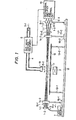
- Fig. 1 shows a schematic view of the first embodiment of a method of manufacturing a plastic optical fiber star coupler according to the present invention.
- This embodiment is the manufacturing method for a 3 x 3 fiber type optical star coupler in which both the. numbers of input port fibers and output port fibers are three.
- plastic fibers 1-1, 1-2 and 1-3 has a core made of polystyrene (refractive index: 1.59) and a cladding made of polymethyl methacrylate (refractive index: 1.49).
- the outside diameter of the cladding is 0.7 mm.
- the three fibers are fixed to fixing portions 14-1 and 14-2, and the light of a light source 7 (in this case, a He-Ne laser source was used) is caused to enter the input port side of the fiber 1-3.
- the fixing portions 14-1 and 14-2 include mechanism portions which are rotated in the directions of arrows 15-1 and 15-2, respectively.
- Shown at numeral 3 is a heating source, as which a hydrogen burner capable of raising and lowering temperatures more conveniently was used. Otherwise, an electric heater, a hot air drier, an RF induction heater or the like may be used.
- Numeral 12 designates a glass plate, which is a protective plate that serves to prevent the flames and wind pressure of the hydrogen burner from directly acting on the fiber bundle and incurring any unnecessary deformation and which brings forth an indirect heating effect.
- Symbols 13-1 and 13-2 denote pedestals for supporting the glass flat plate 12.
- Moving portions 16-1 and 16-2 are furnished with mechanisms capable of moving in the directions of arrows 17-1 and 17-2 on a base 18, respectively.
- Optical detectors 9-1 to 9-3 are constructed in the shape of an array, and they convert into electric signals the output lights of the respective output port fibers 1-1, 1-2 and 1-3.
- Numeral 10 indicates an operational amplifier and control circuit, which is so set as to generate a voltage signal for driving a gas valve control equipment 6 when the output signals of the respective optical detectors 9-1, 9-2 and 9-3 have become substantially equal.
- a circuit can be readily realized using conventional arithmetic circuits, amplifier circuit etc.
- the gas valve control equipment 6 which is normally closed is opened by the signal of the operational amplifier and control circuit 10, and a gas fed in the direction of an arrow 5-1 is caused to flow in the directions of arrows 5-2.
- Shown at numeral 19 is a gas blast nozzle.
- the heating source 3 constructed of the hydrogen burner is ignited to indirectly heat the plastic fiber bundle (1-1, 1-2, 1-3).
- the flow rate of H 2 gas is at most 1 lit./min.
- the rotating mechanism portions of the fixing portions 14-1 and 14-2 are driven to rotate (3 - 10 revolutions) in the directions of the arrows 15-1 and 15-2 respectively, whereby the softened optical fiber bundle is twisted.
- the moving portions 16-1 and 16-2 are driven to move in the directions of the arrows 17-1 and 17-2 respectively. The movements are performed until the output signals of the respective optical detectors become equal.
- the valve control equipment 6 operates, and the gas (the air was used in this case, but a gas such as 0 2 , N 2 , Ar or He may well be employed) coming in the direction of the arrow 5-1 is caused to flow in the directions of the arrows 5-2, thereby to quench a twisting, fusing and pulling portion 11 (biconically tapered portion).
- the hydrogen burner 3 is turned off to be put out automatically or manually at the stage at which the output signals of the optical detectors have equalized.
- the optical star coupler prepared by such a method exhibited an excess loss of 0.83 dB and a power deviation of ⁇ 0.6 dB.
- a 15 x 15 fiber type optical star coupler was similarly prepared, and the results of an excess loss of 2.54 dB and a power deviation of ⁇ 1.35 dB were obtained.
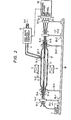
- Fig. 2 shows the second embodiment of the method of manufacturing a plastic optical fiber star coupler according to the present invention.
- This corresponds to a case where the glass flat plate 12 in Fig. 1 is replaced with a glass tube (a quartz glass tube, a pyrex glass tube or the like) 21.
- the glass tube 21 is provided with a hole 20-1.
- the gas is caused to flow into the glass tube 21 through the hole 20-1 as indicated by an arrow 5-2, and is caused to flow out as indicated by arrows 5-3, 5-4 and 5-5.
- the gas may well be caused to flow in also through a hole 20-2.
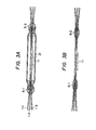
- Figs. 3A and 3B show schematic views of plastic optical fiber star couplers produced by the embodiments.
- Shown in Fig. 3A is a structure in which the biconically tapered portion 11 is inserted within the glass tube 21, and both the ends of the tube are sealed by binder deposits 8-1 and 8-2. It has been manufactured by the method of the embodiment in Fig. 2.
- Shown in Fig. 3B is a structure in which, after the preparation by the method of the embodiment in Fig. 1, the vicinities of the left and right ends of the biconically tapered portion 11 are respectively fixed by binder deposits 8-1 and 8-2.
- the biconically tapered portion 11 may well be covered with a transparent material which has a refractive index lower than that of the cladding of the fiber.
- an optical star coupler which is excellent in reliability can be formed.
- the numbers of input and output ports may be two or more.
- Usable as the material of the plastic fibers is any of various materials such as Teflon (trade name of Du Pont Inc.), polychlorostyrene, polytrifluoroisopropyl methacrylate, polycarbonate, and diethyleneglycol bisarylcarbonate.
- a burner of any combustible gas not containing oxygen or the like oxidizing gas, such as town gas or propane gas, may be employed otherwise than the hydrogen burner.
- the quenching effect can also be expected in such a way that the quenching gas to flow in the directions of the arrows 5-1 and 5-2 is normally kept flowing during the twisting, fusing and pulling of the optical fiber bundle and that the hydrogen burner 3 is turned off at the stage at which the equally dividing characteristic has been achieved.
- the flow rate of the gas need to be suitable for sufficiently cooling the surface of the optical fiber bundle and may be set at or above 2 lit./min.
- the flow rate of the gas normally kept flowing may well be increased the moment the hydrogen burner 3 has been turned off.
- the embodiments bring forth the effect that a plastic optical fiber star coupler having low loss and low power deviation characteristics can be readily fabricated as the biconically tapered type.
- Figs. 5A and 5B show the third embodiment of the present invention in which a solvent is applied to the outer peripheral surface of a plastic optical fiber.
- Numeral 103 designates a plastic optical fiber, the core of which is made of polystyrene (refractive index: 1.54) and the cladding of which is made of polymethyl methacrylate (refractive index: 1.49).
- Numeral 104 indicates a vessel for containing a solvent 105. A cellosolve system or ketone system is appropriate for the solvent 105, and methyl isobutyl ketone or methyl ethyl ketone is mentioned by way of example. In this embodiment, methyl isobutyl ketone was used.
- the dissolution degree of the outer peripheral surface of the plastic fiber can be controlled by the period of time for which the plastic fiber is immersed in the solvent 105.
- Fig. 5B shows the plastic fiber with the solvent 105 deposited thereon, and a part 106 is a solvent-deposited portion.
- the period of time of the immersion of the plastic fiber in the solvent 105 was variously changed between 30 seconds and 10 minutes. In a case where the immersion period of time was long, the surface of the fiber became rugged to be devitrified. This is attributed to the fact that the dissolution proceeded excessively.
- the appearance of the ruggedness can be prevented by mixing an alcoholic liquid (for example, isopropyl alcohol or methanol) into the solvent 105 as a dissolution depressor. In this case, the mixing ratio between the solvent and the dissolution depressor is selected from within a range from 1-to-1 to 1-to-3 or so.
- the dissolution rate can also be controlled by the temperature of the solvent.
- Fig. 6 shows the third embodiment of the method of manufacturing a plastic optical fiber star coupler according to the present invention.
- the plastic fibers 103-1 and 103-2 obtained by the method illustrated in Figs. 5A and 5B are arrayed in parallel in close contact, and the vicinities of the parts with the solvent deposited thereon are heated by a heating source 107 (in this case, an electric heater was used).
- a heating source 107 in this case, an electric heater was used.
- the heating is conducted in an oxidizing atmosphere, the fiber surface sometimes reacts with oxygen to develop a coloring phenomenon, and hence, the heating should preferably be conducted in an inactive gas atmosphere.
- Suitable for the inactive gas atmosphere is N 2 , Ar, He or the like or a gaseous mixture consisting of them.
- the fiber bundle is pulled in the directions of arrows 108 and 109 while being rotated in the directions of arrows 110 and 111 and being thus twisted in accordance with the softening of the fibers owing to the heating, whereby a biconically tapered shape is formed in a region 112.
- a fiber bundle without the deposition of the solvent was similarly heated, twisted and pulled to prepare a biconically tapered shape, and the transmission characteristics of the prior art and the present invention were compared.
- the branching ratio was 1-to-1 and the excess loss was 1.2 dB
- the branching ratio was 1.4-to-0.6 and the excess loss was 2.3 dB.
- the two fibers were not completely fused together, and they were separated when drawn coercively. In contrast, in the case of this embodiment, the two fibers were completely fused together.
- the fiber surface will be polluted with impurities etc. and will therefore be difficult to melt.
- the solvent deposition will have a surface etching effect, and moreover, the dissolution of the surfaces will hold the fibers easy to be bonded to each other.
- the fiber bundle may well be twisted before being heated.
- Fig. 7 shows an embodiment of the plastic optical fiber star coupler of the present invention. It corresponds to a case where the numbers of input and output port fibers 115-1 and 115-2 are four respectively.
- Numeral 113 designates a biconically tapered portion, and numeral 114 a cover material of high polymer for protecting the biconically tapered portion 113.
- the cover material 114 may be a material the refractive index of which is equal to or lower than that of the cladding material of the fiber.
- the biconically tapered portion is similarly covered with polymethyl methacrylate or is covered with a fluoro-polymer (for example, polyvinylidene fluoride or the copolymer between vinylidene fluoride and tetrafluoroethylene).
- a fluoro-polymer for example, polyvinylidene fluoride or the copolymer between vinylidene fluoride and tetrafluoroethylene.
- the present invention is not restricted to the above embodiments.
- it is effective to couple the fibers more closely and to reduce the excess loss that, in Fig. 5A, the solvent 105 contains therein a dopant which diffuses from the outer peripheral surface of the cladding of the optical fiber into the cladding to raise the refractive index of this cladding.
- a dopant which diffuses from the outer peripheral surface of the cladding of the optical fiber into the cladding to raise the refractive index of this cladding.
- x weight-parts of styrene monomer and y weight-parts of methyl methacrylate monomer are mixed into the solvent.
- the refractive index can be controlled by changing the ratio between the values x and y.
- This embodiment is applicable to plastic fibers of various core materials and cladding materials.
- the materials are, for example, polycarbonate, polychlorostyrene, polytrifluoroisopropyl methacrylate, diethyleneglycol bisarylcarbonate, and Teflon (trade name of Du Pont Inc.).
- dimethylformamide was used as the solvent for a core material of polymethyl methacrylate and a cladding material of polyvinylidene fluoride.
- fibers were favorably fused to togetherer, and the branching ratio and the excess loss were favorable characteristics as stated before.
- a plastic optical fiber star coupler of novel structure having excellent branching ratio and excess loss characteristics can be obtained with ease. Moreover, even when the star coupler is used over a long term, degradation is difficult to occur because a biconically tapered portion is completely fused integrally.
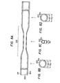
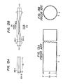
- a plastic optical fiber 201 is pulled as shown in Fig. 8A beforehand, to form a biconically tapered shape and to waist the middle part 205 thereof.
- Figs. 8B to 8D show the sections of the parts of the plastic optical fiber in Fig. 8A respectively indicated by arrows.
- numeral 203 denotes a core
- numeral 204 a cladding.
- the rate K of the conversion from the core mode into c the cladding mode is expressed by: where a O : diameter of the core of the fiber before the pulling, a 1 : diameter of the core of the middle part 205 after the pulling.
- This value K c is equal to the decreasing rate K p of propagating mode numbers (N 0 , N 1 ) before and after the pulling. That is, where
- the individual fibers have been uniformly pulled, the divisions of light in the tapered portions of the input side become uniform, and the conversion rates from the cladding mode into the core mode become uniform in the tapered portions of the output side, so that the power deviation can be suppressed to a very small value.
- the cladding is uniformly thinned by the pulling, the excess loss can be reduced more.
- radiation in the tapered portion takes place. Letting r denote the diameter of the fiber at which the radiation occurs, a non-radiation condition will be found.
- a light beam having entered the tapered portion propagates while being reflected by the interfaces between the core and the air. Each time the light beam is reflected, the angle of reflection increases (Fig. 9).
- the non-radiation condition in the state of Fig. 9 is: where
- the second feature of the present embodiment consists in that the fibers pulled in advance are bundled, and that the waisted portion of the middle parts of the bundled fibers is twisted while being heated or is slightly pulled while being twisted. That is, only the waisted middle portion is twisted and is slightly pulled, and the resulting portion is used as a so-called mixing portion.
- the mixing portion about 20 % of the core mode not converted into the cladding mode is entirely converted into the cladding mode, whereby the whole mode is mixed and divided.
- the waist portion is processed, the temperatures of the outer peripheral part and central part of the bundle are substantially equal, and besides, the pulling length is small, so that the respective fibers are uniformly pulled.
- the waist portion is processed, the ruggedness of the outer peripheral part subjected to the twisting is slight, and scattering and radiation loss in this part are slight. Further, since the tapered portions of the input and output parts of the optical star coupler finished up include almost no twisted parts, unnecessary scattering and radiation loss are slight.
- Figs. 11A to 11E show schematic views of all the steps of the method of manufacturing the plastic optical fiber star coupler in the fourth embodiment of the present invention and the structure of the optical star coupler obtained by the method.
- These exemplify a 2 x 2 port type optical star coupler in which two plastic fibers 201-1 and 201-2 to form two input ports and two output ports, and the method of manufacturing it.
- Fig. 11A two fibers are arranged in parallel, and while the middle parts of the parallel fibers are being heated by a heating source 210, the fibers are pulled in the directions of arrows 211-1 and 211-2, to be formed into a structure as shown in Fig. 11B.
- the shape and dimensions of the pulled portion 205 are made as illustrated in Figs.
- the parallel fibers are rotated in the directions of arrows 217-1 and 217-2 so as to apply twisting 212 to the pulled portion 205.
- the number of times of the twisting is set small when the pulling ratio is large, whereas it is set large when the pulling ratio is small.
- the number of times of the twisting may be 2 - 15 or so.
- the parallel fibers are pulled in the directions of arrows 213-1 and 213-2 again while the twisted portion 212 is being heated by the heating source 210. The pulling in this case is performed so as to attain an equally dividing characteristic.
- the twisted, fused and pulled portion 214 is covered with a protective tube 215, and the protective tube 215 and the fibers are fixed by a binder 216, whereby the plastic optical fiber star coupler can be obtained.
- the protective tube 215 serves to protect the portion 214 against fluctuations in the excess loss and the power deviation characteristic, and it may be a dielectric substance tube (for example, a glass tube or plastic tube), a magnetic substance tube (for example, a ceramic tube), a conductor tube (for example, a metal tube) or the like.
- the present invention is not restricted to the above embodiment.
- the steps of Fig. 11C and Fig. 11D may well be performed simultaneously.
- the fibers may well be twisted, fused and pulled while being heated.
- the number of plastic fibers is not limited to two, but it may well be three to one hundred or so.
- the fourth embodiment is also effective in case of employing glass fibers otherwise than the plastic fibers.
- the index difference between a core and a cladding is as small as about 1 %, so that the pulling ratio in the case of the previous pulling need not be set large.
- both the low excess loss and the equally dividing characteristic can be met in an optical star coupler which employs optical fibers of large diameter and high NA.
- the optical star coupler can be manufactured at low cost by a through process.
- Figs. 12A and 12B show a plastic optical fiber coupler which was fabricated without conforming to the present invention for the purpose of a comparison experiment.
- the middle parts of two plastic optical fibers 301-1 and 301-2 were not pulled in advance.
- the plastic fibers 301-1 and 301-2 had the middle parts twisted and pulled in the axial directions thereof while the middle parts were being heated by a heating source 210, whereby a biconically tapered portion 302 was formed.
- the core mode needed to be converted into the cladding mode at a stretch by increasing the number of times of twisting and shortening the pitch of the twisting in the extreme as compared with those in the case of resorting to the present invention.
- the number of times of the twisting was increased and the twisting pitch was shortened in this manner, the radiation mode augmented, and the radiation loss became heavy, with the result that an excess loss of 5 dB arose.
Applications Claiming Priority (6)
| Application Number | Priority Date | Filing Date | Title |
|---|---|---|---|
| JP22868585A JPS6289009A (ja) | 1985-10-16 | 1985-10-16 | 光フアイバ型スタ−カプラ |
| JP228685/85 | 1985-10-16 | ||
| JP2192086A JPS62180309A (ja) | 1986-02-05 | 1986-02-05 | プラスチツクフアイバ型光スタ−カプラの製造方法 |
| JP21920/86 | 1986-02-05 | ||
| JP52437/86 | 1986-03-12 | ||
| JP5243786A JPS62210409A (ja) | 1986-03-12 | 1986-03-12 | プラスチツクフアイバ型光スタ−カプラおよびその製造方法 |
Publications (2)
| Publication Number | Publication Date |
|---|---|
| EP0219096A2 true EP0219096A2 (de) | 1987-04-22 |
| EP0219096A3 EP0219096A3 (de) | 1989-08-16 |
Family
ID=27283626
Family Applications (1)
| Application Number | Title | Priority Date | Filing Date |
|---|---|---|---|
| EP86114218A Withdrawn EP0219096A3 (de) | 1985-10-16 | 1986-10-14 | Faseroptischer Sternkoppler und seine Herstellungsmethode |
Country Status (2)
| Country | Link |
|---|---|
| US (1) | US4822128A (de) |
| EP (1) | EP0219096A3 (de) |
Cited By (10)
| Publication number | Priority date | Publication date | Assignee | Title |
|---|---|---|---|---|
| GB2199423A (en) * | 1986-12-05 | 1988-07-06 | Conleth Denis Hussey | Fibre optic transfer devices |
| EP0315874A2 (de) * | 1987-11-07 | 1989-05-17 | Hoechst Aktiengesellschaft | Verfahren zur Herstellung eines optischen Kopplers für Polymer-Lichtwellenleiter |
| GB2217473A (en) * | 1988-04-14 | 1989-10-25 | Bicc Plc | Fused optical fibre coupler manufacture |
| EP0357429A2 (de) * | 1988-09-01 | 1990-03-07 | Minnesota Mining And Manufacturing Company | Polarisationserhaltende optische Faser zur Herstellung von Kopplern |
| EP0363853A1 (de) * | 1988-10-08 | 1990-04-18 | KABEL RHEYDT Aktiengesellschaft | Verfahren zur Herstellung eines faseroptischen Sternkopplers und nach diesem Verfahren hergestellter faseroptischer Sternkoppler |
| WO1990008030A1 (en) * | 1989-01-12 | 1990-07-26 | Codenoll Technology Corporation | Injection molded star-couplers and methods of making same |
| GB2207255B (en) * | 1987-07-18 | 1991-03-20 | Stc Plc | Removing optical fibre encapsulation with a heated gas jet |
| US5019301A (en) * | 1989-01-12 | 1991-05-28 | Codenoll Technology Corporation | Method of injection molding star-couplers |
| US5035480A (en) * | 1989-09-06 | 1991-07-30 | Codenoll Technology Corporation | Star-couplers with biconical mixing elements and methods for making the same |
| EP0682275A1 (de) * | 1994-05-09 | 1995-11-15 | SIRTI S.p.A. | Methode zur Herstellung eines monolithischen Schmelzkopplers aus Einmoden-Fasern |
Families Citing this family (26)
| Publication number | Priority date | Publication date | Assignee | Title |
|---|---|---|---|---|
| US4923268A (en) * | 1987-09-14 | 1990-05-08 | Aster Corporation | Fiber optic coupler |
| US4997247A (en) * | 1987-09-17 | 1991-03-05 | Aster Corporation | Fiber optic coupler and method for making same |
| CA1308937C (en) * | 1988-01-11 | 1992-10-20 | Francois Bilodeau | Fabrication technique for low-loss fused taper directional couplers and pressure sensor produced thereby |
| JPH087295B2 (ja) * | 1988-07-13 | 1996-01-29 | 住友電気工業株式会社 | 光分岐結合器の製造方法 |
| US5058979A (en) * | 1989-06-22 | 1991-10-22 | Fujikura Ltd. | Optical fiber coupler and a fabrication method for the same |
| DE3926313A1 (de) * | 1989-08-09 | 1991-02-14 | Messerschmitt Boelkow Blohm | Faserkreisel vom sagnac-typ |
| DE3926312A1 (de) * | 1989-08-09 | 1991-02-14 | Messerschmitt Boelkow Blohm | Faserkreisel vom sagnac-typ |
| US5022735A (en) * | 1989-11-07 | 1991-06-11 | The Charles Stark Draper Laboratory, Inc. | Fiber splice coating system |
| GB2251957B (en) * | 1990-11-29 | 1993-12-15 | Toshiba Kk | Optical coupler |
| AU643115B2 (en) * | 1991-06-03 | 1993-11-04 | Sumiden Opcom Ltd. | Method for farbicating optical fibre couplers |
| US5271079A (en) * | 1991-11-08 | 1993-12-14 | Finisar Corporation | Light mixing device with fiber optic output |
| JP3092301B2 (ja) * | 1992-03-04 | 2000-09-25 | 住友電気工業株式会社 | 光ファイバカプラおよびその製造方法 |
| DE4300593C1 (de) * | 1993-01-13 | 1994-05-26 | Deutsche Aerospace | Schutzhülle für einen Monomode-Richtkoppler |
| JPH06222242A (ja) * | 1993-01-27 | 1994-08-12 | Shin Etsu Chem Co Ltd | 光ファイバカプラおよびその製造方法 |
| US5809189A (en) * | 1993-08-12 | 1998-09-15 | Virginia Tech Intellectual Properties, Inc. | Controlled dopant diffusion for fiber optic coupler |
| US5644666A (en) * | 1995-12-22 | 1997-07-01 | Gould Electronics Inc. | Broadband optical fiber coupler and method of making |
| US5796885A (en) * | 1996-05-09 | 1998-08-18 | Gonthier; Francois | 3×3 waveguide coupler for bidirectional dual wavelength transmission and signal sampling and method for making the same |
| US6618525B1 (en) * | 2001-08-22 | 2003-09-09 | Wavesplitter Technologies, Inc. | Motorized vacuum twist fixture |
| EP1329749A1 (de) * | 2002-01-16 | 2003-07-23 | Alcatel | Integrierter optischer Richtkoppler mit sich verjüngenden Wellenleitern |
| US6931178B2 (en) * | 2003-01-10 | 2005-08-16 | Honeywell International Inc. | Coupling a tapered optical element to an optical fiber |
| KR100545781B1 (ko) * | 2003-09-08 | 2006-01-24 | 광주과학기술원 | 미세 고온 열풍기를 이용한 플라스틱 광섬유 단면 가공 및융착 접속 방법 |
| CN100363767C (zh) * | 2003-10-07 | 2008-01-23 | 夏可宇 | 塑料光纤耦合器及其制造方法 |
| SE529966C2 (sv) * | 2006-10-02 | 2008-01-15 | Atlas Copco Tools Ab | Flerpartskabel för ett portabelt elektriskt verktyg |
| US7693373B2 (en) * | 2007-12-18 | 2010-04-06 | Analog Devices, Inc. | Bidirectional optical link over a single multimode fiber or waveguide |
| US8554032B2 (en) | 2011-12-12 | 2013-10-08 | The Boeing Company | Optical star coupler for plastic optical fibers |
| US8798467B2 (en) | 2012-06-26 | 2014-08-05 | The Boeing Company | Optical coupler testing system |
Citations (2)
| Publication number | Priority date | Publication date | Assignee | Title |
|---|---|---|---|---|
| JPS597920A (ja) * | 1982-07-06 | 1984-01-17 | Toshiba Corp | プラスチツクス製光分岐・光結合器の製造方法 |
| EP0174014A2 (de) * | 1984-09-06 | 1986-03-12 | Hitachi, Ltd. | Optischer Sternkoppler und Verfahren zur Herstellung desselben |
Family Cites Families (4)
| Publication number | Priority date | Publication date | Assignee | Title |
|---|---|---|---|---|
| US4593968A (en) * | 1981-01-22 | 1986-06-10 | The United States Of America As Represented By The Secretary Of The Navy | Potting techniques for fiber optical couplers |
| US4550974A (en) * | 1981-10-07 | 1985-11-05 | International Telephone And Telegraph Corporation | Low loss fused biconical taper optic coupler |
| GB2150703B (en) * | 1983-11-30 | 1987-03-11 | Standard Telephones Cables Ltd | Single mode fibre directional coupler |
| US4647146A (en) * | 1984-09-17 | 1987-03-03 | Bell Communications Research, Inc. | Interconnection of optical fiber cables |
-
1986
- 1986-10-14 EP EP86114218A patent/EP0219096A3/de not_active Withdrawn
- 1986-10-16 US US06/919,635 patent/US4822128A/en not_active Expired - Fee Related
Patent Citations (2)
| Publication number | Priority date | Publication date | Assignee | Title |
|---|---|---|---|---|
| JPS597920A (ja) * | 1982-07-06 | 1984-01-17 | Toshiba Corp | プラスチツクス製光分岐・光結合器の製造方法 |
| EP0174014A2 (de) * | 1984-09-06 | 1986-03-12 | Hitachi, Ltd. | Optischer Sternkoppler und Verfahren zur Herstellung desselben |
Non-Patent Citations (3)
| Title |
|---|
| APPLIED OPTICS, vol. 25, no. 19, 1st October 1986, pages 3443-3447, Optical Society of America, New York, US; K. IMOTO et al.: "Plastic optical fiber star coupler" * |
| ELECTRONICS LETTERS, vol. 21, no. 11, 23rd May 1985, pages 514-515, Stevenage, Herts, GB; K. IMOTO et al.: "New biconically tapered fibre star coupler: structure and fabrication" * |
| PATENT ABSTRACTS OF JAPAN, vol. 8, no. 92 (P-271)[1529], 27th April 1984; & JP-A-59 007 920 (TOKYO SHIBAURA DENKI K.K.) 17-01-1984. * |
Cited By (14)
| Publication number | Priority date | Publication date | Assignee | Title |
|---|---|---|---|---|
| GB2199423A (en) * | 1986-12-05 | 1988-07-06 | Conleth Denis Hussey | Fibre optic transfer devices |
| GB2199423B (en) * | 1986-12-05 | 1991-04-17 | Conleth Denis Hussey | Fibre optic components |
| GB2207255B (en) * | 1987-07-18 | 1991-03-20 | Stc Plc | Removing optical fibre encapsulation with a heated gas jet |
| EP0315874A3 (en) * | 1987-11-07 | 1990-10-24 | Hoechst Aktiengesellschaft | Method for manufacturing an optical coupler for polymer light guides |
| EP0315874A2 (de) * | 1987-11-07 | 1989-05-17 | Hoechst Aktiengesellschaft | Verfahren zur Herstellung eines optischen Kopplers für Polymer-Lichtwellenleiter |
| GB2217473A (en) * | 1988-04-14 | 1989-10-25 | Bicc Plc | Fused optical fibre coupler manufacture |
| GB2217473B (en) * | 1988-04-14 | 1992-02-19 | Bicc Plc | Optical fibre coupler manufacture |
| EP0357429A2 (de) * | 1988-09-01 | 1990-03-07 | Minnesota Mining And Manufacturing Company | Polarisationserhaltende optische Faser zur Herstellung von Kopplern |
| EP0357429A3 (de) * | 1988-09-01 | 1991-01-16 | Minnesota Mining And Manufacturing Company | Polarisationserhaltende optische Faser zur Herstellung von Kopplern |
| EP0363853A1 (de) * | 1988-10-08 | 1990-04-18 | KABEL RHEYDT Aktiengesellschaft | Verfahren zur Herstellung eines faseroptischen Sternkopplers und nach diesem Verfahren hergestellter faseroptischer Sternkoppler |
| WO1990008030A1 (en) * | 1989-01-12 | 1990-07-26 | Codenoll Technology Corporation | Injection molded star-couplers and methods of making same |
| US5019301A (en) * | 1989-01-12 | 1991-05-28 | Codenoll Technology Corporation | Method of injection molding star-couplers |
| US5035480A (en) * | 1989-09-06 | 1991-07-30 | Codenoll Technology Corporation | Star-couplers with biconical mixing elements and methods for making the same |
| EP0682275A1 (de) * | 1994-05-09 | 1995-11-15 | SIRTI S.p.A. | Methode zur Herstellung eines monolithischen Schmelzkopplers aus Einmoden-Fasern |
Also Published As
| Publication number | Publication date |
|---|---|
| US4822128A (en) | 1989-04-18 |
| EP0219096A3 (de) | 1989-08-16 |
Similar Documents
| Publication | Publication Date | Title |
|---|---|---|
| US4822128A (en) | Optical fiber star coupler and method of manufacturing the same | |
| US4726643A (en) | Optical star coupler and method for manufacturing the same | |
| US4439221A (en) | Method for making optical fiber couplers | |
| JP3396422B2 (ja) | 光ファイバの接続方法ならびに接続装置 | |
| EP0930278B1 (de) | Verfahren zum Herstellen von Faserbündeln | |
| CA1114661A (en) | Low-loss star couplers for optical fiber system | |
| US6321006B2 (en) | Optical fiber having an expanded mode field diameter and method of expanding the mode field diameter of an optical fiber | |
| CA2108589A1 (en) | Achromatic coupler | |
| US5560760A (en) | Method for optical and mechanically coupling optical fibers | |
| US6310999B1 (en) | Directional coupler and method using polymer material | |
| JPH0667055A (ja) | ファイバ・オプティック・カプラおよびその製造方法 | |
| US20020110332A1 (en) | Connector ferrule and method of sealing | |
| US6049643A (en) | Modal evolution optical coupler and method for manufacturing the coupler | |
| US6385372B1 (en) | Fiber optical coupler fabrication and system | |
| JPH06509427A (ja) | 光学結合器ハウジング | |
| CA1323195C (en) | Method of reproducibly making fiber optic coupler | |
| EP0539472B1 (de) | Faseroptischer koppler | |
| CA2031389A1 (en) | Method of making 1xn fiber optic coupler | |
| CA2123757C (en) | Method for making optical waveguide couplers with low wavelength sensitivity and couplers thereby produced | |
| JPS6165204A (ja) | 光スタ−カプラおよびその製造方法 | |
| WO2001014918A1 (en) | Improvements in and relating to fibre optic devices | |
| JPH10206685A (ja) | 光導波路モジュールの構造 | |
| US4713105A (en) | Method for glass fiber splicing by flame fusion | |
| US5524157A (en) | Optical fiber coupler and a method of producing the same | |
| JP3940066B2 (ja) | フォトニック結晶ファイバの融着接続方法 |
Legal Events
| Date | Code | Title | Description |
|---|---|---|---|
| PUAI | Public reference made under article 153(3) epc to a published international application that has entered the european phase |
Free format text: ORIGINAL CODE: 0009012 |
|
| 17P | Request for examination filed |
Effective date: 19861014 |
|
| AK | Designated contracting states |
Kind code of ref document: A2 Designated state(s): DE FR GB |
|
| PUAL | Search report despatched |
Free format text: ORIGINAL CODE: 0009013 |
|
| AK | Designated contracting states |
Kind code of ref document: A3 Designated state(s): DE FR GB |
|
| 17Q | First examination report despatched |
Effective date: 19911002 |
|
| STAA | Information on the status of an ep patent application or granted ep patent |
Free format text: STATUS: THE APPLICATION HAS BEEN WITHDRAWN |
|
| 18W | Application withdrawn |
Withdrawal date: 19920313 |
|
| R18W | Application withdrawn (corrected) |
Effective date: 19920313 |
|
| RIN1 | Information on inventor provided before grant (corrected) |
Inventor name: IMOTO, KATSUYUKI Inventor name: SANO, HIROHISA |