EP0219064B1 - Farbflüssigkristall-Anzeigevorrichtung - Google Patents
Farbflüssigkristall-Anzeigevorrichtung Download PDFInfo
- Publication number
- EP0219064B1 EP0219064B1 EP86113999A EP86113999A EP0219064B1 EP 0219064 B1 EP0219064 B1 EP 0219064B1 EP 86113999 A EP86113999 A EP 86113999A EP 86113999 A EP86113999 A EP 86113999A EP 0219064 B1 EP0219064 B1 EP 0219064B1
- Authority
- EP
- European Patent Office
- Prior art keywords
- color
- liquid crystal
- electrodes
- electrode
- display device
- Prior art date
- Legal status (The legal status is an assumption and is not a legal conclusion. Google has not performed a legal analysis and makes no representation as to the accuracy of the status listed.)
- Expired - Lifetime
Links
- 239000004973 liquid crystal related substance Substances 0.000 title claims description 41
- 239000000758 substrate Substances 0.000 claims description 16
- 239000003086 colorant Substances 0.000 claims description 7
- 230000005540 biological transmission Effects 0.000 claims description 2
- 230000000694 effects Effects 0.000 claims description 2
- 239000005357 flat glass Substances 0.000 description 10
- 239000000853 adhesive Substances 0.000 description 2
- 230000001070 adhesive effect Effects 0.000 description 2
- 238000010276 construction Methods 0.000 description 2
- 239000011521 glass Substances 0.000 description 2
- 239000007788 liquid Substances 0.000 description 2
- 239000000463 material Substances 0.000 description 2
- 239000011159 matrix material Substances 0.000 description 2
- 230000015572 biosynthetic process Effects 0.000 description 1
- 230000001419 dependent effect Effects 0.000 description 1
- 230000002093 peripheral effect Effects 0.000 description 1
Images


Classifications
-
- G—PHYSICS
- G02—OPTICS
- G02F—OPTICAL DEVICES OR ARRANGEMENTS FOR THE CONTROL OF LIGHT BY MODIFICATION OF THE OPTICAL PROPERTIES OF THE MEDIA OF THE ELEMENTS INVOLVED THEREIN; NON-LINEAR OPTICS; FREQUENCY-CHANGING OF LIGHT; OPTICAL LOGIC ELEMENTS; OPTICAL ANALOGUE/DIGITAL CONVERTERS
- G02F1/00—Devices or arrangements for the control of the intensity, colour, phase, polarisation or direction of light arriving from an independent light source, e.g. switching, gating or modulating; Non-linear optics
- G02F1/01—Devices or arrangements for the control of the intensity, colour, phase, polarisation or direction of light arriving from an independent light source, e.g. switching, gating or modulating; Non-linear optics for the control of the intensity, phase, polarisation or colour
- G02F1/13—Devices or arrangements for the control of the intensity, colour, phase, polarisation or direction of light arriving from an independent light source, e.g. switching, gating or modulating; Non-linear optics for the control of the intensity, phase, polarisation or colour based on liquid crystals, e.g. single liquid crystal display cells
- G02F1/133—Constructional arrangements; Operation of liquid crystal cells; Circuit arrangements
- G02F1/1333—Constructional arrangements; Manufacturing methods
- G02F1/1335—Structural association of cells with optical devices, e.g. polarisers or reflectors
- G02F1/133509—Filters, e.g. light shielding masks
- G02F1/133514—Colour filters
-
- G—PHYSICS
- G02—OPTICS
- G02F—OPTICAL DEVICES OR ARRANGEMENTS FOR THE CONTROL OF LIGHT BY MODIFICATION OF THE OPTICAL PROPERTIES OF THE MEDIA OF THE ELEMENTS INVOLVED THEREIN; NON-LINEAR OPTICS; FREQUENCY-CHANGING OF LIGHT; OPTICAL LOGIC ELEMENTS; OPTICAL ANALOGUE/DIGITAL CONVERTERS
- G02F1/00—Devices or arrangements for the control of the intensity, colour, phase, polarisation or direction of light arriving from an independent light source, e.g. switching, gating or modulating; Non-linear optics
- G02F1/01—Devices or arrangements for the control of the intensity, colour, phase, polarisation or direction of light arriving from an independent light source, e.g. switching, gating or modulating; Non-linear optics for the control of the intensity, phase, polarisation or colour
- G02F1/13—Devices or arrangements for the control of the intensity, colour, phase, polarisation or direction of light arriving from an independent light source, e.g. switching, gating or modulating; Non-linear optics for the control of the intensity, phase, polarisation or colour based on liquid crystals, e.g. single liquid crystal display cells
- G02F1/133—Constructional arrangements; Operation of liquid crystal cells; Circuit arrangements
- G02F1/1333—Constructional arrangements; Manufacturing methods
- G02F1/1343—Electrodes
- G02F1/134309—Electrodes characterised by their geometrical arrangement
- G02F1/134327—Segmented, e.g. alpha numeric display
-
- G—PHYSICS
- G02—OPTICS
- G02F—OPTICAL DEVICES OR ARRANGEMENTS FOR THE CONTROL OF LIGHT BY MODIFICATION OF THE OPTICAL PROPERTIES OF THE MEDIA OF THE ELEMENTS INVOLVED THEREIN; NON-LINEAR OPTICS; FREQUENCY-CHANGING OF LIGHT; OPTICAL LOGIC ELEMENTS; OPTICAL ANALOGUE/DIGITAL CONVERTERS
- G02F2201/00—Constructional arrangements not provided for in groups G02F1/00 - G02F7/00
- G02F2201/12—Constructional arrangements not provided for in groups G02F1/00 - G02F7/00 electrode
- G02F2201/124—Constructional arrangements not provided for in groups G02F1/00 - G02F7/00 electrode interdigital
-
- G—PHYSICS
- G02—OPTICS
- G02F—OPTICAL DEVICES OR ARRANGEMENTS FOR THE CONTROL OF LIGHT BY MODIFICATION OF THE OPTICAL PROPERTIES OF THE MEDIA OF THE ELEMENTS INVOLVED THEREIN; NON-LINEAR OPTICS; FREQUENCY-CHANGING OF LIGHT; OPTICAL LOGIC ELEMENTS; OPTICAL ANALOGUE/DIGITAL CONVERTERS
- G02F2201/00—Constructional arrangements not provided for in groups G02F1/00 - G02F7/00
- G02F2201/52—RGB geometrical arrangements
Definitions
- This invention relates to a color liquid crystal display device of the kind referred to in the preamble portion of patent claim 1.
- a color liquid crystal display device is known from FR-A 25 39 902.
- a color liquid crystal display device of the type in which color filters are formed on matrix electrodes, having a liquid crystal television having comb tooth-like electrodes in the unit pixel of image display is disclosed, in JP-A 222 877/1984. Since the color liquid crystal display device uses matrix electrodes, a voltage in either an X direction or a Y direction is applied to those portions which are not turned on, so that these tum-off portions look as if they were turned on, depending upon the angle of view.
- FR-A 25 39 902 discloses a color liquid crystal display device of the type which includes: a pair of mutually parallel transparent substrates; a pair of transparent electrodes formed on the opposed inner surface of said transparent substrates, said transparent electrodes defining switchable display segments located inside the full display surface of said color liquid crystal display device, one of said transparent electrodes being formed by sets of comb-shaped electrodes on which stripe-like color filters are superposed over the comb teeth in such a manner as to face the other transparent electrode; and a liquid crystal interposed between said color filters and the said other transparent electrode, wherein a voltage is applied to the pair of transparent electrodes in order to effect a color display by controlling the transmission characteristics of said liquid crystal.
- each switchable display segment involves two of said comb-shaped electrodes, which are controlled independently of each other and whose teeth are interdigitated thereby forming a segment electrode defining together with said other electrode said switchable display segment and in that the comb teeth of all said segment electrodes are parallel with one another. If the color filters are disposed on only the segment electrodes, the tum-off segment electrode portions look as if they were turned on. To solve this problem, the present invention disposes a dummy filter on the entire surface of the display range and thus provides a color liquid crystal display device having high contrast and excellent visibility.
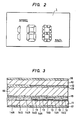
- Fig. 2 shows an example of the display content of a speed indicator using a liquid crystal display device.
- the numeric unit consists of seven segments, which are hereby called "a, b, c, d, e, f and g segments”.
- segment display electrodes 13 are disposed on a glass substrate 11 of a lower plate, and color filters such as red and green filters 14R and 14G are alternately formed on the segment display electrodes 13.
- a flat electrode 12 is disposed on the lower surface of a glass substrate 10 of an upper plate that faces the lower plate glass substrate 11.
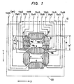
- the flat electrode 12 has a 7-segment shape such as shown in Fig. 1.
- Orientation control films 15 are formed on the color filters 14R, 14G and the flat electrode 12 in order to orient the liquid crystal molecules in a certain predetermined direction, and a liquid crystal material 18 is sealed between them.
- a lower plate polarizer 17 is disposed by an adhesive outside the lower plate glass substrate 11 while an upper plate polarizer 16 is disposed by an adhesive outside the upper plate glass substrate 10.
- the present invention employs an electrode pattern construction such as shown in Fg. 1.
- the pattern represented by solid line indicates the segment display electrode 13 and the pattern represented by dash line does the flat electrode 12.
- the segments a, b, c, d, e, f and g are formed on the segment display electrode 13 by comb tooth-like electrodes that are all coordinated in a longitudinal direction with respect to a display segment.
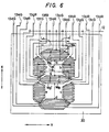
- Fig. 5 is a partial enlarged view of the g segment.
- the comb tooth-like electrode corresponding to the same color in each segment is positioned on the same line in a stripe direction.
- the comb tooth-like electrode of the a segment corresponding to R for example, is disposed on the same line in the longitudinal direction as the comb tooth-like electrodes of the b, c, d, e, f and g segments corresponding to R.
- the pattern display of the liquid crystal display device by the application of the voltage to the electrodes 12, 13 is effected by the peripheral portion of the flat electrode 12, which does not make segment display, rather than the segment display electrode 13, it is generally effective if the occupying area of the flat electrode 12 than the occupying area of the segment display electrode 13 which includes the gap portion between 13gR and 13gG as shown in Fig. 5.
- the flat electrode 12 represented by dash line in Fig. 1 defines the shape of the 7-segment display pattern.
- the segments are connected with one another inside the 7-segment.
- the other segments that can be formed in a size greater than the display segments that is, the a, d and g segments
- either one of the end portions of each segment in its longitudinal direction is used as an extension portion for mutual connection of the electrodes.
- the extension patterns are connected integrally inside an effective display range 20 as the liquid crystal display device (inside one-dot- chain line in Fig. 1) and moreover, while the wiring of the extension pattern of the segment display electrode 13 is outside the effective display range 20 when the lower plate glass substrate and the upper plate glass substrate are superposed with each other.
- connection arrangement described above can prevent turn-on of the turn-off portions due to the crossing of the wirings of the extension patterns of the upper and lower transparent electrodes other than the turn-on shape portions within the effective display range, and can reduce and simplify the wirings.
- the display unit can be driven completely statically and display having high visibility without any dependence on the angle of view can be accomplished.
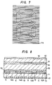
- Fig. 4 shows the case where a color filters 14 are formed on the electrode pattern shown in Fig. 1.
- the red and green stripe-like color filters are alternately formed in the longitudinal direction which is the same direction of the comb tooth-like electrode pattern, and uniformly over the entire surface of the effective display range.
- the entire surface of the effective display range becomes uniform and since the color arrangement of the turn-off segment portion is exactly the same as that of the portions outside the display unit, display having high visibility can be provided.
- Fig. 6 shows the case where the stripe direction of the comb tooth-like electrodes is transverse with respect to the display segments. In this case, all the segment display electrodes 13 are in the transverse direction.
- the shape of the terminal portions of the b, c, e and f segments in Fig. 1 corresponds to the a, d and g segments in Fig. 6, and the end portion of each segment is formed in the transverse direction.
- the shapes of the terminal portions of the a, d and g segments in Fig. 1 correspond to those of the b, c, e and g segments and are formed by the periphery of one side of each segment.
- Fig. 7 shows the case where color filters 14 are formed on the electrode pattern shown in Fig. 6.
- the two stripe-like color filters are formed alternately and uniformly in the transverse direction with respect to the display segment.
- the present invention can drive the display device completely statically, can eliminate the occurrence of turn-on of the electrode patterns other than the pattern of the turn-on portions, and can provide a color liquid crystal display device having high visibility due to the improvement in contrast.
- a segment display electrode 13 is shown disposed on the lower plate glass substrate 11, and stripe-like color filter layers 14R, 14G for producing display colors such as red and green are alternately formed on the segment display electrode 13.
- a stripe-like color filter layer 5 for controlling the background color of the liquid crystal display device 1 is disposed between the color filters 14R and 14G, for example. Since it is not associated with the turn-on segments, the color filter 5 is formed in a range other than the segment display electrode 13.
- An arbitrary color is used for the color filter 5 so that the desired background color of the liquid crystal display device 1 is determined by the combination of the color filters 14R and 14G for producing the turn-on colors.
- the color of the color filter 5 determining the background color is blue. In this case, the background color by the combination of these solors is substantially approximate to white.
- the flat electrode 7 is disposed on the upper plate glass substrate 10 in such a manner as to face the lower plate glass substrate 11.
- the flat electrode 7 has the same of the turn-on segment shown in Fig. 2.
- Orientation control films 15 for orienting the liquid crystal molecules in a certain predetermined direction are formed on the color filters 14R, 14G, on 5 and on the flat electrode 12, respectively, and a liquid crystal material is sealed between these members.
- the lower plate polarizer 17 is bonded outside the lower plate glass substrate 11 while the upper plate polarizer 16 is bonded outside the upper plate glass substrate 10.
- the liquid crystal existing between the mutually overlapping electrodes operates and the color of each color filter 14R, 14G can be seen through.
- the liquid crystal 18 at the other portions is inoperative and can be seen through as the background color other than the color of the tum-on display shape.
- Fig. 9 is a schematic view when the construction of the present invention is viewed from the side of the liquid crystal display surface. This drawing is a partial enlarged view of the g segment shown in Fig. 1. Dash line represents the segment display electrode 13 on the lower plate side. The portion colored by the red filter layer 14R is 13gR and the portion colored by the green filter layer 14G is 13gG. The blue filter layer 5 is formed between the comb tooth-like electrodes 13gR and 13gG.
- the mixed color synthesized by these filter colors is the background color of the liquid crystal display device 1.
- the color filter layer for determining the background color can be formed in addition to the transparent electrodes associated with turn-on so that the tone of the background color can be expressed freely in accordance with a customer's need.
- the color filter layer 5 for determining the background color need not always be disposed between the red filter layer 14R and the green filter layer 14G.
- the color filter layer 5 may be disposed in the sequence of the red filter layer 14R, the green filter layer 14G and then the background color filter layer 5.
- the present invention can accomplish a color liquid display device which can arbitrarily change the background color in accordance with a customer's need and has high visibility.
Landscapes
- Physics & Mathematics (AREA)
- Nonlinear Science (AREA)
- Mathematical Physics (AREA)
- Chemical & Material Sciences (AREA)
- Crystallography & Structural Chemistry (AREA)
- General Physics & Mathematics (AREA)
- Optics & Photonics (AREA)
- Geometry (AREA)
- Liquid Crystal (AREA)
Claims (6)
dadurch gekennzeichnet, daß
Applications Claiming Priority (4)
| Application Number | Priority Date | Filing Date | Title |
|---|---|---|---|
| JP60223627A JPS6283721A (ja) | 1985-10-09 | 1985-10-09 | カラ−液晶表示素子 |
| JP223627/85 | 1985-10-09 | ||
| JP276821/85 | 1985-12-11 | ||
| JP60276821A JPS62136620A (ja) | 1985-12-11 | 1985-12-11 | 液晶表示素子 |
Publications (3)
| Publication Number | Publication Date |
|---|---|
| EP0219064A2 EP0219064A2 (de) | 1987-04-22 |
| EP0219064A3 EP0219064A3 (en) | 1988-10-12 |
| EP0219064B1 true EP0219064B1 (de) | 1990-04-25 |
Family
ID=26525600
Family Applications (1)
| Application Number | Title | Priority Date | Filing Date |
|---|---|---|---|
| EP86113999A Expired - Lifetime EP0219064B1 (de) | 1985-10-09 | 1986-10-09 | Farbflüssigkristall-Anzeigevorrichtung |
Country Status (4)
| Country | Link |
|---|---|
| US (1) | US4697886A (de) |
| EP (1) | EP0219064B1 (de) |
| KR (1) | KR910007013B1 (de) |
| DE (1) | DE3670700D1 (de) |
Families Citing this family (10)
| Publication number | Priority date | Publication date | Assignee | Title |
|---|---|---|---|---|
| NL8702508A (nl) * | 1986-10-22 | 1988-05-16 | Toppan Printing Co Ltd | Electrodeplaat voor kleurenweergeefinrichting. |
| DE3705259A1 (de) * | 1987-02-19 | 1988-09-01 | Vdo Schindling | Fluessigkristallzelle |
| FR2618008B1 (fr) * | 1987-07-07 | 1989-10-20 | Commissariat Energie Atomique | Ecran polychrome |
| JPS6442633A (en) * | 1987-08-10 | 1989-02-14 | Koito Mfg Co Ltd | Liquid crystal display device for color display |
| JP2594985B2 (ja) * | 1987-11-24 | 1997-03-26 | 株式会社日立製作所 | 液晶表示素子 |
| JPH04174417A (ja) * | 1990-11-07 | 1992-06-22 | Sharp Corp | カラー液晶表示装置 |
| KR950009318A (ko) * | 1993-09-03 | 1995-04-21 | 미타라이 하지메 | 표시장치 |
| US6147666A (en) * | 1997-12-22 | 2000-11-14 | Yaniv; Zvi | Multipole liquid crystal display |
| DE60331481D1 (de) * | 2003-09-04 | 2010-04-08 | Fujitsu Ltd | Ic-karte |
| USD614689S1 (en) | 2008-09-02 | 2010-04-27 | Erbe Elektromedizin Gmbh | Multi segment display |
Family Cites Families (9)
| Publication number | Priority date | Publication date | Assignee | Title |
|---|---|---|---|---|
| CA760824A (en) * | 1967-06-13 | O. Hoffmann Gotfred | Transfer counter | |
| CA995783A (en) * | 1971-06-04 | 1976-08-24 | Ise Electronics Corporation | Liquid crystal display device |
| US3807831A (en) * | 1972-06-20 | 1974-04-30 | Beckman Instruments Inc | Liquid crystal display apparatus |
| DD100605A1 (de) * | 1972-11-06 | 1973-09-20 | ||
| JPS5436750A (en) * | 1977-08-26 | 1979-03-17 | Citizen Watch Co Ltd | Liquid crystal display device with comb-tooth shaped electrode |
| GB2024443B (en) * | 1978-03-22 | 1982-06-23 | Marconi Co Ltd | Coloured display systems |
| JPS59136718A (ja) * | 1983-01-26 | 1984-08-06 | Mitsubishi Electric Corp | 液晶表示素子 |
| JPS59222877A (ja) * | 1983-06-01 | 1984-12-14 | 大日本スクリ−ン製造株式会社 | 多色液晶表示素子 |
| JPS60260921A (ja) * | 1984-06-08 | 1985-12-24 | Hitachi Ltd | 液晶表示装置 |
-
1986
- 1986-10-07 KR KR1019860008377A patent/KR910007013B1/ko not_active Expired
- 1986-10-08 US US06/916,698 patent/US4697886A/en not_active Expired - Fee Related
- 1986-10-09 EP EP86113999A patent/EP0219064B1/de not_active Expired - Lifetime
- 1986-10-09 DE DE8686113999T patent/DE3670700D1/de not_active Expired - Lifetime
Also Published As
| Publication number | Publication date |
|---|---|
| DE3670700D1 (de) | 1990-05-31 |
| US4697886A (en) | 1987-10-06 |
| KR910007013B1 (ko) | 1991-09-14 |
| KR870004395A (ko) | 1987-05-09 |
| EP0219064A2 (de) | 1987-04-22 |
| EP0219064A3 (en) | 1988-10-12 |
Similar Documents
| Publication | Publication Date | Title |
|---|---|---|
| EP0715202B1 (de) | Anzeigevorrichtung | |
| US4902103A (en) | Color liquid-crystal display unit with electrodes interleaved in vertical and horizontal directions | |
| EP0219064B1 (de) | Farbflüssigkristall-Anzeigevorrichtung | |
| KR970016724A (ko) | 오버랩하는 컬러 필터를 갖는 액정 디스플레이 장치 | |
| US5233449A (en) | Liquid-crystal color display with comb-shaped pixel electrodes partially overlapping at the electrode ends | |
| CA1258312A (en) | Liquid crystal color display apparatus | |
| US4957350A (en) | Liquid crystal display device | |
| JPS5885418A (ja) | 受動型マルチカラ−表示装置 | |
| KR100745944B1 (ko) | 전기 광학 장치 및 전자기기 | |
| KR100997961B1 (ko) | 액정 표시 장치 | |
| CN114779519A (zh) | 时序液晶显示面板及显示装置 | |
| JP3776184B2 (ja) | 液晶表示パネル | |
| JPS61239220A (ja) | 液晶表示素子 | |
| JPS6283721A (ja) | カラ−液晶表示素子 | |
| JPS61102627A (ja) | カラ−液晶表示装置 | |
| JPS59159131A (ja) | 液晶表示装置 | |
| JPS6291917A (ja) | 液晶表示装置 | |
| JPH075466Y2 (ja) | 電気泳動表示素子 | |
| JP3007991B2 (ja) | 多色液晶表示装置の駆動方法 | |
| JPH01319093A (ja) | 液晶表示装置 | |
| JPS6259924A (ja) | マトリクス型液晶表示装置 | |
| JPH0350493Y2 (de) | ||
| JP2001337625A (ja) | 表示素子 | |
| JPS62136620A (ja) | 液晶表示素子 | |
| JPH083588B2 (ja) | カラー表示液晶表示装置 |
Legal Events
| Date | Code | Title | Description |
|---|---|---|---|
| PUAI | Public reference made under article 153(3) epc to a published international application that has entered the european phase |
Free format text: ORIGINAL CODE: 0009012 |
|
| AK | Designated contracting states |
Kind code of ref document: A2 Designated state(s): DE GB |
|
| PUAL | Search report despatched |
Free format text: ORIGINAL CODE: 0009013 |
|
| AK | Designated contracting states |
Kind code of ref document: A3 Designated state(s): DE GB |
|
| 17P | Request for examination filed |
Effective date: 19881027 |
|
| 17Q | First examination report despatched |
Effective date: 19890517 |
|
| GRAA | (expected) grant |
Free format text: ORIGINAL CODE: 0009210 |
|
| AK | Designated contracting states |
Kind code of ref document: B1 Designated state(s): DE GB |
|
| REF | Corresponds to: |
Ref document number: 3670700 Country of ref document: DE Date of ref document: 19900531 |
|
| PLBE | No opposition filed within time limit |
Free format text: ORIGINAL CODE: 0009261 |
|
| STAA | Information on the status of an ep patent application or granted ep patent |
Free format text: STATUS: NO OPPOSITION FILED WITHIN TIME LIMIT |
|
| 26N | No opposition filed | ||
| PGFP | Annual fee paid to national office [announced via postgrant information from national office to epo] |
Ref country code: GB Payment date: 19910805 Year of fee payment: 6 |
|
| PGFP | Annual fee paid to national office [announced via postgrant information from national office to epo] |
Ref country code: DE Payment date: 19911118 Year of fee payment: 6 |
|
| PG25 | Lapsed in a contracting state [announced via postgrant information from national office to epo] |
Ref country code: GB Effective date: 19921009 |
|
| GBPC | Gb: european patent ceased through non-payment of renewal fee |
Effective date: 19921009 |
|
| PG25 | Lapsed in a contracting state [announced via postgrant information from national office to epo] |
Ref country code: DE Effective date: 19930701 |