EP0218744A1 - Device for making a cylindrical hole through a wall, in particular for masonry - Google Patents
Device for making a cylindrical hole through a wall, in particular for masonry Download PDFInfo
- Publication number
- EP0218744A1 EP0218744A1 EP85113063A EP85113063A EP0218744A1 EP 0218744 A1 EP0218744 A1 EP 0218744A1 EP 85113063 A EP85113063 A EP 85113063A EP 85113063 A EP85113063 A EP 85113063A EP 0218744 A1 EP0218744 A1 EP 0218744A1
- Authority
- EP
- European Patent Office
- Prior art keywords
- sleeve
- drill
- hollow
- wall
- hollow chamber
- Prior art date
- Legal status (The legal status is an assumption and is not a legal conclusion. Google has not performed a legal analysis and makes no representation as to the accuracy of the status listed.)
- Granted
Links
Images
Classifications
-
- B—PERFORMING OPERATIONS; TRANSPORTING
- B23—MACHINE TOOLS; METAL-WORKING NOT OTHERWISE PROVIDED FOR
- B23Q—DETAILS, COMPONENTS, OR ACCESSORIES FOR MACHINE TOOLS, e.g. ARRANGEMENTS FOR COPYING OR CONTROLLING; MACHINE TOOLS IN GENERAL CHARACTERISED BY THE CONSTRUCTION OF PARTICULAR DETAILS OR COMPONENTS; COMBINATIONS OR ASSOCIATIONS OF METAL-WORKING MACHINES, NOT DIRECTED TO A PARTICULAR RESULT
- B23Q11/00—Accessories fitted to machine tools for keeping tools or parts of the machine in good working condition or for cooling work; Safety devices specially combined with or arranged in, or specially adapted for use in connection with, machine tools
- B23Q11/0042—Devices for removing chips
- B23Q11/0046—Devices for removing chips by sucking
-
- B—PERFORMING OPERATIONS; TRANSPORTING
- B23—MACHINE TOOLS; METAL-WORKING NOT OTHERWISE PROVIDED FOR
- B23B—TURNING; BORING
- B23B51/00—Tools for drilling machines
- B23B51/04—Drills for trepanning
- B23B51/042—Drills for trepanning with lubricating or cooling equipment
-
- B—PERFORMING OPERATIONS; TRANSPORTING
- B28—WORKING CEMENT, CLAY, OR STONE
- B28D—WORKING STONE OR STONE-LIKE MATERIALS
- B28D1/00—Working stone or stone-like materials, e.g. brick, concrete or glass, not provided for elsewhere; Machines, devices, tools therefor
- B28D1/02—Working stone or stone-like materials, e.g. brick, concrete or glass, not provided for elsewhere; Machines, devices, tools therefor by sawing
- B28D1/04—Working stone or stone-like materials, e.g. brick, concrete or glass, not provided for elsewhere; Machines, devices, tools therefor by sawing with circular or cylindrical saw-blades or saw-discs
- B28D1/041—Working stone or stone-like materials, e.g. brick, concrete or glass, not provided for elsewhere; Machines, devices, tools therefor by sawing with circular or cylindrical saw-blades or saw-discs with cylinder saws, e.g. trepanning; saw cylinders, e.g. having their cutting rim equipped with abrasive particles
Definitions
- the invention relates to a device for producing a circular-cylindrical breakthrough in a wall, in particular masonry wall, - with a hollow boring tool which has a drill bit formed by cutting teeth at the free end of a drill sleeve and is drivable by a rotary drill.
- the drill sleeve also has a limited length, so that after reaching a certain drilling depth interrupted drilling, the hollow boring tool retracted, the stalled hollow cylindrical core must be destroyed and removed, whereupon the hollow boring tool can be re-introduced and put into operation. All this is not only cumbersome, but because of the considerable amount of dust that is inevitably discharged to the environment and this dirty to a considerable extent, also annoying and often - such. B. in inhabited rooms - unreasonable. Although are also Diamantkronenboh rer known with water flushing and cooling, but these can certainly not be used in inhabited rooms and especially on wallpapered walls.
- the invention has for its object to develop a device of the type mentioned so that the breakthrough can be made in one operation without the polluting dust environment.
- the hollow drilling tool consists of a innenzentri mecanicslosen core drill with respect to the drill sleeve radially inwardly and outwardly projecting cutting teeth and with at least one remote in the region of the drill bit end of the drill sleeve air inlet opening and that the core drill with its sleeve longitudinally displaceable and rotatably but substantially pressure-tight in a hollow chamber sleeve with sealing Wandungsstromrand and is arranged connected to a suction chamber outlet.
- a cuttings channel which has a hollow cylindrical section extending along the inner lateral surface of the drill sleeve and a hollow cylindrical section extending along the outer lateral surface of the drill sleeve, these two hollow cylindrical sections being connected to one another by the gaps existing between the cutting teeth.
- the suction device is provided with a filter for collecting the sucked cuttings.
- the axial forces to be used for drilling are very low, because a centering inner drill is missing and, as a result of the vacuum flushing, no friction occurs between the drill sleeve and the wall. After completion of the drilling process and removal of the device, the cylindrical wall drill core can be removed cleanly.
- the drill sleeve preferably has a smooth-surfaced inner and outer sheath to promote the transport of the cuttings through the air flow.
- the measure aims that the centrally mounted cutting teeth have a radial extent corresponding to up to four times the wall thickness of the drill sleeve.
- the drill sleeve will of course give a length which corresponds at least to the largest thickness of the wall to be drilled; However, in order to avoid unnecessary excess lengths, it is advisable to arrange the air inlet opening or openings in the bottom of the drill sleeve facing away from the drill bit.
- the core drill can readily be considered an integral part of the Be executed rotary drilling; However, preferred is an embodiment in which the core drill with rear clamping shaft is designed for a chuck of the rotary drill. Moreover, it is recommended that the hollow boring tool and the attached rotary drilling machine, which expediently consists of a rotary impact boring machine, to guide against the hollow chamber sleeve.
- the hollow chamber sleeve preferably has a guide at least for the drill sleeve; this can advantageously consist of attached to the hollow chamber cuff centering rollers.
- the hollow chamber sleeve and the drill sleeve are sealed in the simplest case by an on the one hand to the hollow chamber sleeve attached, on the other hand, applied to the drill sleeve annular lip seal against each other.
- the hollow chamber sleeve is expediently designed as a rigid component, it is recommended to form the sealing Wandungsstromrand of a resilient sealing profile.
- the sealing profile has a suction cup cross-section.
- the chamber outlet is expediently designed as a connecting piece for the suction device. If the device for the production of breakthroughs with a particularly large diameter set up and for this reason bulky and unwieldy, it is recommended to provide the hollow chamber sleeve with a chassis.
- the device operates with a hollow boring tool, which has a drill bit 3 formed by cutting teeth 1 at the free end of a drill sleeve 2 and can be driven by a rotary drill, not shown.
- the hollow boring tool consists of a innenzentri mecanicslosen core drill 4 with respect to the drill sleeve 2 radially inwardly and outwardly projecting cutting teeth 1.
- the core drill 4 is longitudinally displaceable with its drilling sleeve 2 and therefore, but arranged substantially pressure-tight in a hollow chamber sleeve 6 with sealing Wandungsstromrand 7 and connectable to a suction chamber outlet 8.
- the drill sleeve 2 has a smooth-surfaced inner and outer sheath.
- the centrally mounted cutting teeth 1 have a radial extent, which corresponds approximately to four times the wall thickness of the drill sleeve 2.
- the air inlet openings 5 are arranged in the drill bit 3 facing away from the bottom 9 of the drill sleeve 2. From the figure it is readily apparent that the core drill 4 is executed with rear clamping shaft 10 for a chuck of the rotary drilling, which is suitably designed as a rotary hammer drill.
- the hollow chamber sleeve 6 has a guide at least for the drill sleeve 2.
- the guide initially consists of attached to the hollow chamber sleeve 6 centering rollers 11 for the sleeve 2.
- Schematically indicated is another guide, namely axial guide 12 for the rotary drill.
- the hollow chamber sleeve 6 and the sleeve 2 are in any case sealed against each other by a lip seal 13, on the one hand the hollow chamber sleeve 6 is attached and on the other hand bears against the drill sleeve 2.
- the sealing Wandungsstromrand 7 is formed by a resilient sealing profile with Saugnapfähnlichem cross-section.
- the chamber connection 8 is designed as a connecting piece.
- the hollow chamber sleeve 6 is still provided with a chassis, which is not shown in detail.
- the hollow chamber sleeve 6 is attached with the core drill 4 held therein at the appropriate location on the wall 14. If now the suction device connected to the chamber outlet 8 is put into operation, then the hollow chamber sleeve 6 sucks firmly against the wall 14, whereupon the rotary impact boring machine can be put into operation. It is now in the wall 14 of the core drill 4, a hollow cylindrical recess 15 is generated. The dust released by the cutting teeth 1 is sucked through the air, which flows through the air inlet openings 5 into the drill sleeve 2 and from there into the hollow cylindrical recess 15, via the chamber outlet 8. If the wall 14 completely pierced, the dust-free core 16 can be easily removed.
Abstract
Description
Die Erfindung betrifft eine Vorrichtung zum Herstellen eines kreiszylindrischen Durchbruches in einer Wandung, insbesondere Mauerwerkswandung , - mit einem Hohlbohrwerkzeug, welches eine von Schneidzähnen am freien Ende einer Bohrhülse gebildete Bohrkrone aufweist und von einem Drehbohrwerk antreibbar ist.The invention relates to a device for producing a circular-cylindrical breakthrough in a wall, in particular masonry wall, - with a hollow boring tool which has a drill bit formed by cutting teeth at the free end of a drill sleeve and is drivable by a rotary drill.
Bei aus der Praxis bekannten, druckschriftlich nicht näher belegten Vorrichtungen der genannten Art, die man beispielsweise zum nachträglichen Herstellen von Belüftungsöffnungen, Abzügen und dergleichen einsetzt, weist das Hohlbohrwerkzeug in der Bohrhülse noch einen zentralen, gegenüber der Bohrkrone vorstehenden Innenzentrierungsbohrer auf. Der beim Bohren anfallende Bohrstaub wird über eine im Außenmantel der Bohrhülse vorgesehene Abraumspirale gleichsam selbstätig weggefördert, was aufgrund der zwischen Bohrhülse, Bohrstaub und Wandung auftretenden Reibungskräfte allerdings nur bis zu einer bestimmten Tiefe gelingt. Aus diesem Grund weist die Bohrhülse auch eine beschränke Länge auf, so daß nach Erreichen einer bestimmten Bohrtiefe das Bohren unterbrochen, das Hohlbohrwerkzeug zurückgezogen, der stehengebliebene hohlzylindrische Bohrkern zerstört und entnommen werden muß, woraufhin das Hohlbohrwerkzeug erneut eingeführt und in Betrieb gesetzt werden kann. Alles das ist nicht nur umständlich, sondern wegen des erheblichen Anfalles an Staub, der unvermeidbar an die Umgebung abgegeben wird und diese in erheblichem Maße verschmutzt, auch lästig und oftmals - so z. B. in bewohnten Räumen - nicht zumutbar. Zwar sind auch Diamantkronenboh rer mit Wasserspülung und -kühlung bekannt, diese können aber in bewohnten Räumen und insbesondere an tapezierten Wänden erst recht nicht eingesetzt werden.In known from practice, printed documents unspecified devices of the type mentioned, which is used, for example, for the subsequent production of ventilation openings, fume cupboards and the like, the Hohlbohrwerkzeug in the drill sleeve still has a central, opposite the drill bit projecting Innenzentrierungsbohrer on. The drilling dust accumulated during drilling is conveyed away as it were via an overflow spiral provided in the outer casing of the drill sleeve, which however only succeeds to a certain depth due to the frictional forces occurring between the drill sleeve, the drilling dust and the wall. For this reason, the drill sleeve also has a limited length, so that after reaching a certain drilling depth interrupted drilling, the hollow boring tool retracted, the stalled hollow cylindrical core must be destroyed and removed, whereupon the hollow boring tool can be re-introduced and put into operation. All this is not only cumbersome, but because of the considerable amount of dust that is inevitably discharged to the environment and this dirty to a considerable extent, also annoying and often - such. B. in inhabited rooms - unreasonable. Although are also Diamantkronenboh rer known with water flushing and cooling, but these can certainly not be used in inhabited rooms and especially on wallpapered walls.
Der Erfindung liegt die Aufgabe zugrunde, eine Vorrichtung der eingangs genannten Art so weiter zu entwickeln, daß der Durchbruch in einem Arbeitsgang ohne die Umgebung verschmutzenden Staubanfall hergestellt werden kann.The invention has for its object to develop a device of the type mentioned so that the breakthrough can be made in one operation without the polluting dust environment.
Die erfindungsgemäße Lösung dieser Aufgabe besteht darin, daß das Hohlbohrwerkzeug aus einem innenzentrierungslosen Kernbohrer mit gegenüber der Bohrhülse radial nach innen sowie außen vorkragenden Schneidzähnen und mit wenigstens einer im Bereich des der Bohrkrone abgewandten Endes der Bohrhülse vorgesehenen Luftzutrittsöffnung besteht und daß der Kernbohrer mit seiner Bohrhülse längsverschiebbar und drehbar aber im wesentlichen druckdicht in einer Hohlkammermanschette mit dichtendem Wandungsanlagerand und mit an eine Absaugeinrichtung anschließbarem Kammerauslaß angeordnet ist.The achievement of this task is that the hollow drilling tool consists of a innenzentrierungslosen core drill with respect to the drill sleeve radially inwardly and outwardly projecting cutting teeth and with at least one remote in the region of the drill bit end of the drill sleeve air inlet opening and that the core drill with its sleeve longitudinally displaceable and rotatably but substantially pressure-tight in a hollow chamber sleeve with sealing Wandungsanlagerand and is arranged connected to a suction chamber outlet.
Durch die radialen Vorkragungen der Schneidzähne wird beim Bohren ein Bohrgutkanal erzeugt, der einen längs der Innenmantelfläche der Bohrhülse verlaufenden Hohlzylinderabschnitt und einen längs der Außenmantelfläche der Bohrhülse verlaufenden Hohlzylinderabschnitt aufweist, wobei diese beiden Hohlzylinderabschnitte durch die zwischen den Schneidzähnen vorhandenen Lücken miteinander verbunden sind. Durch die über den Kammerauslaß an die Hohlkammermanschette angeschlossene Absaugeinrichtung wird nun eine Luftströmung erzwungen, die durch die Luftzutrittsöffnung, die Bohrhülse, den vorgenannten Bohrgutkanal, die Hohlkammermanschette sowie den Kammerauslaß verläuft und zugleich die Schneidzähne kühlt sowie das Bohrgut mit sich reißt. Zufolge der zwischen Bohrhülse und Hohlkammermanschette verwirklichten Abdichtung und des dichtenden Wandungsanlagerandes kann diese Luftströmung auch nicht durch unerwünschte Luftnebenströmungen unterbrochen werden. Vorteilhaft ist jedenfalls, daß der Durchbruch in einem einzigen Bohrvorgang hergestellt werden kann, ohne daß die Umgebung durch Staub verschmutzt wird. Es versteht sich hierbei von selbst, daß die Absaugeinrichtung mit einem Filter zum Auffangen des abgesaugten Bohrgutes versehen ist. Die zum Bohren aufzuwendenden Axialkräfte sind sehr gering, weil ein zentrierender Innenbohrer fehlt und zufolge der Unterdruckspülung keinerlei Reibung zwischen Bohrhülse sowie Wandung auftritt. Nach Beendigung des Bohrvorganges und Entfernen der Vorrichtung kann der zylindrische wandungsbohrkern sauber entnommen werden.As a result of the radial protrusions of the cutting teeth, during drilling a cuttings channel is produced which has a hollow cylindrical section extending along the inner lateral surface of the drill sleeve and a hollow cylindrical section extending along the outer lateral surface of the drill sleeve, these two hollow cylindrical sections being connected to one another by the gaps existing between the cutting teeth. By connected via the chamber outlet to the hollow chamber sleeve suction device now an air flow is forced through the air inlet opening, the drill sleeve, the aforementioned Bohrgutkanal, the Cavity sleeve and the chamber outlet runs and at the same time cools the cutting teeth and rips the cuttings with it. As a result of the sealing realized between the drill sleeve and the hollow chamber sleeve and the sealing Wandungsanlagerandes this air flow can not be interrupted by unwanted air bypasses. It is advantageous in any case that the breakthrough can be made in a single drilling without the environment being polluted by dust. It goes without saying that the suction device is provided with a filter for collecting the sucked cuttings. The axial forces to be used for drilling are very low, because a centering inner drill is missing and, as a result of the vacuum flushing, no friction occurs between the drill sleeve and the wall. After completion of the drilling process and removal of the device, the cylindrical wall drill core can be removed cleanly.
Für die weitere Ausgestaltung bestehen im Rahmen der Erfindung mehrere Möglichkeiten. So weist die Bohrhülse vorzugsweise einen glattflächigen Innen- und Außenmantel auf, um den Transport des Bohrgutes durch die Luftströmung zu begünstigen. In die gleiche Richtung zielt auch die Maßnahme, daß die mittig aufgesetzten Schneidzähne eine radiale Erstreckung aufweisen, die dem bis zu Vierfachen der Wandstärke der Bohrhülse entspricht. Der Bohrhülse wird man selbstverständlich eine Länge geben, die zumindest der größten Dicke der zu durchbohrenden Wandung entspricht; um hierbei aber unnötige Überlängen zu vermeiden, empfiehlt es sich, die Luftzutrittsöffnung bzw. -öffnungen in dem der Bohrkrone abgewandten Boden der Bohrhülse anzuordnen. Der Kernbohrer kann ohne weiteres als integraler Bestandteil des Drehbohrwerkes ausgeführt sein; bevorzugt ist jedoch eine Ausführungsform, bei der der Kernbohrer mit rückwärtigem Spannschaft für ein Spannfutter des Drehbohrwerkes ausgeführt ist. Im übrigen empfiehlt es sich, das Hohlbohrwerkzeug und das daran angeschlossene Drehbohrwerk, das zweckmäßigerweise aus einem Drehschlagbohrwerk besteht, gegenüber der Hohlkammermanschette zu führen. Zu diesem Zweck weist die Hohlkammermanschette vorzugsweise eine Führung zumindest für die Bohrhülse auf; diese kann vorteilhaft aus an der Hohlkammermanschette befestigten Zentrierungsrollen bestehen. Die Hohlkammermanschette und die Bohrhülse sind im einfachsten Fall durch eine einerseits an der Hohlkammermanschette befestigte, andererseits an der Bohrhülse anliegende ringförmige Lippendichtung gegeneinander abgedichtet. Da die Hohlkammermanschette zweckmäßigerweise als starres Bauteil ausgeführt ist, empfiehlt es sich, den dichtenden Wandungsanlagerand von einem nachgiebigen Dichtungsprofil zu bilden. Vorzugsweise weist das Dichtungsprofil einen Saugnapfquerschnitt auf. Der Kammerauslaß wird zweckmäßigerweise als Anschlußstutzen für die Absaugeinrichtung ausgebildet. Sofern die Vorrichtung für das Herstellen von Durchbrüchen mit besonders großem Durchmesser eingerichtet und aus diesem Grunde großbauend sowie unhandlich ist, empfiehlt es sich, die Hohlkammermanschette mit einem Fahrwerk zu versehen.For the further embodiment, there are several possibilities within the scope of the invention. Thus, the drill sleeve preferably has a smooth-surfaced inner and outer sheath to promote the transport of the cuttings through the air flow. In the same direction, the measure aims that the centrally mounted cutting teeth have a radial extent corresponding to up to four times the wall thickness of the drill sleeve. The drill sleeve will of course give a length which corresponds at least to the largest thickness of the wall to be drilled; However, in order to avoid unnecessary excess lengths, it is advisable to arrange the air inlet opening or openings in the bottom of the drill sleeve facing away from the drill bit. The core drill can readily be considered an integral part of the Be executed rotary drilling; However, preferred is an embodiment in which the core drill with rear clamping shaft is designed for a chuck of the rotary drill. Moreover, it is recommended that the hollow boring tool and the attached rotary drilling machine, which expediently consists of a rotary impact boring machine, to guide against the hollow chamber sleeve. For this purpose, the hollow chamber sleeve preferably has a guide at least for the drill sleeve; this can advantageously consist of attached to the hollow chamber cuff centering rollers. The hollow chamber sleeve and the drill sleeve are sealed in the simplest case by an on the one hand to the hollow chamber sleeve attached, on the other hand, applied to the drill sleeve annular lip seal against each other. Since the hollow chamber sleeve is expediently designed as a rigid component, it is recommended to form the sealing Wandungsanlagerand of a resilient sealing profile. Preferably, the sealing profile has a suction cup cross-section. The chamber outlet is expediently designed as a connecting piece for the suction device. If the device for the production of breakthroughs with a particularly large diameter set up and for this reason bulky and unwieldy, it is recommended to provide the hollow chamber sleeve with a chassis.
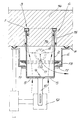
Im folgenden wird die Erfindung anhand einer ein Ausführungsbeispiel darstellenden Zeichnung näher erläutert, deren einzige Zeichnung schematisch im Längsschnitt eine Vorrichtung zum Herstellen eines kreiszylindrischen Durchbruches in einer Wandung, insbesondere Mauerwerkswandung, zeigt.In the following the invention will be explained in more detail with reference to a drawing illustrating an embodiment whose single drawing shows schematically in longitudinal section a device for producing a circular-cylindrical breakthrough in a wall, in particular Mauerwerkswandung.
Die Vorrichtung arbeitet mit einem Hohlbohrwerkzeug, welches eine von Schneidzähnen 1 am freien Ende einer Bohrhülse 2 gebildete Bohrkrone 3 aufweist und von einem nicht dargestellten Drehbohrwerk antreibbar ist. Das Hohlbohrwerkzeug besteht aus einem innenzentrierungslosen Kernbohrer 4 mit gegenüber der Bohrhülse 2 radial nach innen sowie außen vorkragenden Schneidzähnen 1. Im Bereich des der Bohrkrone 3 abgewandten Endes der Bohrhülse 2 ist wenigstens eine Luftzutrittsöffnung 5 vorgesehen. Der Kernbohrer 4 ist mit seiner Bohrhülse 2 längsverschiebbar und daher, aber im wesentlichen Druckdicht in einer Hohlkammermanschette 6 mit dichtendem Wandungsanlagerand 7 und mit an einer Absaugeinrichtung anschließbarem Kammerauslaß 8 angeordnet.The device operates with a hollow boring tool, which has a
Die Bohrhülse 2 weist einen glattflächigen Innen- und Außenmantel auf. Die mittig aufgesetzten Schneidzähne 1 weisen eine radiale Erstreckung auf, die etwa dem Vierfachen der Wandungsstärke der Bohrhülse 2 entspricht. Die Luftzutrittsöffnungen 5 sind in dem der Bohrkrone 3 abgewandten Boden 9 der Bohrhülse 2 angeordnet. Aus der Figur entnimmt man ohne weiteres, daß der Kernbohrer 4 mit rückwärtigem Spannschaft 10 für ein Spannfutter des Drehbohrwerkes ausgeführt ist, das zweckmäßigerweise als Drehschlagbohrwerk ausgebildet ist.The drill sleeve 2 has a smooth-surfaced inner and outer sheath. The centrally mounted cutting teeth 1 have a radial extent, which corresponds approximately to four times the wall thickness of the drill sleeve 2. The
Die Hohlkammermanschette 6 weist eine Führung zumindest für die Bohrhülse 2 auf. Die Führung besteht zunächst aus an der Hohlkammermanschette 6 befestigten Zentrierungsrollen 11 für die Bohrhülse 2. Schematisch angedeutet ist eine weitere Führung, und zwar Axialführung 12 für das Drehbohrwerk. Die Hohlkammermanschette 6 und die Bohrhülse 2 sind jedenfalls durch eine Lippendichtung 13 gegeneinander abgedichtet, die einerseits an der Hohlkammermanschette 6 befestigt ist und andererseits an der Bohrhülse 2 anliegt. Der dichtende Wandungsanlagerand 7 ist von einem nachgiebigen Dichtungsprofil mit saugnapfähnlichem Querschnitt gebildet. Der Kammeranschluß 8 ist als Anschlußstutzen ausgebildet. Die Hohlkammermanschette 6 ist noch mit einem Fahrwerk versehen, was im einzelnen aber nicht dargestellt ist.The hollow chamber sleeve 6 has a guide at least for the drill sleeve 2. The guide initially consists of attached to the hollow chamber sleeve 6
Zum Herstellen eines Durchbruches in einer Mauerwerkswandung 14 wird die Hohlkammermanschette 6 mit dem darin gehaltenen Kernbohrer 4 an der entsprechenden Stelle an die Wandung 14 angesetzt. Wird nun die an den Kammerauslaß 8 angeschlossene Absaugeinrichtung in Betrieb gesetzt, so saugt sich die Hohlkammermanschette 6 an der Wandung 14 fest an, woraufhin das Drehschlagbohrwerk in Betrieb gesetzt werden kann. Es wird nunmehr in der Wandung 14 vom Kernbohrer 4 eine hohlzylindrische Ausnehmung 15 erzeugt. Der von den Schneidzähnen 1 freigesetzte Bohrstaub wird durch die Luft, die über die Luftzutrittsöffnungen 5 in die Bohrhülse 2 und von dort in die hohlzylindrische Ausnehmung 15 einströmt, über den Kammerauslaß 8 abgesaugt. Ist die Wandung 14 vollkommen durchbohrt, kann der staubfreie Bohrkern 16 ohne weiteres entfernt werden.To produce a breakthrough in a
Claims (13)
Priority Applications (3)
| Application Number | Priority Date | Filing Date | Title |
|---|---|---|---|
| EP85113063A EP0218744B1 (en) | 1985-10-15 | 1985-10-15 | Device for making a cylindrical hole through a wall, in particular for masonry |
| DE8585113063T DE3567165D1 (en) | 1985-10-15 | 1985-10-15 | Device for making a cylindrical hole through a wall, in particular for masonry |
| AT85113063T ATE39643T1 (en) | 1985-10-15 | 1985-10-15 | DEVICE FOR CREATING A CIRCULAR CYLINDRICAL OPENING IN A WALL, IN PARTICULAR MASONRY WALL. |
Applications Claiming Priority (1)
| Application Number | Priority Date | Filing Date | Title |
|---|---|---|---|
| EP85113063A EP0218744B1 (en) | 1985-10-15 | 1985-10-15 | Device for making a cylindrical hole through a wall, in particular for masonry |
Publications (2)
| Publication Number | Publication Date |
|---|---|
| EP0218744A1 true EP0218744A1 (en) | 1987-04-22 |
| EP0218744B1 EP0218744B1 (en) | 1989-01-04 |
Family
ID=8193829
Family Applications (1)
| Application Number | Title | Priority Date | Filing Date |
|---|---|---|---|
| EP85113063A Expired EP0218744B1 (en) | 1985-10-15 | 1985-10-15 | Device for making a cylindrical hole through a wall, in particular for masonry |
Country Status (3)
| Country | Link |
|---|---|
| EP (1) | EP0218744B1 (en) |
| AT (1) | ATE39643T1 (en) |
| DE (1) | DE3567165D1 (en) |
Cited By (6)
| Publication number | Priority date | Publication date | Assignee | Title |
|---|---|---|---|---|
| WO1993016818A1 (en) * | 1992-02-19 | 1993-09-02 | Keith David Dungate | Method and apparatus for drilling into fibrous materials, whereby dust is extracted and the surface of the bore is sealed |
| EP0783933A1 (en) * | 1996-01-12 | 1997-07-16 | HILTI Aktiengesellschaft | Drilling or chiseling tool |
| EP1593447A1 (en) * | 2004-05-06 | 2005-11-09 | HILTI Aktiengesellschaft | Dust collector for a core drill |
| EP2383072A1 (en) * | 2010-04-28 | 2011-11-02 | HILTI Aktiengesellschaft | drilling tool |
| CN103616329A (en) * | 2013-11-18 | 2014-03-05 | 陈振华 | Method for probing structure condition and outline size of invisible part of brickwork by deep small-aperture drilling machine |
| WO2023083994A1 (en) * | 2021-11-11 | 2023-05-19 | Scherer Engineering Gmbh | Opening device |
Citations (8)
| Publication number | Priority date | Publication date | Assignee | Title |
|---|---|---|---|---|
| US2879035A (en) * | 1957-04-29 | 1959-03-24 | Carl V Tilden | Drilling apparatus |
| US3033298A (en) * | 1961-05-11 | 1962-05-08 | Bert E Johnson | Sludge removal bonnet for core drills and the like |
| AT230252B (en) * | 1961-11-30 | 1963-11-25 | Schaerdinger Granit Ind Ges M | Dust extractor for machine-operated hammers or the like for stone processing |
| US3351143A (en) * | 1965-06-01 | 1967-11-07 | Alvin V Seibold | Concrete drill bit guide and dust remover |
| US3788423A (en) * | 1972-06-07 | 1974-01-29 | Allied Chem | Plenum chamber |
| DE2912396A1 (en) * | 1979-03-29 | 1980-10-09 | Guergen Karl Heinz | Dust collector for masonry drill - has air blown into hole via bit and dust collected in enclosing resilient sleeve |
| DE8200668U1 (en) * | 1982-01-14 | 1982-06-24 | Norton Co., 01606 Worcester, Mass. | DRILLING WATER COLLECTION AND DRAWING DEVICE FOR DRILLING MACHINES |
| DE3049268A1 (en) * | 1979-12-07 | 1982-07-29 | Oswald 2170 Poysdorf Rada | Trepanning drill bit cooling system - has annular coolant pipe sliding on and enclosing tubular shank (AT 15.12.81) |
-
1985
- 1985-10-15 AT AT85113063T patent/ATE39643T1/en not_active IP Right Cessation
- 1985-10-15 EP EP85113063A patent/EP0218744B1/en not_active Expired
- 1985-10-15 DE DE8585113063T patent/DE3567165D1/en not_active Expired
Patent Citations (8)
| Publication number | Priority date | Publication date | Assignee | Title |
|---|---|---|---|---|
| US2879035A (en) * | 1957-04-29 | 1959-03-24 | Carl V Tilden | Drilling apparatus |
| US3033298A (en) * | 1961-05-11 | 1962-05-08 | Bert E Johnson | Sludge removal bonnet for core drills and the like |
| AT230252B (en) * | 1961-11-30 | 1963-11-25 | Schaerdinger Granit Ind Ges M | Dust extractor for machine-operated hammers or the like for stone processing |
| US3351143A (en) * | 1965-06-01 | 1967-11-07 | Alvin V Seibold | Concrete drill bit guide and dust remover |
| US3788423A (en) * | 1972-06-07 | 1974-01-29 | Allied Chem | Plenum chamber |
| DE2912396A1 (en) * | 1979-03-29 | 1980-10-09 | Guergen Karl Heinz | Dust collector for masonry drill - has air blown into hole via bit and dust collected in enclosing resilient sleeve |
| DE3049268A1 (en) * | 1979-12-07 | 1982-07-29 | Oswald 2170 Poysdorf Rada | Trepanning drill bit cooling system - has annular coolant pipe sliding on and enclosing tubular shank (AT 15.12.81) |
| DE8200668U1 (en) * | 1982-01-14 | 1982-06-24 | Norton Co., 01606 Worcester, Mass. | DRILLING WATER COLLECTION AND DRAWING DEVICE FOR DRILLING MACHINES |
Non-Patent Citations (1)
| Title |
|---|
| SOVIET INVENTIONS ILLUSTRATED, Sektion Mechanik, Woche D17, 3. Juni 1981, Zusammenfassungsnr. D8226 D/17, Derwent Publications Ltd., London, GB; & SU - A - 755 580 (ENERGOMEKHANIZATSIY) 25.08.80 * |
Cited By (9)
| Publication number | Priority date | Publication date | Assignee | Title |
|---|---|---|---|---|
| WO1993016818A1 (en) * | 1992-02-19 | 1993-09-02 | Keith David Dungate | Method and apparatus for drilling into fibrous materials, whereby dust is extracted and the surface of the bore is sealed |
| EP0783933A1 (en) * | 1996-01-12 | 1997-07-16 | HILTI Aktiengesellschaft | Drilling or chiseling tool |
| US5765654A (en) * | 1996-01-12 | 1998-06-16 | Hilti Aktiengesellschaft | Device for collecting drilled material and dust |
| CN1077488C (en) * | 1996-01-12 | 2002-01-09 | 希尔蒂股份公司 | Machine and tools for hole drilling and perforating |
| EP1593447A1 (en) * | 2004-05-06 | 2005-11-09 | HILTI Aktiengesellschaft | Dust collector for a core drill |
| DE102004022366B3 (en) * | 2004-05-06 | 2005-12-01 | Hilti Ag | Dust extraction hood for can countersink |
| EP2383072A1 (en) * | 2010-04-28 | 2011-11-02 | HILTI Aktiengesellschaft | drilling tool |
| CN103616329A (en) * | 2013-11-18 | 2014-03-05 | 陈振华 | Method for probing structure condition and outline size of invisible part of brickwork by deep small-aperture drilling machine |
| WO2023083994A1 (en) * | 2021-11-11 | 2023-05-19 | Scherer Engineering Gmbh | Opening device |
Also Published As
| Publication number | Publication date |
|---|---|
| ATE39643T1 (en) | 1989-01-15 |
| EP0218744B1 (en) | 1989-01-04 |
| DE3567165D1 (en) | 1989-02-09 |
Similar Documents
| Publication | Publication Date | Title |
|---|---|---|
| DE3113913A1 (en) | DEVICE FOR COLLECTING DRILL AT THE DRILLING SITE OF A DRILL | |
| EP2192261B1 (en) | Method for anchoring an attachment element | |
| DE2243635B2 (en) | Method and device for removing the drilling dust when drilling rock with flushing air | |
| DE2529380C2 (en) | Drilling tool with flushing apron | |
| CH633074A5 (en) | Rock-drilling apparatus | |
| DE3822249A1 (en) | HOLLOW DRILLING TOOL | |
| DE2148371C3 (en) | Device for drilling holes in thin-walled materials | |
| DE2912396A1 (en) | Dust collector for masonry drill - has air blown into hole via bit and dust collected in enclosing resilient sleeve | |
| DE19603528B4 (en) | Hand tool | |
| DE3113963A1 (en) | "DEVICE FOR SUCTIONING DRILL FLOOR AT THE DRILLING SITE OF A DRILL" | |
| EP0218744A1 (en) | Device for making a cylindrical hole through a wall, in particular for masonry | |
| DE3631360A1 (en) | Device for collecting and/or sucking off bore dust | |
| DE2434641A1 (en) | Hand held impact drill with dust shroud - has conical bellows clamped onto nose of drill and spring supported on inside flanges | |
| DE3340090A1 (en) | Drilling device with exhaust | |
| DE4037944A1 (en) | Hand working and/or cleaning device for inner or outer threads - has brush elements rotated by motor drive and freely rotatable tubular body in housing | |
| EP3296058A2 (en) | Borehole cleaning equipment | |
| DE3446900A1 (en) | Device for cleaning an auger bit | |
| DE2517926C3 (en) | Device that can be attached to drills and the like to collect or discharge the material that is loosened during drilling | |
| DE4038941C2 (en) | Device for extracting cuttings for hand-held drilling and chiseling devices | |
| DE3341818A1 (en) | Device for extracting drilling dust | |
| DE3605204A1 (en) | Arrangement for extracting drillings | |
| DE8529197U1 (en) | Device for producing a circular cylindrical opening in a wall, in particular a masonry wall | |
| DE102009034776B4 (en) | Method for producing a core hole in a building wall and an apparatus for carrying out the method | |
| DE2242230A1 (en) | DEVICE FOR APPLYING DRILLING DUST | |
| DE3835582A1 (en) | Drilling device having a means for extracting the drilling dust |
Legal Events
| Date | Code | Title | Description |
|---|---|---|---|
| PUAI | Public reference made under article 153(3) epc to a published international application that has entered the european phase |
Free format text: ORIGINAL CODE: 0009012 |
|
| 17P | Request for examination filed |
Effective date: 19860617 |
|
| AK | Designated contracting states |
Kind code of ref document: A1 Designated state(s): AT BE CH DE FR GB IT LI LU NL SE |
|
| 17Q | First examination report despatched |
Effective date: 19870914 |
|
| GRAA | (expected) grant |
Free format text: ORIGINAL CODE: 0009210 |
|
| AK | Designated contracting states |
Kind code of ref document: B1 Designated state(s): AT BE CH DE FR GB IT LI LU NL SE |
|
| PG25 | Lapsed in a contracting state [announced via postgrant information from national office to epo] |
Ref country code: SE Effective date: 19890104 Ref country code: NL Effective date: 19890104 Ref country code: IT Free format text: LAPSE BECAUSE OF FAILURE TO SUBMIT A TRANSLATION OF THE DESCRIPTION OR TO PAY THE FEE WITHIN THE PRESCRIBED TIME-LIMIT;WARNING: LAPSES OF ITALIAN PATENTS WITH EFFECTIVE DATE BEFORE 2007 MAY HAVE OCCURRED AT ANY TIME BEFORE 2007. THE CORRECT EFFECTIVE DATE MAY BE DIFFERENT FROM THE ONE RECORDED. Effective date: 19890104 Ref country code: GB Free format text: LAPSE BECAUSE OF NON-PAYMENT OF DUE FEES Effective date: 19890104 Ref country code: FR Free format text: THE PATENT HAS BEEN ANNULLED BY A DECISION OF A NATIONAL AUTHORITY Effective date: 19890104 Ref country code: BE Effective date: 19890104 |
|
| REF | Corresponds to: |
Ref document number: 39643 Country of ref document: AT Date of ref document: 19890115 Kind code of ref document: T |
|
| REF | Corresponds to: |
Ref document number: 3567165 Country of ref document: DE Date of ref document: 19890209 |
|
| EN | Fr: translation not filed | ||
| NLV1 | Nl: lapsed or annulled due to failure to fulfill the requirements of art. 29p and 29m of the patents act | ||
| GBV | Gb: ep patent (uk) treated as always having been void in accordance with gb section 77(7)/1977 [no translation filed] | ||
| PGFP | Annual fee paid to national office [announced via postgrant information from national office to epo] |
Ref country code: AT Payment date: 19891012 Year of fee payment: 5 |
|
| PGFP | Annual fee paid to national office [announced via postgrant information from national office to epo] |
Ref country code: CH Payment date: 19891020 Year of fee payment: 5 |
|
| PLBE | No opposition filed within time limit |
Free format text: ORIGINAL CODE: 0009261 |
|
| STAA | Information on the status of an ep patent application or granted ep patent |
Free format text: STATUS: NO OPPOSITION FILED WITHIN TIME LIMIT |
|
| PG25 | Lapsed in a contracting state [announced via postgrant information from national office to epo] |
Ref country code: LU Free format text: LAPSE BECAUSE OF NON-PAYMENT OF DUE FEES Effective date: 19891031 |
|
| 26N | No opposition filed | ||
| PGFP | Annual fee paid to national office [announced via postgrant information from national office to epo] |
Ref country code: DE Payment date: 19900921 Year of fee payment: 6 |
|
| PG25 | Lapsed in a contracting state [announced via postgrant information from national office to epo] |
Ref country code: AT Effective date: 19901015 |
|
| PG25 | Lapsed in a contracting state [announced via postgrant information from national office to epo] |
Ref country code: LI Effective date: 19901031 Ref country code: CH Effective date: 19901031 |
|
| REG | Reference to a national code |
Ref country code: CH Ref legal event code: PL |
|
| PG25 | Lapsed in a contracting state [announced via postgrant information from national office to epo] |
Ref country code: DE Effective date: 19920701 |