EP0216872B1 - Einrichtung zum kontinuierlichen einbringen bzw. ausbringen von gasen in bzw. aus flüssigkeiten - Google Patents
Einrichtung zum kontinuierlichen einbringen bzw. ausbringen von gasen in bzw. aus flüssigkeiten Download PDFInfo
- Publication number
- EP0216872B1 EP0216872B1 EP19860902269 EP86902269A EP0216872B1 EP 0216872 B1 EP0216872 B1 EP 0216872B1 EP 19860902269 EP19860902269 EP 19860902269 EP 86902269 A EP86902269 A EP 86902269A EP 0216872 B1 EP0216872 B1 EP 0216872B1
- Authority
- EP
- European Patent Office
- Prior art keywords
- liquid
- gas
- plates
- rotor
- liquids
- Prior art date
- Legal status (The legal status is an assumption and is not a legal conclusion. Google has not performed a legal analysis and makes no representation as to the accuracy of the status listed.)
- Expired - Lifetime
Links
- 239000007788 liquid Substances 0.000 title claims abstract description 52
- 239000007789 gas Substances 0.000 title claims abstract description 32
- 238000000605 extraction Methods 0.000 title 1
- 239000000758 substrate Substances 0.000 claims abstract description 21
- 238000006243 chemical reaction Methods 0.000 claims abstract description 18
- 239000000463 material Substances 0.000 claims abstract description 8
- 239000002184 metal Substances 0.000 claims abstract description 4
- 244000005700 microbiome Species 0.000 claims description 10
- 238000005192 partition Methods 0.000 claims description 9
- 238000000855 fermentation Methods 0.000 claims description 6
- 230000004151 fermentation Effects 0.000 claims description 6
- 239000002028 Biomass Substances 0.000 claims description 5
- LFQSCWFLJHTTHZ-UHFFFAOYSA-N Ethanol Chemical compound CCO LFQSCWFLJHTTHZ-UHFFFAOYSA-N 0.000 claims description 3
- 238000001816 cooling Methods 0.000 claims description 2
- 238000010438 heat treatment Methods 0.000 claims description 2
- 238000007598 dipping method Methods 0.000 claims 1
- 239000004744 fabric Substances 0.000 claims 1
- 239000012530 fluid Substances 0.000 abstract 1
- 240000004808 Saccharomyces cerevisiae Species 0.000 description 6
- 238000000034 method Methods 0.000 description 4
- 230000008929 regeneration Effects 0.000 description 4
- 238000011069 regeneration method Methods 0.000 description 4
- 238000005273 aeration Methods 0.000 description 3
- 238000009423 ventilation Methods 0.000 description 3
- 238000003795 desorption Methods 0.000 description 2
- 238000009792 diffusion process Methods 0.000 description 2
- 230000000694 effects Effects 0.000 description 2
- 239000007791 liquid phase Substances 0.000 description 2
- VNWKTOKETHGBQD-UHFFFAOYSA-N methane Chemical compound C VNWKTOKETHGBQD-UHFFFAOYSA-N 0.000 description 2
- 238000002156 mixing Methods 0.000 description 2
- 239000010865 sewage Substances 0.000 description 2
- 239000010801 sewage sludge Substances 0.000 description 2
- 239000002351 wastewater Substances 0.000 description 2
- 241000894006 Bacteria Species 0.000 description 1
- 238000010521 absorption reaction Methods 0.000 description 1
- QVGXLLKOCUKJST-UHFFFAOYSA-N atomic oxygen Chemical compound [O] QVGXLLKOCUKJST-UHFFFAOYSA-N 0.000 description 1
- 239000012620 biological material Substances 0.000 description 1
- 230000029087 digestion Effects 0.000 description 1
- 238000007599 discharging Methods 0.000 description 1
- 230000007717 exclusion Effects 0.000 description 1
- 238000007654 immersion Methods 0.000 description 1
- 235000015097 nutrients Nutrition 0.000 description 1
- 238000010943 off-gassing Methods 0.000 description 1
- 230000001590 oxidative effect Effects 0.000 description 1
- 239000001301 oxygen Substances 0.000 description 1
- 229910052760 oxygen Inorganic materials 0.000 description 1
- 239000012071 phase Substances 0.000 description 1
- 238000001179 sorption measurement Methods 0.000 description 1
- 239000000126 substance Substances 0.000 description 1
- 235000021419 vinegar Nutrition 0.000 description 1
- 239000000052 vinegar Substances 0.000 description 1
Images
Classifications
-
- C—CHEMISTRY; METALLURGY
- C02—TREATMENT OF WATER, WASTE WATER, SEWAGE, OR SLUDGE
- C02F—TREATMENT OF WATER, WASTE WATER, SEWAGE, OR SLUDGE
- C02F3/00—Biological treatment of water, waste water, or sewage
- C02F3/02—Aerobic processes
- C02F3/08—Aerobic processes using moving contact bodies
- C02F3/082—Rotating biological contactors
-
- B—PERFORMING OPERATIONS; TRANSPORTING
- B01—PHYSICAL OR CHEMICAL PROCESSES OR APPARATUS IN GENERAL
- B01F—MIXING, e.g. DISSOLVING, EMULSIFYING OR DISPERSING
- B01F23/00—Mixing according to the phases to be mixed, e.g. dispersing or emulsifying
- B01F23/20—Mixing gases with liquids
- B01F23/23—Mixing gases with liquids by introducing gases into liquid media, e.g. for producing aerated liquids
- B01F23/234—Surface aerating
- B01F23/2342—Surface aerating with stirrers near to the liquid surface, e.g. partially immersed, for spraying the liquid in the gas or for sucking gas into the liquid, e.g. using stirrers rotating around a horizontal axis or using centrifugal force
-
- C—CHEMISTRY; METALLURGY
- C02—TREATMENT OF WATER, WASTE WATER, SEWAGE, OR SLUDGE
- C02F—TREATMENT OF WATER, WASTE WATER, SEWAGE, OR SLUDGE
- C02F3/00—Biological treatment of water, waste water, or sewage
- C02F3/02—Aerobic processes
- C02F3/10—Packings; Fillings; Grids
-
- C—CHEMISTRY; METALLURGY
- C02—TREATMENT OF WATER, WASTE WATER, SEWAGE, OR SLUDGE
- C02F—TREATMENT OF WATER, WASTE WATER, SEWAGE, OR SLUDGE
- C02F3/00—Biological treatment of water, waste water, or sewage
- C02F3/02—Aerobic processes
- C02F3/12—Activated sludge processes
- C02F3/14—Activated sludge processes using surface aeration
- C02F3/18—Activated sludge processes using surface aeration the aerator having a horizontal axis
-
- C—CHEMISTRY; METALLURGY
- C12—BIOCHEMISTRY; BEER; SPIRITS; WINE; VINEGAR; MICROBIOLOGY; ENZYMOLOGY; MUTATION OR GENETIC ENGINEERING
- C12M—APPARATUS FOR ENZYMOLOGY OR MICROBIOLOGY; APPARATUS FOR CULTURING MICROORGANISMS FOR PRODUCING BIOMASS, FOR GROWING CELLS OR FOR OBTAINING FERMENTATION OR METABOLIC PRODUCTS, i.e. BIOREACTORS OR FERMENTERS
- C12M23/00—Constructional details, e.g. recesses, hinges
- C12M23/02—Form or structure of the vessel
- C12M23/06—Tubular
-
- C—CHEMISTRY; METALLURGY
- C12—BIOCHEMISTRY; BEER; SPIRITS; WINE; VINEGAR; MICROBIOLOGY; ENZYMOLOGY; MUTATION OR GENETIC ENGINEERING
- C12M—APPARATUS FOR ENZYMOLOGY OR MICROBIOLOGY; APPARATUS FOR CULTURING MICROORGANISMS FOR PRODUCING BIOMASS, FOR GROWING CELLS OR FOR OBTAINING FERMENTATION OR METABOLIC PRODUCTS, i.e. BIOREACTORS OR FERMENTERS
- C12M27/00—Means for mixing, agitating or circulating fluids in the vessel
- C12M27/02—Stirrer or mobile mixing elements
- C12M27/06—Stirrer or mobile mixing elements with horizontal or inclined stirrer shaft or axis
-
- B—PERFORMING OPERATIONS; TRANSPORTING
- B01—PHYSICAL OR CHEMICAL PROCESSES OR APPARATUS IN GENERAL
- B01F—MIXING, e.g. DISSOLVING, EMULSIFYING OR DISPERSING
- B01F27/00—Mixers with rotary stirring devices in fixed receptacles; Kneaders
- B01F27/60—Mixers with rotary stirring devices in fixed receptacles; Kneaders with stirrers rotating about a horizontal or inclined axis
-
- Y—GENERAL TAGGING OF NEW TECHNOLOGICAL DEVELOPMENTS; GENERAL TAGGING OF CROSS-SECTIONAL TECHNOLOGIES SPANNING OVER SEVERAL SECTIONS OF THE IPC; TECHNICAL SUBJECTS COVERED BY FORMER USPC CROSS-REFERENCE ART COLLECTIONS [XRACs] AND DIGESTS
- Y02—TECHNOLOGIES OR APPLICATIONS FOR MITIGATION OR ADAPTATION AGAINST CLIMATE CHANGE
- Y02W—CLIMATE CHANGE MITIGATION TECHNOLOGIES RELATED TO WASTEWATER TREATMENT OR WASTE MANAGEMENT
- Y02W10/00—Technologies for wastewater treatment
- Y02W10/10—Biological treatment of water, waste water, or sewage
Definitions
- the invention relates to a device for the continuous introduction or discharge or adsorption and desorption of gases in or from liquids, in particular of substrates in biological conversion, with a rotor immersed in the liquid, and a use of such a device for aerobic and anaerobic reactions of substrates.
- a device for aerating liquids in which disks are pivotally arranged on a rotatable shaft and the shaft is partially immersed in a basin containing liquid to be treated.
- a disadvantage of these known designs is the fact that in addition to the drive energy for the rotary movement of the disks or filters, separate devices for circulating or maintaining a flow of the liquid to be treated must be provided and / or for moving a device for ventilation when arranged in a basin to cover the entire surface must be taken care of.
- the invention now aims to provide a device of the type mentioned at the outset, with which an effective mass transfer can be ensured with the least energy expenditure and, on the other hand, a substrate movement can be ensured which the respective biocenosis directly with the substrates and nutrient substrates to be converted without significant diffusion paths Lets connect.
- the invention essentially consists of a device for introducing or discharging gases in or from liquids, in particular substrates in biological conversion, with a rotor immersed in the liquid, in which the rotor essentially by one to the surface of the liquid parallel axis is rotatably mounted in a closed tubular container, the rotor in the axial direction side by side transverse to the axis oriented, rotatably connected to the rotor disks equipped with bristles or made of porous, in particular foamed material, wire mesh, wire mesh or expanded metal, wherein in the axial direction, adjacent disks alternately enclose an angle of greater and less than 90 ° in at least one section containing the axle, the circumference of the disks lies at a distance from the inner jacket of the tube that defines a throttle cross section, and a n the pipe is connected to at least one liquid inlet, one liquid outlet and at least one gas inlet opening and one gas outlet opening.
- the rotor is rotatably mounted in a closed tubular container, a directional flow through the tube can be maintained and a continuous conversion with fresh substrate or fresh biomass can be achieved.
- the fact that the rotor in the axial direction next to one another transversely to the axis oriented, rotatably connected to the rotor disks equipped with bristles or made of porous, in particular foamed material, wire mesh, wire mesh or expanded material, a corresponding on the surface of these disks Adsorb biomass. With such a configuration of the surface of the disks, significant amounts of substrate are pressed through the disks in the axial direction and washed back in the opposite direction with each rotation of the disks, as a result of which the biocoenosis is regularly rinsed and cleaned.
- the fact that the disks lying side by side in the axial direction alternately enclose an angle of greater and less than 90 ° in at least one section containing the axle and the circumference of the disks at a distance from the inside defining a throttle cross section jacket of the tube is responsible for ensuring that a pulsating movement within the tube is achieved, in which the liquid level in adjacent sections can be raised and lowered or, in the case of appropriately arranged overflow openings in the disks, a directed flow can be maintained.
- the measure of mounting the disks rotatably and at an angle deviating from 90 ° with the axis of rotation on an axis of rotation leads in a particularly effective manner to a characteristic substrate movement, which is characterized by upward and downward flows and transverse flows within the tube. It is precisely these flows that suck gas offered above the liquid level into the liquid and gassing the liquid, in particular aeration, is achieved in a particularly gentle manner and with the least expenditure of energy.
- the closed tubular container divided into chambers allows the gas-tight closure of the device in a simple manner, so that a wide variety of gas atmospheres can be introduced above the liquid level and can be sucked in by the liquid due to its movement, in particular its surface movement.
- At least one liquid inlet, one liquid outlet and at least one gas inlet opening and one gas outlet opening are connected to the tube.
- the disks which, due to their orientation to the axis, exert a drum movement exert a certain degree of shear effect on the liquid, which also ensures rapid reaction with a biocenosis adhering to the disks, to the exclusion of significant diffusion paths.
- the design according to the invention allows the alternate regeneration of biological material by immersion from the liquid, with an oxidative regeneration, for example in the case of yeasts, or regeneration under a respectively adapted gas atmosphere being possible by the choice of the appropriate gas atmosphere.
- an aerobic and anaerobic conversion can alternatively be carried out without difficulty, for which it is sufficient, for example, that the tubular container is divided in the axial direction by partition walls oriented essentially normal to the axis, which throttle cross sections for the material transport between adjacent chambers exhibit. These throttle cross sections for the material transport between adjacent chambers are below the surface of the liquid and a gas-tight seal is thereby achieved. A different gas atmosphere can thus be used in adjacent sections.
- the liquid medium can be transported by external pumps.
- the disks can have a substantially round or elliptical outline.
- the fill level in the chambers is expediently limited to 20-60% of the inside diameter of the tubular container.
- the gas supply and gas outlet openings can be connected in a simple manner above the maximum fill level near the two end faces of the tubular container. Depending on the direction of flow of the liquid, gassing can be carried out in countercurrent in cocurrent or in crossflow.
- the design can be such that the partitions of the individual chambers are arranged in a stationary manner and overflow openings are arranged below the fill level, preferably in the area near the inner jacket of the container, and that each chamber has separate, transverse to the axis of rotation arranged gas inlet and gas discharge openings are connected.
- the disks can be coated with microorganisms or biomass in order to carry out a biological conversion.
- Biological conversions can be carried out as sewage treatment plants as anaerobic and aerobic conversions.
- an anaerobic process is usually carried out, in which methane, CO 2 , sewage gas or the like is formed and can be drawn off from the respective chambers of such a container.
- a number of anaerobically converting microorganisms can significantly increase their activity if an aerobic phase is switched on in the meantime, which can be brought about by immersing the bacteria in an appropriate gas atmosphere or by introducing air into the liquid, at least in individual process steps.
- an aerobic process usually takes place, which requires the entry of air.
- the actual implementation is anaerobic.
- the efficiency of the yeast can be significantly increased if it is cyclically subjected to aeration.
- the container can advantageously be equipped with heating or cooling devices.
- the device according to the invention is used in a particularly advantageous manner for aerating liquids, in particular for aerobic reactions.
- the device can also be used for the continuous fermentation of alcohol from fermentable substrate or in general for anaerobic reactions such as digestion of sewage sludge or the like.
- the device according to the invention can be used for outgassing in anaerobic reactions, in particular for separating C0 2 , or for gentle mixing of substrate and biomass.
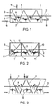
- FIG. 1 shows a schematic side view of a device according to the invention
- FIG. 2 shows a partial view analogous to FIG. 1 with additional partition walls
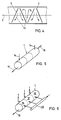
- FIGS. 3 and 4 the flow conditions in the liquid phase in the side view and the top view corresponding to the arrow IV of FIG. 3
- FIG. 5 a perspective view of a multi-chamber training with co-current or counterflow ventilation
- Fig. 6 shows a training with partitions and a cross-flow gas or ventilation.
- a tubular container 1 in which a shaft 2 is rotatably mounted.
- the shaft 2 carries a plurality of disks 3 which, in the side view shown in FIG. 1 and the axial section shown in FIG. 1, alternately enclose an angle of greater and less than 90 ° with the shaft 2. The corresponding angles are alternately the same.
- the disks 3 dip into the liquid level 4 of a liquid 5, the inflow of liquid being controllable via a shut-off valve 6.
- the inner wall of the tubular container is denoted by 7 and the outer circumference of the disks 3, which in the case of a tube with a circular diameter have an essentially round or elliptical outline shape, lies at a short distance from the inner jacket 7 of the tubular container 1.
- partition walls 10 are additionally provided between adjacent chambers, which have overflow openings 11 below the liquid level 4.
- FIG. 3 corresponds to the view according to FIG. 1 and the raising or lowering of the liquid level in adjacent chambers leads to a corresponding flow directed towards the surface and away from the surface, as is illustrated in greater detail by the arrows 12.
- FIG. 4 shows the corresponding top view of the arrangement according to FIG. 2 and the arrows 13 symbolize the resulting cross flows with each revolution of the disks 3.
- the disks 3 are loaded with microorganisms for the biological conversion and have a rough surface for this purpose. Preference is given to disks made of wire mesh or expanded metal, which represent a throttle resistance in the axial direction. With such designs, the raising or lowering of the liquid level in neighboring chambers is of course not pronounced. Based on the flow conditions illustrated in FIGS. 3 and 4, however, there is a flow movement which penetrates the disks 3 in the axial direction, as a result of which the substrate makes intensive contact with the microorganisms.
- FIG. 5 shows a multi-chamber reactor in perspective, the gas inlet or outlet openings being designated by 14.
- the liquid is supplied and discharged via lines 15.
- the gas flow can be obtained in countercurrent in cocurrent or in cocurrent to the direction of flow of the liquid.
- a cross flow is selected, with corresponding partition walls 10, as shown in FIG. 2, being provided between the individual sections 16, 17 and 18 of the tubular container 1.
- These partitions 10 have overflow openings 11 below the liquid level and the gas flow takes place for each of the individual chambers 16, 17 and 18 in each case transversely to the direction of flow of the liquid, which is symbolized by the arrow 19.
- Different or identical gases can be supplied to the individual sections. 6, the gas is supplied via a manifold 20 and thus the same gas to each section.
Landscapes
- Life Sciences & Earth Sciences (AREA)
- Chemical & Material Sciences (AREA)
- Organic Chemistry (AREA)
- Engineering & Computer Science (AREA)
- Health & Medical Sciences (AREA)
- Microbiology (AREA)
- Wood Science & Technology (AREA)
- Bioinformatics & Cheminformatics (AREA)
- Zoology (AREA)
- Biodiversity & Conservation Biology (AREA)
- Hydrology & Water Resources (AREA)
- Environmental & Geological Engineering (AREA)
- Water Supply & Treatment (AREA)
- Biomedical Technology (AREA)
- Genetics & Genomics (AREA)
- Biotechnology (AREA)
- Sustainable Development (AREA)
- Biochemistry (AREA)
- General Engineering & Computer Science (AREA)
- General Health & Medical Sciences (AREA)
- Chemical Kinetics & Catalysis (AREA)
- Molecular Biology (AREA)
- Clinical Laboratory Science (AREA)
- Apparatus Associated With Microorganisms And Enzymes (AREA)
- Biological Treatment Of Waste Water (AREA)
- Degasification And Air Bubble Elimination (AREA)
- Purification Treatments By Anaerobic Or Anaerobic And Aerobic Bacteria Or Animals (AREA)
Description
- Die Erfindung bezieht sich auf eine Einrichtung zum kontinuierlichen Einbringen oder Ausbringen bzw. Adsorption und Desorption von Gasen in oder aus Flüssigkeiten, insbesondere von Substraten in biologischer Umsetzung, mit einem in die Flüssigkeit eintauchenden Rotor, sowie eine Verwendung einer derartigen Einrichtung für aerobe und anaerobe Umsetzungen von Substraten.
- Unter Einbringen bzw. Ausbringen von Gasen in Flüssigkeiten soll im folgenden auch jede kontinuierliche Absorption bzw. Desorption mit oder ohne chemische Umsetzung verstanden werden.
- Für die Belüftung bzw. Begasung von Flüssigkeiten ist es bereits bekannt, eine Reihe von Düsen unterhalb der Flüssigkeitsoberfläche eintauchen zu lassen. Es ist weiters bereits bekannt, für die bessere Durchmischung rotierende Flügelräder vorzusehen.
- Im Zusammenhang mit der biologischen Umsetzung von Substraten ist es beispielsweise aus der DE-A-26 25 230 für die Behandlung von Abwässern bekanntgeworden, Mikroorganismen auf rotierenden Scheiben anzuordnen, welche zyklisch in das umzusetzende Substrat eintauchen und aus diesem Substrat wieder herausgehoben werden. Mit derartigen Einrichtungen wurde bereits der Vorteil erzielt, daß die Mikroorganismen kurzfristig sich unter vom Substrat verschiedenen Bedingungen wieder regenerieren konnten. Auf ähnliche Weise konnte bei Verwendung von Hefe zur Gärung ein Regenerieren der Hefe an sauerstoffhaltigen Gasen zwischengeschaltet werden, bevor die Hefe neuerlich in das zu vergärende Substrat eintauchte.
- Aus der US-A-4 211 647 ist weiters ein anaerobes Verfahren zur Behandlung von Abwässern bekanntgeworden, wobei in einem quadratischen Querschnitt aufweisenden Gehäuse auf eine drehbare Welle normal stehende Scheiben in die zu behandelnde Flüssigkeit eintauchen, wobei an den rotierenden Scheiben wiederum Mikroorganismen anhaften. Die Flüssigkeit wird dabei durch die in einem Gehäuse angeordnete Einrichtung hindurchgepumpt. Aus der FR-A-1 320 157 ist in diesem Zusammenhang ein rotierendes Filter bekanntgeworden, an dessen bürstenförmiger Außenfläche Mikroorganismen anhaften. Aus der FR-A-2 264 584 ist eine Einrichtung zum Belüften von Flüssigkeiten bekanntgeworden, bei welcher an einer drehbaren Welle Scheiben schwenkbar angeordnet sind und die Welle in ein zu behandelnde Flüssigkeit enthaltendes Becken teilweise eingetaucht wird. Nachteilig bei diesen bekannten Ausbildungen ist die Tatsache, daß neben der Antriebsenergie für die Drehbewegung der Scheiben oder Filter jeweils eigene Vorrichtungen zur Umwälzung bzw. Aufrechterhaltung einer Strömung der zu behandelnden Flüssigkeit vorgesehen sein müssen und/oder für eine Bewegung einer Vorrichtung zur Belüftung bei Anordnung in einem Becken zum Überstreichen der gesamten Oberfläche Sorge getragen werden muß.
- Die Erfindung zielt nun darauf ab, eine Einrichtung der eingangs genannten Art zu schaffen, mit welcher mit geringstem Energieaufwand ein wirksamer Stoffaustausch sichergestellt werden kann und andererseits eine Substratbewegung sichergestellt werden kann, welche die jeweilige Biozönose ohne nennenswerte Diffusionswege unmittelbar mit den umzusetzenden Substraten und Nährsubstraten in Verbindung setzen läßt. Zur Lösung dieser Aufgabe besteht die Erfindung im wesentlichen aus einer Einrichtung zum Einbringen oder Ausbringen von Gasen in oder aus Flüssigkeiten, insbesondere von Substraten in biologischer Umsetzung, mit einem in die Flüssigkeit eintauchenden Rotor, bei welcher der Rotor um eine zur Oberfläche der Flüssigkeit im wesentlichen parallele Achse in einem geschlossenen rohrförmigen Behälter rotierbar gelagert ist, der Rotor in Achsrichtung nebeneinander quer zur Achse orientierte, mit dem Rotor drehfest verbundene Scheiben aufweist, die mit Borsten ausgestattet oder aus porösem, insbesondere geschäumtem Material, Drahtgittern, Maschendrahtgewebe oder Streckmetall ausgebildet sind, wobei in Achsrichtung nebeneinander liegende Scheiben in wenigstens einem die Achse enthaltenden Schnitt abwechselnd einen Winkel von größer und kleiner als 90° einschließen, der Umfang der Scheiben in einem, einen Drosselquerschnitt definierenden Abstand vom Innenmantel des Rohres liegt und an das Rohr wenigstens ein Flüssigkeitszulauf, ein Flüssigkeitsablauf sowie wenigstens eine Gaszutrittsöffnung und eine Gasabzugsöffnung angeschlossen sind. Dadurch, daß der Rotor in einem geschlossenen rohrförmigen Behälter rotierbar gelagert ist, läßt sich eine gerichtete Strömung durch das Rohr hindurch aufrechterhalten und es läßt sich eine kontinuierliche Umsetzung mit jeweils frischem Substrat bzw. frischer Biomasse erzielen. Dadurch, daß der Rotor in Achsrichtung nebeneinander quer zur Achse orientierte, mit dem Rotor drehfest verbundene Scheiben aufweist, die mit Borsten ausgestattet oder aus porösem, insbesondere geschäumtem Material, Drahtgittern, Maschendrahtgewebe oder Streckmaterial ausgebildet sind, läßt sich an der Oberfläche dieser Scheiben eine entsprechende Biomasse adsorbieren. Bei einer derartigen Ausbildung der Oberfläche der Scheiben werden bei jeder Umdrehung der Scheiben nennenswerte Substratmengen in Achsrichtung durch die Scheiben hindurchgepreßt und in die Gegenrichtung wiederum zurückgespült, wodurch eine regelmäßige Spülung und Reinigung der Biozönose erfolgt. Gleichzeitig wird immer neues Substrat an die Mikroorganismen herangeführt, wodurch die Umsetzung bedeutend beschleunigt werden kann. Weiters ist vor allen Dingen die Tatsache, daß die Scheiben in Achsrichtung nebeneinanderliegend in wenigstens einem die Achse enthaltenden Schnitt abwechselnd einen Winkel von größer und kleiner als 90° einschließen und der Umfang der Scheiben in einem, einen Drosselquerschnitt definierenden Abstand vom Innenmantel des Rohres liegt, dafür verantwortlich, daß eine pulsierende Bewegung innerhalb des Rohres erzielt wird, bei welcher der Flüssigkeitsspiegel in benachbarten Abschnitten angehoben und abgesenkt werden kann oder aber im Falle von entsprechend angeordneten Überströmöffnungen in den Scheiben eine gerichtete Strömung aufrechterhalten werden kann. Die Maßnahme, die Scheiben quer und unter einem Winkel abweichend von 90° mit der Rotationsachse an einer Rotationsachse rotierbar zu lagern, führt hiebei in besonders wirksamer Weise zu einer charakteristischen Substratbewegung, die durch auf- und abwärtsgerichtete Strömungen sowie Querströmungen innerhalb des Rohres gekennzeichnet ist. Eben diese Strömungen bewirken ein Ansaugen von oberhalb des Flüssigkeitsspiegels angebotenem Gas in die Flüssigkeit und es wird auf besonders schonende Weise und mit geringstem Energieaufwand eine Begasung der Flüssigkeit, insbesondere eine Belüftung, erzielt. Der geschlossene rohrförmige, in Kammern unterteilte Behälter erlaubt in einfacher Weise den gasdichten Abschluß der Einrichtung, so daß verschiedenste Gasatmosphären oberhalb des Flüssigkeitsspiegels eingebracht werden können und durch die Flüssigkeit auf Grund ihrer Bewegung, insbesondere ihrer Oberflächenbewegung, angesaugt werden können. An das Rohr ist hiebei wenigstens ein Flüssigkeitszulauf, ein Flüssigkeitsablauf sowie wenigstens eine Gaszutrittsöffnung und eine Gasabzugsöffnung angeschlossen. Die auf Grund ihrer Orientierung zur Achse eine Trommelbewegung ausübenden Scheiben üben ein gewisses Ausmaß an Schereffekt auf die Flüssigkeit aus, welches gleichfalls unter Ausschluß nennenswerter Diffusionswege eine rasche Umsetzung mit einer an den Scheiben anhaftenden Biozönose sicherstellt.
- Gleichzeitig erlaubt die erfindungsgemäße Ausbildung das abwechselnde Regenerieren von biologischem Material durch Austauchen aus der Flüssigkeit, wobei durch Wahl der entsprechenden Gasatmosphäre eine oxidative Regenerierung, beispielsweise im Falle von Hefen, oder eine Regenerierung unter einer jeweils angepaßten Gasatmosphäre erfolgen kann.
- In benachbarten Bereichen des Behälters läßt sich ohne weiteres alternativ eine aerobe und eine anaerobe Umsetzung durchführen, wofür es beispielsweise genügt, daß der rohrförmige Behälter in Achsrichtung durch im wesentlichen normal zur Achse orientierte Trennwände in Kammern unterteilt ist, welche Drosselquerschnitte für den Materialtransport zwischen benachbarten Kammern aufweisen. Diese Drosselquerschnitte für den Materialtransport zwischen benachbarten Kammern liegen unterhalb der Oberfläche der Flüssigkeit und es wird dadurch ein gasdichter Abschluß erzielt. Es kann somit in benachbarten Abschnitten eine unterschiedliche Gasatmosphäre eingesetzt werden. Der Transport des flüssigen Mediums kann durch externe Pumpen bewerkstelligt werden. Die Scheiben können im wesentlichen runden oder elliptischen Umriß aufweisen. Vorzugsweise ist die Füllstandshöhe in den Kammern zweckmäßig auf 20 - 60 % des lichten Durchmessers des rohrförmigen Behälters begrenzt.
- Die Gaszuführ- und Gasaustrittsöffnungen können in einfacher Weise oberhalb der maximalen Füllstandshöhe nahe den beiden Stirnseiten des rohrförmigen Behälters angeschlossen sein. Je nach Strömungsrichtung der Flüssigkeit kann im Gegenstrom im Gleichstrom oder im Kreuzstrom mit der Flüssigkeit eine Begasung durchgeführt werden. Im Falle der Anordnung von Trennwänden kann die Ausbildung so getroffen sein, daß die Trennwände der einzelnen Kammern ortsfest angeordnet sind und Überströmöffnungen unterhalb der Füllstandshöhe, vorzugsweise im Bereich nahe dem Innenmantel des Behälters, angeordnet sind, und daß an jede Kammer gesonderte, quer zur Rotationsachse angeordnete Gaseintrags- und Gasaustragsöffnungen angeschlossen sind.
- Die Scheiben können mit Mikroorganismen oder Biomasse beschichtet sein, um eine biologische Umsetzung durchzuführen. Biologische Umsetzungen können im Rahmen der Abwasserreinigung in Kläranlagen als anaerobe und aerobe Umsetzungen durchgeführt werden. Im Falle der Faulung von Klärschlamm wird zumeist ein anaerober Prozeß durchgeführt, bei welchem Methan, C02, Klärgas od. dgl. entsteht und aus den jeweiligen Kammern eines derartigen Behälters abgezogen werden kann. Eine Reihe von anaerob umsetzenden Mikroorganismen kann seine Aktivität erheblich erhöhen, wenn zwischenzeitlich eine aerobe Phase eingeschaltet wird, welche durch Austauchen der Bakterien in eine entsprechende Gasatmosphäre oder aber durch Lufteintrag in die Flüssigkeit zumindest in einzelnen Verfahrensstufen bewirkt werden kann. Bei der Essiggärung läuft in der Regel ein aerober Vorgang ab, welcher den Eintrag von Luft erfordert. Bei der kontinuierlichen Alkoholgärung unter Einsatz von mit Zucker angereicherten Hefen verläuft die eigentliche Umsetzung anaerob. Die Effizienz der Hefe kann jedoch wesentlich gesteigert werden, wenn diese zyklisch einer Belüftung unterworfen wird.
- Mit Vorteil kann der Behälter mit Heiz- oder Kühleinrichtungen ausgestattet sein.
- In besonders vorteilhafter Weise wird die erfindungsgemäße Einrichtung zum Belüften von Flüssigkeiten, insbesondere für aerobe Umsetzungen, verwendet. Die Einrichtung kann jedoch ebenso zum kontinuierlichen Gären von Alkohol aus vergärbarem Substrat oder generell für anaerobe Umsetzungen wie Faulung von Klärschlamm od. dgl. eingesetzt werden.
- Weiters kann die erfindungsgemäße Einrichtung zum Ausgasen bei anaeroben Umsetzungen, insbesondere zur Abtrennung von C02, oder zum schonenden Mischen von Substrat und Biomasse verwendet werden.
- Die Erfindung wird nachfolgend an Hand von in der Zeichnung dargestellten Ausführungsbeispielen näher erläutert. In dieser zeigen: Fig. 1 eine schematische Seitenansicht einer erfindungsgemäßen Einrichtung, Fig. 2 eine Teilansicht analog der Fig. 1 mit zusätzlichen Trennwänden, Fig. 3 und 4 die Strömungsverhältnisse in der flüssigen Phase in der Seitenansicht bzw. der Draufsicht entsprechend dem Pfeil IV der Fig. 3, Fig. 5 eine perspektivische Darstellung einer Mehrkammerausbildung mit Gleich- oder Gegenstrombelüftung, und Fig. 6 eine Ausbildung mit Trennwänden und einer Querstrombegasung bzw. -belüftung.
- In Fig. 1 ist ein rohrförmiger Behälter 1 dargestellt, in welchem eine Welle 2 drehbar gelagert ist. Die Welle 2 trägt eine Mehrzahl von Scheiben 3, welche in der in Fig. 1 dargestellten Seitenansicht bzw. dem in Fig. 1 dargestellten Axialschnitt abwechselnd einen Winkel von größer und kleiner als 90° mit der Welle 2 einschließen. Die entsprechenden Winkel sind hiebei abwechselnd entgegengesetzt gleich. Die Scheiben 3 tauchen in den Flüssigkeitsspiegel 4 einer Flüssigkeit 5 ein, wobei der Zulauf von Flüssigkeit über ein Absperrventil 6 regelbar ist. Die Innenwand des rohrförmigen Behälters ist mit 7 bezeichnet und der Außenumfang der Scheiben 3, welche bei einem Rohr mit kreisrundem Durchmesser im wesentlichen runde oder elliptische Umrißform aufweisen, liegt in geringem Abstand vom Innenmantel 7 des rohrförmigen Behälters 1. Bei jeder Umdrehung der Scheiben 3, gemeinsam mit der Welle 2, erfolgt eine abwechselnde Anhebung und Absenkung des Flüssigkeitsspiegels 4, sofern der Drosselquerschnitt der zwischen dem Umfang der Scheiben 3 und der Innenwand 7 des Behälters verbleibt, hinreichend klein ist. Der Abfluß der Flüssigkeit wird über ein Absperrventil 8 geregelt. Die Gasatmosphäre kann je nach den Erfordernissen über ein Ventil 9 zugeführt oder abgeführt werden. Da der Behälter 1 druckfest ausgebildet ist, läßt sich die Anordnung auch unter unteratmosphärischem Druck betreiben.
- Bei der Darstellung nach Fig. 2 sind zusätzlich Trennwände 10 zwischen benachbarten Kammern vorgesehen, welche Überströmöffnungen 11 unterhalb des Flüssigkeitsspiegels 4 aufweisen.
- In Fig. 3 und 4 sind die Strömungsverhältnisse in der flüssigen Phase näher erläutert. Die Fig. 3 entspricht hiebei der Ansicht nach Fig. 1 und die Anhebung bzw. Absenkung des Flüssigkeitsspiegels in benachbarten Kammern führt zu einer entsprechenden zur Oberfläche und von der Oberfläche weg gerichteten Strömung, wie sie durch die Pfeile 12 näher veranschaulicht ist. In Fig. 4 ist die entsprechende Draufsicht auf die Anordnung nach Fig. 2 dargestellt und durch die Pfeile 13 sind die sich ergebenden Querströmungen bei jeder Umdrehung der Scheiben 3 symbolisiert.
- Die Scheiben 3 sind für die biologische Umsetzung mit Mikroorganismen beladen und weisen zu diesem Zweck eine rauhe Oberfläche auf. Bevorzugt sind Scheiben aus Drahtgittern oder -Streckmetall, welche einen Drosselwiderstand in Achsrichtung darstellen. Bei derartigen Ausbildungen ist die Anhebung bzw. Absenkung des Flüssigkeitsspiegels in benachbarten Kammern selbstverständlich nicht ausgeprägt. Auf Grund der in Fig. 3 und 4 veranschaulichten Strömungsverhältnisse erfolgt aber eine in Achsrichtung die Scheiben 3 durchsetzende Strömungsbewegung, wodurch ein intensiver Kontakt des Substrates mit den Mikroorganismen erfolgt.
- In Fig. 5 ist ein Mehrkammerreaktor perspektivisch dargestellt, wobei die Gaseintrags- bzw. -austragsöffnungen mit 14 bezeichnet sind. Die Flüssigkeit wird über Leitungen 15 zu- und abgeführt. Je nach der Zuführungsrichtung des Gases kann die Gasführung im Gegenstrom im Gleichstrom oder im Gleichstrom zur Strömungsrichtung der Flüssigkeit erhalten werden.
- Bei der Ausbildung nach Fig. 6 wird ein Querstrom gewählt, wobei zwischen den einzelnen Abschnitten 16, 17 und 18 des rohrförmigen Behälters 1 entsprechende Trennwände 10, wie in Fig. 2 dargestellt, vorgesehen sind. Diese Trennwände 10 weisen Überströmöffnungen 11 unterhalb des Flüssigkeitsspiegels auf und die Gasströmung erfolgt für jede der einzelnen Kammern 16, 17 und 18 jeweils quer zur Strömungsrichtung der Flüssigkeit, welche durch den Pfeil 19 symbolisiert ist. Den einzelnen Abschnitten können unterschiedliche oder gleiche Gase zugeführt werden. Bei der Darstellung nach Fig. 6 wird das Gas über eine Sammelleitung 20 und damit jedem Abschnitt das gleiche Gas zugeführt.
Claims (9)
Applications Claiming Priority (2)
| Application Number | Priority Date | Filing Date | Title |
|---|---|---|---|
| AT0106785A AT390603B (de) | 1985-04-09 | 1985-04-09 | Einrichtung zum einbringen oder ausbringen von gasen in oder aus fluessigkeiten und verwendung der einrichtung |
| AT1067/85 | 1985-04-09 |
Publications (2)
| Publication Number | Publication Date |
|---|---|
| EP0216872A1 EP0216872A1 (de) | 1987-04-08 |
| EP0216872B1 true EP0216872B1 (de) | 1990-09-19 |
Family
ID=3505887
Family Applications (1)
| Application Number | Title | Priority Date | Filing Date |
|---|---|---|---|
| EP19860902269 Expired - Lifetime EP0216872B1 (de) | 1985-04-09 | 1986-04-09 | Einrichtung zum kontinuierlichen einbringen bzw. ausbringen von gasen in bzw. aus flüssigkeiten |
Country Status (6)
| Country | Link |
|---|---|
| US (1) | US4789469A (de) |
| EP (1) | EP0216872B1 (de) |
| JP (1) | JPS62502597A (de) |
| AT (1) | AT390603B (de) |
| DE (1) | DE3674311D1 (de) |
| WO (1) | WO1986006060A1 (de) |
Families Citing this family (9)
| Publication number | Priority date | Publication date | Assignee | Title |
|---|---|---|---|---|
| US4897195A (en) * | 1989-04-11 | 1990-01-30 | Erickson Stewart E | System and process for anaerobic digestion of waste materials |
| US5366698A (en) * | 1989-12-05 | 1994-11-22 | The University Of Toronto, Innovations Foundation | Apparatus for effecting gas liquid contact |
| US5174973A (en) * | 1989-12-05 | 1992-12-29 | University Of Toronto Innovations Foundation | Method and apparatus for effecting gas-liquid contact |
| US5352421A (en) * | 1989-12-05 | 1994-10-04 | University Of Toronto Innovations Foundation | Method and apparatus for effecting gas-liquid contact |
| US5520818A (en) * | 1989-12-06 | 1996-05-28 | The University Of Toronto Innovations Foundation | Method for effecting gas-liquid contact |
| US5328677A (en) * | 1992-06-17 | 1994-07-12 | Pvl Limited Partnership I | Recovery of sulfides from tannery waste liquor |
| US5500130A (en) * | 1994-11-29 | 1996-03-19 | The University Of Toronto Innovations Foundation And Apollo Environmental Systems Corp. | Method for effecting gas-liquid contact |
| FR2885900B1 (fr) * | 2005-05-20 | 2009-02-13 | Omya Development Ag | Matieres minerales contenant du carbonate a emission en gaz carbonique combustible fossile reduite lors de leurs decompositions ainsi que leur procede de synthese et leurs utilisations. |
| US20070065351A1 (en) * | 2005-09-12 | 2007-03-22 | Kenneth Haggerty | Transfer apparatus and system, and uses thereof |
Family Cites Families (15)
| Publication number | Priority date | Publication date | Assignee | Title |
|---|---|---|---|---|
| US147717A (en) * | 1874-02-17 | Improvement in paper-pulp screens and dressers | ||
| US2740696A (en) * | 1951-03-30 | 1956-04-03 | Exxon Research Engineering Co | Polymerization apparatus unit |
| FR1320157A (fr) * | 1962-01-25 | 1963-03-08 | Filtre à rotor d'oxydation à brosses pour traitement d'eaux résiduaires | |
| AT271357B (de) * | 1967-05-19 | 1969-05-27 | Georg Dipl Ing Dr Tech Gorbach | Verfahren und Vorrichtung zur kontinuierlichen Vergärung |
| DE1784892C3 (de) * | 1968-07-09 | 1975-09-11 | Fritz Dipl.-Ing. 3001 Anderten Engelbart | Vorrichtung zur Abwasserreinigung |
| SE325236B (de) * | 1969-04-22 | 1970-06-22 | Svenska Interpur Ab | |
| US3684458A (en) * | 1970-01-08 | 1972-08-15 | Firestone Tire & Rubber Co | Propulsion and processing apparatus for flowable materials |
| CH584056A5 (de) * | 1971-03-19 | 1977-01-31 | Firestone Tire & Rubber Co | |
| FR2264584A1 (en) * | 1974-03-20 | 1975-10-17 | Schmidt Jean Pierre | Mechanical aerator for biological purifn of polluted effluent - can be adjusted to vary aeration rate without speed change or stopping |
| US4101384A (en) * | 1974-11-16 | 1978-07-18 | Friedrich Uhde Gmbh | Apparatus for the fermentative conversion of a nutrient mixture by means of microorganisms |
| CH592025A5 (de) * | 1975-06-06 | 1977-10-14 | Schneider Martha | |
| US4211647A (en) * | 1979-02-12 | 1980-07-08 | Friedman Alexander A | Anaerobic method of treating high-strength waste-water |
| GB2072647A (en) * | 1979-08-02 | 1981-10-07 | Hancock M C | Biological reactor |
| AT377246B (de) * | 1980-06-10 | 1985-02-25 | Waagner Biro Ag | Tauchtropfkoerper |
| FR2490622A1 (fr) * | 1980-09-22 | 1982-03-26 | Degremont | Aerateur a axe horizontal pour l'epuration des eaux usees |
-
1985
- 1985-04-09 AT AT0106785A patent/AT390603B/de not_active IP Right Cessation
-
1986
- 1986-04-09 EP EP19860902269 patent/EP0216872B1/de not_active Expired - Lifetime
- 1986-04-09 DE DE8686902269T patent/DE3674311D1/de not_active Expired - Fee Related
- 1986-04-09 JP JP61502287A patent/JPS62502597A/ja active Pending
- 1986-04-09 US US07/001,641 patent/US4789469A/en not_active Expired - Fee Related
- 1986-04-09 WO PCT/AT1986/000029 patent/WO1986006060A1/de not_active Ceased
Also Published As
| Publication number | Publication date |
|---|---|
| WO1986006060A1 (fr) | 1986-10-23 |
| JPS62502597A (ja) | 1987-10-08 |
| US4789469A (en) | 1988-12-06 |
| EP0216872A1 (de) | 1987-04-08 |
| DE3674311D1 (de) | 1990-10-25 |
| AT390603B (de) | 1990-06-11 |
| ATA106785A (de) | 1989-11-15 |
Similar Documents
| Publication | Publication Date | Title |
|---|---|---|
| EP0359969A1 (de) | Filter zur Reinigung von Fluiden | |
| DE2303657A1 (de) | Apparat zum zustandebringen einer beruehrung zwischen einer fluessigkeit und einem gas | |
| AT390603B (de) | Einrichtung zum einbringen oder ausbringen von gasen in oder aus fluessigkeiten und verwendung der einrichtung | |
| EP0005553B1 (de) | Vorrichtung zur Umsetzung von in Abwässern und Abwasserschlämmen enthaltenen Stoffen | |
| DE2216917A1 (de) | Verfahren und vorrichtung zum einbringen eines gases in eine fluessigkeit, insbesondere von sauerstoff in wasser | |
| DE102009009579A1 (de) | Vorrichtung und Verfahren zur Beschichtung von Wabenkörpern | |
| DE2738181A1 (de) | Vorrichtung und verfahren zum behandeln einer abfallhaltigen fluessigkeit | |
| DE3503723C2 (de) | ||
| EP0323610B1 (de) | Verfahren und Einrichtung zum Eindicken von Abwasserschlämmen und/oder anderen organischen Schlämmen durch Trennung von Wasser und Feststoffen | |
| DE3900727A1 (de) | Verfahren und vorrichtung zur reinigung von abwasser oder abgasen | |
| DE4120143C1 (en) | Biologically treating organically contaminated liq. - by feeding from pipes at vessel base up through central pipe into chambers contg. many pivoting plates | |
| EP0233924B1 (de) | Nachklärvorrichtung | |
| DE2827996A1 (de) | Vorrichtung zur biologischen reinigung von abwasser | |
| DE3214798C2 (de) | Verfahren und Vorrichtung zur anaeroben Aufbereitung von Abfall | |
| DE2420744B2 (de) | Vorrichtung zum Reinigen von Abwasser | |
| DE19633629A1 (de) | Verfahren und Vorrichtung zur biologischen Abwassserrreinigung | |
| DE2944804A1 (de) | Vorrichtung zum verarbeiten von abwasser | |
| DE2625230A1 (de) | Vorrichtung zur biologischen abwasser-reinigung | |
| DE4240062C1 (de) | Festbettreaktor zur biologischen Behandlung von Abwasser | |
| DE19506183C1 (de) | Verfahren und Vorrichtung zur Nahrungszuführung und Stoffwechselproduktabführung bei der aeroben und anaeroben Fermentation | |
| DE19520564C1 (de) | Verfahren und Vorrichtung zur Denitrifikation in Rotationstauchkörper-Systemen | |
| EP0387241B1 (de) | Verfahren und Vorrichtung zur Begasung von Flüssigkeiten | |
| DE3324072A1 (de) | Vorrichtung zur anaeroben abwasserreinigung | |
| DE2919221A1 (de) | Rotierender hohlspiraltropfkoerper zur chemophysikalisch - biologischen abwasserreinigung | |
| AT216978B (de) | Verfahren und Vorrichtung zur biologischen Abwassereinigung |
Legal Events
| Date | Code | Title | Description |
|---|---|---|---|
| PUAI | Public reference made under article 153(3) epc to a published international application that has entered the european phase |
Free format text: ORIGINAL CODE: 0009012 |
|
| AK | Designated contracting states |
Kind code of ref document: A1 Designated state(s): BE CH DE FR GB IT LI LU NL SE |
|
| 17P | Request for examination filed |
Effective date: 19870407 |
|
| 17Q | First examination report despatched |
Effective date: 19880203 |
|
| GRAA | (expected) grant |
Free format text: ORIGINAL CODE: 0009210 |
|
| AK | Designated contracting states |
Kind code of ref document: B1 Designated state(s): BE CH DE FR GB IT LI LU NL SE |
|
| PG25 | Lapsed in a contracting state [announced via postgrant information from national office to epo] |
Ref country code: IT Free format text: LAPSE BECAUSE OF FAILURE TO SUBMIT A TRANSLATION OF THE DESCRIPTION OR TO PAY THE FEE WITHIN THE PRE;WARNING: LAPSES OF ITALIAN PATENTS WITH EFFECTIVE DATE BEFORE 2007 MAY HAVE OCCURRED AT ANY TIME BEFORE 2007. THE CORRECT EFFECTIVE DATE MAY BE DIFFERENT FROM THE ONE RECORDED.SCRIBED TIME-LIMIT Effective date: 19900919 Ref country code: GB Effective date: 19900919 Ref country code: FR Effective date: 19900919 Ref country code: NL Effective date: 19900919 Ref country code: SE Effective date: 19900919 Ref country code: BE Effective date: 19900919 |
|
| REF | Corresponds to: |
Ref document number: 3674311 Country of ref document: DE Date of ref document: 19901025 |
|
| EN | Fr: translation not filed | ||
| NLV1 | Nl: lapsed or annulled due to failure to fulfill the requirements of art. 29p and 29m of the patents act | ||
| GBV | Gb: ep patent (uk) treated as always having been void in accordance with gb section 77(7)/1977 [no translation filed] | ||
| PG25 | Lapsed in a contracting state [announced via postgrant information from national office to epo] |
Ref country code: LI Effective date: 19910430 Ref country code: LU Free format text: LAPSE BECAUSE OF NON-PAYMENT OF DUE FEES Effective date: 19910430 Ref country code: CH Effective date: 19910430 |
|
| PLBE | No opposition filed within time limit |
Free format text: ORIGINAL CODE: 0009261 |
|
| STAA | Information on the status of an ep patent application or granted ep patent |
Free format text: STATUS: NO OPPOSITION FILED WITHIN TIME LIMIT |
|
| 26N | No opposition filed | ||
| REG | Reference to a national code |
Ref country code: CH Ref legal event code: PL |
|
| PG25 | Lapsed in a contracting state [announced via postgrant information from national office to epo] |
Ref country code: DE Effective date: 19920201 |