EP0216664B1 - Verfahren zur Herstellung von Dischwefeldekafluorid und Schwefelhexafluorid - Google Patents
Verfahren zur Herstellung von Dischwefeldekafluorid und Schwefelhexafluorid Download PDFInfo
- Publication number
- EP0216664B1 EP0216664B1 EP19860401829 EP86401829A EP0216664B1 EP 0216664 B1 EP0216664 B1 EP 0216664B1 EP 19860401829 EP19860401829 EP 19860401829 EP 86401829 A EP86401829 A EP 86401829A EP 0216664 B1 EP0216664 B1 EP 0216664B1
- Authority
- EP
- European Patent Office
- Prior art keywords
- process according
- sulphur
- hexafluoride
- wavelength
- reaction
- Prior art date
- Legal status (The legal status is an assumption and is not a legal conclusion. Google has not performed a legal analysis and makes no representation as to the accuracy of the status listed.)
- Expired - Lifetime
Links
- 238000000034 method Methods 0.000 title claims description 50
- 230000008569 process Effects 0.000 title claims description 41
- SFZCNBIFKDRMGX-UHFFFAOYSA-N sulfur hexafluoride Chemical compound FS(F)(F)(F)(F)F SFZCNBIFKDRMGX-UHFFFAOYSA-N 0.000 title claims description 28
- 229960000909 sulfur hexafluoride Drugs 0.000 title claims description 24
- BPFZRKQDXVZTFD-UHFFFAOYSA-N disulfur decafluoride Chemical compound FS(F)(F)(F)(F)S(F)(F)(F)(F)F BPFZRKQDXVZTFD-UHFFFAOYSA-N 0.000 title claims description 8
- 229910018503 SF6 Inorganic materials 0.000 title description 21
- 238000004519 manufacturing process Methods 0.000 title description 20
- 239000007789 gas Substances 0.000 claims description 81
- 238000006243 chemical reaction Methods 0.000 claims description 66
- SANRKQGLYCLAFE-UHFFFAOYSA-H uranium hexafluoride Chemical compound F[U](F)(F)(F)(F)F SANRKQGLYCLAFE-UHFFFAOYSA-H 0.000 claims description 57
- 239000000203 mixture Substances 0.000 claims description 45
- 230000005855 radiation Effects 0.000 claims description 38
- QHMQWEPBXSHHLH-UHFFFAOYSA-N sulfur tetrafluoride Chemical compound FS(F)(F)F QHMQWEPBXSHHLH-UHFFFAOYSA-N 0.000 claims description 34
- 230000036961 partial effect Effects 0.000 claims description 29
- NINIDFKCEFEMDL-UHFFFAOYSA-N Sulfur Chemical compound [S] NINIDFKCEFEMDL-UHFFFAOYSA-N 0.000 claims description 19
- 239000007787 solid Substances 0.000 claims description 19
- 239000008246 gaseous mixture Substances 0.000 claims description 18
- 239000012265 solid product Substances 0.000 claims description 17
- IJGRMHOSHXDMSA-UHFFFAOYSA-N Atomic nitrogen Chemical compound N#N IJGRMHOSHXDMSA-UHFFFAOYSA-N 0.000 claims description 14
- 238000002360 preparation method Methods 0.000 claims description 14
- 238000007323 disproportionation reaction Methods 0.000 claims description 13
- 239000012535 impurity Substances 0.000 claims description 12
- 238000010438 heat treatment Methods 0.000 claims description 11
- XKRFYHLGVUSROY-UHFFFAOYSA-N Argon Chemical compound [Ar] XKRFYHLGVUSROY-UHFFFAOYSA-N 0.000 claims description 10
- 230000004907 flux Effects 0.000 claims description 9
- 238000000746 purification Methods 0.000 claims description 8
- 229910052757 nitrogen Inorganic materials 0.000 claims description 7
- QTJXVIKNLHZIKL-UHFFFAOYSA-N sulfur difluoride Chemical class FSF QTJXVIKNLHZIKL-UHFFFAOYSA-N 0.000 claims description 7
- 230000005284 excitation Effects 0.000 claims description 6
- JNVYCANIFQDNST-UHFFFAOYSA-I uranium pentafluoride Chemical group [F-].[F-].[F-].[F-].[F-].[U+5] JNVYCANIFQDNST-UHFFFAOYSA-I 0.000 claims description 6
- 229910052786 argon Inorganic materials 0.000 claims description 5
- LSJNBGSOIVSBBR-UHFFFAOYSA-N thionyl fluoride Chemical compound FS(F)=O LSJNBGSOIVSBBR-UHFFFAOYSA-N 0.000 claims description 5
- 238000011282 treatment Methods 0.000 claims description 4
- 239000011541 reaction mixture Substances 0.000 claims description 3
- 229910052734 helium Inorganic materials 0.000 claims description 2
- 239000001307 helium Substances 0.000 claims description 2
- SWQJXJOGLNCZEY-UHFFFAOYSA-N helium atom Chemical compound [He] SWQJXJOGLNCZEY-UHFFFAOYSA-N 0.000 claims description 2
- 238000010408 sweeping Methods 0.000 claims description 2
- 239000005864 Sulphur Substances 0.000 claims 6
- 229910018485 SF4 Inorganic materials 0.000 claims 1
- 150000003671 uranium compounds Chemical class 0.000 claims 1
- 238000009434 installation Methods 0.000 description 22
- 238000010521 absorption reaction Methods 0.000 description 18
- 230000009102 absorption Effects 0.000 description 16
- PXHVJJICTQNCMI-UHFFFAOYSA-N Nickel Chemical compound [Ni] PXHVJJICTQNCMI-UHFFFAOYSA-N 0.000 description 14
- 229910052717 sulfur Inorganic materials 0.000 description 14
- 239000012071 phase Substances 0.000 description 13
- 238000006552 photochemical reaction Methods 0.000 description 13
- 239000011593 sulfur Substances 0.000 description 13
- 238000012360 testing method Methods 0.000 description 12
- 238000010494 dissociation reaction Methods 0.000 description 11
- 230000005593 dissociations Effects 0.000 description 10
- YCKRFDGAMUMZLT-UHFFFAOYSA-N Fluorine atom Chemical compound [F] YCKRFDGAMUMZLT-UHFFFAOYSA-N 0.000 description 9
- 230000015572 biosynthetic process Effects 0.000 description 9
- 229910052731 fluorine Inorganic materials 0.000 description 9
- 239000000047 product Substances 0.000 description 9
- 150000001875 compounds Chemical class 0.000 description 8
- 239000011737 fluorine Substances 0.000 description 8
- 239000002245 particle Substances 0.000 description 8
- 230000007797 corrosion Effects 0.000 description 7
- 238000005260 corrosion Methods 0.000 description 7
- 230000007935 neutral effect Effects 0.000 description 7
- 229910052759 nickel Inorganic materials 0.000 description 7
- 239000000376 reactant Substances 0.000 description 7
- 238000000926 separation method Methods 0.000 description 7
- 238000003786 synthesis reaction Methods 0.000 description 7
- 229910052770 Uranium Inorganic materials 0.000 description 6
- 239000003153 chemical reaction reagent Substances 0.000 description 6
- 230000003287 optical effect Effects 0.000 description 6
- 238000006303 photolysis reaction Methods 0.000 description 6
- 239000000126 substance Substances 0.000 description 6
- JFALSRSLKYAFGM-UHFFFAOYSA-N uranium(0) Chemical compound [U] JFALSRSLKYAFGM-UHFFFAOYSA-N 0.000 description 6
- 125000001153 fluoro group Chemical group F* 0.000 description 5
- VSQYNPJPULBZKU-UHFFFAOYSA-N mercury xenon Chemical compound [Xe].[Hg] VSQYNPJPULBZKU-UHFFFAOYSA-N 0.000 description 5
- 229920000642 polymer Polymers 0.000 description 5
- 230000009467 reduction Effects 0.000 description 5
- 230000009471 action Effects 0.000 description 4
- 238000009833 condensation Methods 0.000 description 4
- 230000005494 condensation Effects 0.000 description 4
- 239000000470 constituent Substances 0.000 description 4
- 238000010586 diagram Methods 0.000 description 4
- 239000012025 fluorinating agent Substances 0.000 description 4
- 238000000197 pyrolysis Methods 0.000 description 4
- 239000007790 solid phase Substances 0.000 description 4
- 229910004261 CaF 2 Inorganic materials 0.000 description 3
- KRHYYFGTRYWZRS-UHFFFAOYSA-M Fluoride anion Chemical compound [F-] KRHYYFGTRYWZRS-UHFFFAOYSA-M 0.000 description 3
- 239000000443 aerosol Substances 0.000 description 3
- 239000003638 chemical reducing agent Substances 0.000 description 3
- 238000002474 experimental method Methods 0.000 description 3
- 238000003682 fluorination reaction Methods 0.000 description 3
- 150000002222 fluorine compounds Chemical class 0.000 description 3
- QSHDDOUJBYECFT-UHFFFAOYSA-N mercury Chemical compound [Hg] QSHDDOUJBYECFT-UHFFFAOYSA-N 0.000 description 3
- 229910052751 metal Inorganic materials 0.000 description 3
- 239000002184 metal Substances 0.000 description 3
- 238000006862 quantum yield reaction Methods 0.000 description 3
- XLYOFNOQVPJJNP-UHFFFAOYSA-N water Chemical compound O XLYOFNOQVPJJNP-UHFFFAOYSA-N 0.000 description 3
- KRHYYFGTRYWZRS-UHFFFAOYSA-N Fluorane Chemical compound F KRHYYFGTRYWZRS-UHFFFAOYSA-N 0.000 description 2
- 229910000792 Monel Inorganic materials 0.000 description 2
- -1 U 2 F 9 and UF 4 Chemical class 0.000 description 2
- 230000008901 benefit Effects 0.000 description 2
- 239000007795 chemical reaction product Substances 0.000 description 2
- 230000007423 decrease Effects 0.000 description 2
- 238000000151 deposition Methods 0.000 description 2
- MXCPYJZDGPQDRA-UHFFFAOYSA-N dialuminum;2-acetyloxybenzoic acid;oxygen(2-) Chemical compound [O-2].[O-2].[O-2].[Al+3].[Al+3].CC(=O)OC1=CC=CC=C1C(O)=O MXCPYJZDGPQDRA-UHFFFAOYSA-N 0.000 description 2
- 238000009792 diffusion process Methods 0.000 description 2
- KCKICANVXIVOLK-UHFFFAOYSA-L dioxouranium(2+);difluoride Chemical compound [F-].[F-].O=[U+2]=O KCKICANVXIVOLK-UHFFFAOYSA-L 0.000 description 2
- 230000008034 disappearance Effects 0.000 description 2
- 238000009826 distribution Methods 0.000 description 2
- 230000000694 effects Effects 0.000 description 2
- 238000000605 extraction Methods 0.000 description 2
- 230000002349 favourable effect Effects 0.000 description 2
- 238000004817 gas chromatography Methods 0.000 description 2
- 230000007062 hydrolysis Effects 0.000 description 2
- 238000006460 hydrolysis reaction Methods 0.000 description 2
- PQXKHYXIUOZZFA-UHFFFAOYSA-M lithium fluoride Chemical compound [Li+].[F-] PQXKHYXIUOZZFA-UHFFFAOYSA-M 0.000 description 2
- 238000010926 purge Methods 0.000 description 2
- 238000003303 reheating Methods 0.000 description 2
- 230000002441 reversible effect Effects 0.000 description 2
- 238000001228 spectrum Methods 0.000 description 2
- 238000002211 ultraviolet spectrum Methods 0.000 description 2
- RYGMFSIKBFXOCR-UHFFFAOYSA-N Copper Chemical compound [Cu] RYGMFSIKBFXOCR-UHFFFAOYSA-N 0.000 description 1
- 229910000990 Ni alloy Inorganic materials 0.000 description 1
- 229910052774 Proactinium Inorganic materials 0.000 description 1
- 229910018287 SbF 5 Inorganic materials 0.000 description 1
- 206010039509 Scab Diseases 0.000 description 1
- 239000005935 Sulfuryl fluoride Substances 0.000 description 1
- 150000001224 Uranium Chemical class 0.000 description 1
- 239000002253 acid Substances 0.000 description 1
- 230000004913 activation Effects 0.000 description 1
- 239000003463 adsorbent Substances 0.000 description 1
- 239000012670 alkaline solution Substances 0.000 description 1
- PNEYBMLMFCGWSK-UHFFFAOYSA-N aluminium oxide Inorganic materials [O-2].[O-2].[O-2].[Al+3].[Al+3] PNEYBMLMFCGWSK-UHFFFAOYSA-N 0.000 description 1
- 125000004429 atom Chemical group 0.000 description 1
- QVGXLLKOCUKJST-UHFFFAOYSA-N atomic oxygen Chemical compound [O] QVGXLLKOCUKJST-UHFFFAOYSA-N 0.000 description 1
- OYLGJCQECKOTOL-UHFFFAOYSA-L barium fluoride Chemical compound [F-].[F-].[Ba+2] OYLGJCQECKOTOL-UHFFFAOYSA-L 0.000 description 1
- 229910001632 barium fluoride Inorganic materials 0.000 description 1
- WUKWITHWXAAZEY-UHFFFAOYSA-L calcium difluoride Chemical compound [F-].[F-].[Ca+2] WUKWITHWXAAZEY-UHFFFAOYSA-L 0.000 description 1
- 229910001634 calcium fluoride Inorganic materials 0.000 description 1
- 229910052799 carbon Inorganic materials 0.000 description 1
- 238000005345 coagulation Methods 0.000 description 1
- 230000015271 coagulation Effects 0.000 description 1
- 238000004891 communication Methods 0.000 description 1
- 230000006835 compression Effects 0.000 description 1
- 238000007906 compression Methods 0.000 description 1
- 229910052802 copper Inorganic materials 0.000 description 1
- 239000010949 copper Substances 0.000 description 1
- 238000005336 cracking Methods 0.000 description 1
- 239000013078 crystal Substances 0.000 description 1
- 238000002425 crystallisation Methods 0.000 description 1
- 230000008025 crystallization Effects 0.000 description 1
- 230000007547 defect Effects 0.000 description 1
- 230000008021 deposition Effects 0.000 description 1
- 239000002274 desiccant Substances 0.000 description 1
- 230000001066 destructive effect Effects 0.000 description 1
- 238000011161 development Methods 0.000 description 1
- 208000018459 dissociative disease Diseases 0.000 description 1
- 238000002265 electronic spectrum Methods 0.000 description 1
- 230000005281 excited state Effects 0.000 description 1
- 230000007717 exclusion Effects 0.000 description 1
- 238000001914 filtration Methods 0.000 description 1
- 239000005383 fluoride glass Substances 0.000 description 1
- 229910052736 halogen Inorganic materials 0.000 description 1
- 150000002367 halogens Chemical class 0.000 description 1
- 239000008240 homogeneous mixture Substances 0.000 description 1
- 239000001257 hydrogen Substances 0.000 description 1
- 229910052739 hydrogen Inorganic materials 0.000 description 1
- 125000004435 hydrogen atom Chemical class [H]* 0.000 description 1
- 238000011065 in-situ storage Methods 0.000 description 1
- 238000009776 industrial production Methods 0.000 description 1
- 239000011261 inert gas Substances 0.000 description 1
- 238000005372 isotope separation Methods 0.000 description 1
- 239000007788 liquid Substances 0.000 description 1
- ORUIBWPALBXDOA-UHFFFAOYSA-L magnesium fluoride Chemical compound [F-].[F-].[Mg+2] ORUIBWPALBXDOA-UHFFFAOYSA-L 0.000 description 1
- 229910001635 magnesium fluoride Inorganic materials 0.000 description 1
- 239000000463 material Substances 0.000 description 1
- 229910052753 mercury Inorganic materials 0.000 description 1
- 238000002156 mixing Methods 0.000 description 1
- 239000000178 monomer Substances 0.000 description 1
- 230000003647 oxidation Effects 0.000 description 1
- 238000007254 oxidation reaction Methods 0.000 description 1
- 239000001301 oxygen Substances 0.000 description 1
- 229910052760 oxygen Inorganic materials 0.000 description 1
- 230000003071 parasitic effect Effects 0.000 description 1
- 230000035515 penetration Effects 0.000 description 1
- 230000015843 photosynthesis, light reaction Effects 0.000 description 1
- 239000000843 powder Substances 0.000 description 1
- 238000005086 pumping Methods 0.000 description 1
- 238000011403 purification operation Methods 0.000 description 1
- 230000009257 reactivity Effects 0.000 description 1
- 230000006798 recombination Effects 0.000 description 1
- 238000005215 recombination Methods 0.000 description 1
- 238000001953 recrystallisation Methods 0.000 description 1
- 238000004064 recycling Methods 0.000 description 1
- 238000010992 reflux Methods 0.000 description 1
- 230000000717 retained effect Effects 0.000 description 1
- 238000007789 sealing Methods 0.000 description 1
- 230000035939 shock Effects 0.000 description 1
- 238000001179 sorption measurement Methods 0.000 description 1
- 230000003595 spectral effect Effects 0.000 description 1
- 238000003860 storage Methods 0.000 description 1
- OBTWBSRJZRCYQV-UHFFFAOYSA-N sulfuryl difluoride Chemical compound FS(F)(=O)=O OBTWBSRJZRCYQV-UHFFFAOYSA-N 0.000 description 1
- 239000000725 suspension Substances 0.000 description 1
- 230000009466 transformation Effects 0.000 description 1
- 238000013519 translation Methods 0.000 description 1
- MZFRHHGRNOIMLW-UHFFFAOYSA-J uranium(4+);tetrafluoride Chemical compound F[U](F)(F)F MZFRHHGRNOIMLW-UHFFFAOYSA-J 0.000 description 1
- 238000002460 vibrational spectroscopy Methods 0.000 description 1
Images


Classifications
-
- C—CHEMISTRY; METALLURGY
- C01—INORGANIC CHEMISTRY
- C01B—NON-METALLIC ELEMENTS; COMPOUNDS THEREOF; METALLOIDS OR COMPOUNDS THEREOF NOT COVERED BY SUBCLASS C01C
- C01B17/00—Sulfur; Compounds thereof
- C01B17/45—Compounds containing sulfur and halogen, with or without oxygen
- C01B17/4507—Compounds containing sulfur and halogen, with or without oxygen containing sulfur and halogen only
- C01B17/4515—Compounds containing sulfur and halogen, with or without oxygen containing sulfur and halogen only containing sulfur and fluorine only
- C01B17/453—Sulfur hexafluoride
-
- B—PERFORMING OPERATIONS; TRANSPORTING
- B01—PHYSICAL OR CHEMICAL PROCESSES OR APPARATUS IN GENERAL
- B01J—CHEMICAL OR PHYSICAL PROCESSES, e.g. CATALYSIS OR COLLOID CHEMISTRY; THEIR RELEVANT APPARATUS
- B01J19/00—Chemical, physical or physico-chemical processes in general; Their relevant apparatus
- B01J19/08—Processes employing the direct application of electric or wave energy, or particle radiation; Apparatus therefor
- B01J19/12—Processes employing the direct application of electric or wave energy, or particle radiation; Apparatus therefor employing electromagnetic waves
- B01J19/121—Coherent waves, e.g. laser beams
-
- B—PERFORMING OPERATIONS; TRANSPORTING
- B01—PHYSICAL OR CHEMICAL PROCESSES OR APPARATUS IN GENERAL
- B01J—CHEMICAL OR PHYSICAL PROCESSES, e.g. CATALYSIS OR COLLOID CHEMISTRY; THEIR RELEVANT APPARATUS
- B01J19/00—Chemical, physical or physico-chemical processes in general; Their relevant apparatus
- B01J19/08—Processes employing the direct application of electric or wave energy, or particle radiation; Apparatus therefor
- B01J19/12—Processes employing the direct application of electric or wave energy, or particle radiation; Apparatus therefor employing electromagnetic waves
- B01J19/122—Incoherent waves
- B01J19/123—Ultraviolet light
-
- C—CHEMISTRY; METALLURGY
- C01—INORGANIC CHEMISTRY
- C01B—NON-METALLIC ELEMENTS; COMPOUNDS THEREOF; METALLOIDS OR COMPOUNDS THEREOF NOT COVERED BY SUBCLASS C01C
- C01B17/00—Sulfur; Compounds thereof
- C01B17/45—Compounds containing sulfur and halogen, with or without oxygen
- C01B17/4507—Compounds containing sulfur and halogen, with or without oxygen containing sulfur and halogen only
- C01B17/4515—Compounds containing sulfur and halogen, with or without oxygen containing sulfur and halogen only containing sulfur and fluorine only
-
- C—CHEMISTRY; METALLURGY
- C01—INORGANIC CHEMISTRY
- C01G—COMPOUNDS CONTAINING METALS NOT COVERED BY SUBCLASSES C01D OR C01F
- C01G43/00—Compounds of uranium
- C01G43/04—Halides of uranium
- C01G43/06—Fluorides
Definitions
- the subject of the present invention is a process for the preparation of sulfur fluorides of formula SF 6 and S 2 Fio, as well as uranium pentafluoride UF 5 .
- sulfur hexafluoride is a compound much in demand in the electronics and electrotechnical industry because of its dielectric properties. It is in fact widely used as an insulating medium in electrostatic machines.
- sulfur hexafluoride was discovered by H. MOISSAN and S. LEBEAU in 1900 and you are generally prepared by burning sulfur in the gaseous fluorine.
- sulfur hexafluoride can be obtained by other methods, in particular from sulfur tetrafluoride by reaction of the latter with a fluorinating agent such as uranium hexafluoride. This method of preparing sulfur hexafluoride may be advantageous to exploit commercially since uranium hexafluoride depleted in 235U originating from isotopic separation plants is a cheap source of fluorine atoms.
- This phenomenon is maximum around 650 ° C, the temperature at which recrystallization of nickel begins. Mass attack of the metal at this temperature is acceptable (corrosion of 1 mm / year) but the risk of corrosive cracking beyond 500 ° C absolutely prohibits the use of nickel in this temperature zone. Above 800 ° C, corrosion occurs at the surface at a rate of approximately 2 mm / year. Nickel alloys such as Monel @ exhibit the same effects of intergranular corrosion. Also, the development of a thermal reaction between uranium hexafluoride and sulfur tetrafluoride at temperatures above 450-500 ° C for which the kinetics are still slow, seems difficult to conceive of for industrial production.
- this drawback can be overcome and use lower temperatures, for example of the order of 300 ° C., provided that the light molecules activate the uranium hexafluoride molecules by using light sources which can be absorbed by uranium hexafluoride, for example from sources in the wavelength range of 5 to 6 ⁇ m.
- This can be achieved using a CO laser as described in British Patent GB-A-1,496,125.
- the energy provided by multiphotonic excitation in the low absorption bands of the 5-6 ⁇ m region is insufficient to carry out the dissociation reaction of uranium hexafluoride into uranium pentafluoride and fluorine.
- the present invention specifically relates to a process for the preparation of sulfur fluorides chosen from sulfur hexafluoride SF 6 and sulfur decafluoride S 2 F i o, which overcomes the drawbacks of the above-mentioned processes.
- the process according to the invention for the preparation of sulfur fluorides of formula SF 6 and S 2 F 10 by reaction of sulfur tetrafluoride with uranium hexafluoride is characterized in that a gaseous mixture containing uranium hexafluoride and sulfur tetrafluoride to irradiation by means of ultraviolet radiation having a wavelength of 200 to 400 nm, and in that the decaffluoride and sulfur hexafluoride formed are separated from the reaction mixture.
- a photochemical reaction is carried out between sulfur tetrafluoride and uranium hexafluoride excited by ultraviolet light.
- uranium hexafluoride UF 6 absorbs throughout the ultraviolet as shown by its electronic spectrum in the gas phase shown in Figure 1 which illustrates the cross section (in cm 2 ) of ultraviolet absorption of hexafluoride d 'uranium at 25 ° C as a function of the wavelength ⁇ (in nm). In the wavelength range from 200 to 400 nm, a primary photodissociation of uranium hexafluoride occurs by breaking the UF bond according to the following reaction schemes:
- hy represents the energy of the photons, h being the Planck constant and y the frequency of the radiation used which is equal to c / ⁇ with c representing the speed of light in a vacuum; the notation "*" indicates excited states of all kinds, which may include a combination of electronic, vibrational, rotational and translational excitations existing to a greater degree than in a thermal distribution at room temperature.
- the letter g indicates the gaseous state.
- the dissociation energy F 5 UF being of the order of 3 eV, irradiation in the region of 250 nm where UF 6 has a large cross section as can be seen in FIG.
- the oxidation of sulfur tetrafluoride can be carried out up to the maximum valence VI under ultraviolet light in the spectral region of 200 to 400 nm, by means of UF 6 which is reduced to valence V, according to the overall reaction:
- the present invention also aims to prepare a solid uranium fluoride such as uranium pentafluoride UFs by reduction in the gas phase of UF 6 in the presence of SF 4 .
- the reaction which consists in dissociating UF 6 in the presence of ultraviolet light makes it possible to produce pure UF 5 but it is quickly stopped by the presence of fluorine.
- the present invention overcomes these drawbacks and makes it possible to produce high purity stoichiometric UF 5 .
- the SF 4 used is chosen to be both a reducing agent and a fluorinating gas whose action will be preferable to that of UF 6 with respect to the impurities which will in this way be transformed into gaseous compounds by opposition solid uranium derivatives.
- the gaseous reaction mixture in the presence of steam-water leads to thionyl-gaseous fluoride-SOF 2 and not to the solid UO 2 F 2 , which can on the contrary be regenerated into UF 6 at 300 ° by the reagent SF 4 .
- uranium hexafluoride leaving gas diffusion plants does not contain gaseous impurities capable of being transformed by chemical or photochemical reaction into solid products in the photochemical reaction. proposed in the presence of SF 4 .
- the products of photoreaction SF 6 and S 2 Fio are compounds of high vapor pressures, easily extractable which do not bring sulfur pollution on the compounds of uranium fluorides.
- SF 4 which is one of the reagents, has a maximum absorption at 240 nm with an effective cross-section of 10-19 cm 2, which is 20 times less than that of UF 6 at the same frequency; at 270 nm the difference is increased to 100 in favor of UF 6 .
- the S 2 F 2 which may be present next to the SF 4 has an effective cross-section close to that of the SF 4 , and which remains less than 10-19 cm 2 between 220 and 300 nm.
- SF 6 it is well known that it shows no significant UV absorption cross-section above 125 nm, the first observable absorptions arriving in the 112-100 nm region.
- the relative amounts of SF 6 and S 2 Fio formed by the photochemical reaction depend in particular on the respective local concentrations of SF 4 and UF * 6 represented in the following by [SF 4] and [UF * 6 ].
- the kinetics of disappearance of SF 4 is of order 2 compared to UFS.
- the concentration of SF 4 is proportional to the partial pressure of SF 4 and is written: where T is the absolute temperature and k is the Boltzmann constant.
- the concentration of UF * 6 is proportional to the partial pressure of UF 6 in the gas mixture and to the number of photons of hy energy delivered by the source.
- the partial pressure of UF 6 of the gas mixture is also adjusted to an appropriate value in order to obtain good absorption of the photons and a good yield from the reaction for converting sulfur tetrafluoride into sulfur hexafluoride.
- the partial pressure of UF 6 is 100 to 10,000 Pa and preferably a partial pressure in UF 6 high because the reaction yield increases with the partial pressure in UF 6 .
- the amount of SF 6 produced relative to the amount of SF 4 present at the start of the reaction increases from a few% to 50% when the partial pressure of UF 6 increases. from 100 to 6000 Pa.
- the amount of sulfur hexafluoride produced compared to the amount of sulfur tetrafluoride present in the mixture increases from 10 to 60% when the partial pressure of UF 6 increases from 300 Pa to 9000 Pa.
- the gas mixture can also comprise an inert gas such as nitrogen or argon.
- any source of ultraviolet radiation emitting in the range of wavelengths ranging from 200 to 400 nm can be used.
- the extended ultraviolet sources emitting mainly in the region of short wavelengths, xenon-mercury or mercury arc lamps, continuous or pulsed laser sources, such as laser YAG: Nd3 + with quadrupling of the frequency, or the KrF excimer laser.
- sources emitting in the wavelength range from 200 to 340 nm are used in which the absorption of photons by uranium hexafluoride is greater, as shown in FIG. 1. Therefore, the excited uranium hexafluoride dissociates spontaneously, which makes it possible to obtain a reaction quantum yield reaching the value of 1. It is specified that this yield corresponds to the number of radicals formed by photon hy absorbed by UF 6 .
- the excited uranium hexafluoride dissociates only collidedly and the quantum yield is less than 1.
- the irradiation is then carried out during pulses of a few ns which are very brief compared to the collision time between the excited species and the SF 4 .
- the overall photonic yield of the reaction also depends on the geometry of the enclosure containing the gaseous mixture subjected to irradiation and also on the level of solid UFs particles present in the irradiated mixture. It is specified that the overall photonic reaction yield corresponds to the number of SF 5 radicals formed per photon which enters the reactor (yield ⁇ 1).
- this process for preparing SF 6 and S 2 Fio by reaction of SF 4 on UF 6 electronically excited by UV photons is independent of the internal energy of UF 6 , and therefore of its temperature.
- the reactions described are conveniently carried out at room temperature, but keep the same efficiency if they are carried out at different temperatures, the efficiency being judged from the reaction quantum yield already defined.
- a mixture of UF 6 and SF 4 in the presence of a neutral gas such as nitrogen, argon or helium is cooled by a supersonic expansion in a nozzle at a temperature of 80 to 120 K.
- the SF 4 / UF 6 molar ratio is taken to be greater than 1, which directs the reaction towards the production of S 2 Fio.
- the overall reaction photon yield is less good than it is at room temperature, all conditions being equal, because of a lower absorptivity of UV photons This reduction in a is evaluated at 30% at 250 nm
- the vibrational energy of the UF 6 is increased , either by heating the gas mixture in the enclosure, or by bringing IR or UF 6 photons as for example in the region of 16 ⁇ m, as a result of an increase from the cross section in the region of 220 to 340 nm, UV photons are absorbed more quickly than at room temperature.
- the IR excitation at 16 ⁇ m is carried out with fluences such that they do not cause direct photodissociation of UF 6 .
- the IR excitation (s) will be carried out by pulsed lasers; in this case the UV dissociation of UF ⁇ will also be carried out by a laser. It is specified that the increase in the value of a between 30 ° C and 300 ° C remains less than 20% over the 200-270 nm region of high absorptivity.
- the method of the invention is implemented so as to continuously prepare sulfur hexafluoride or sulfur decafluoride.
- a gaseous mixture comprising sulfur tetrafluoride and uranium hexafluoride is put into circulation in a sealed enclosure, the gaseous mixture circulating in the enclosure is subjected to irradiation by means of ultraviolet radiation and of the gaseous mixture leaving the enclosure the solid products formed during the reaction.
- a gas mixture is thus recovered which contains sulfur hexafluoride, sulfur decafluoride S 2 Fio as well as unreacted SF 4 and UF 6 .
- the gaseous mixture thus recovered is subjected to a heat treatment enabling the S 2 Fio it contains to be transformed into SF 6 , this can be obtained by wearing the gaseous medium leaving the enclosure at a temperature of 150 to 300 ° C for a sufficient time to obtain the disproportionation of S 2 F l o in SF 4 and SF 6 according to the following reaction scheme:
- gaseous mixture leaving the enclosure also contains gaseous fluorine produced according to the reaction (4) described above, this will react easily during the heat treatment with the SF 4 produced by the disproportionation reaction to give SF 6 .
- S 2 Fio constitutes a source of radicals it is enough for that to heat it moderately between 130 and 150 ° C to have the rupture of the connection SS according to the reaction: disproportionation into SF 4 and SF 6 arriving at higher temperatures, as described by MD VOROB'EV, AS FILATOV, MA ENGLIN in J. Gen. Chem. of the USSR 44 2677 (1974).
- the reactions are directed towards the production of SF 6 by producing in the cell where the gas mixture is irradiated SF radicals from the molecules of S 2 Fio produced in the reaction chamber. This can be obtained by heating the enclosure to a temperature of 130 to 400 ° C to obtain the reaction (17).
- the radicals are produced in the enclosure by further subjecting the gas mixture circulating in the enclosure to irradiation by means of infrared radiation having a wavelength of 10 to 12 ⁇ m.
- a continuous C0 2 laser can be used, the yield of which is particularly good in this region. It should be noted that the energy flow at 10 ⁇ m has no action on uranium hexafluoride which does not absorb this frequency, the photons of 1000 cm -1 of energy having little weight vis-à-vis energies necessary to ensure the dissociation of UF 6 , that is to say approximately 25000 cm- 1 .
- the solid phase comprises, in addition to UF 5 , U 2 F 9 in agreement with the relationship.
- the solid product additionally includes the variety UF 4 . If in addition the partial pressure at the end of the photochemical reaction is limited to 1000 Pa for the reactor at 400 ° C., the following overall reaction is observed: uranium fluoride UF 4, stoichiometric, pure, thus obtained from a disproportionation in the gas phase of U 2 F 9 according to the relationship:
- the density of will be voluntarily limited to 10 14 cm- 3 to limit the size of uranium fluorides UF S and of intermediate valence between 4 and 5 to a few tens of nanometers.
- the gas UF 6 can be reduced to a solid UF 4 at room temperature directly after absorption of two UV photons of identical or different wavelengths but between 200 and 340 nm according to the diagram:
- the UF 6 gas can also be reduced to the UF 4 state by passing through an intermediate stage such as UFS, which is achieved by absorption of two photons, one of which is a UV photon with a wavelength between 200 and 340 nm, and the other a UV visible photon with a wavelength between 200 and 500 nm according to the diagram:
- this photochemistry between SF 4 and UF 6 electronically excited is not limited by the total pressure of the reagents present.
- the limitation comes from the possibility for the light source to supply photons in energy and sufficient number to dissociate UF 6 .
- the UF 6 gas can always be introduced into the reactor at a concentration sufficient for the photons of energy between 200 and 340 nm to be absorbed, that is to say for the product a ( ⁇ ) [UFe] 1, which represents for example a UF 6 pressure of 15,000 Pa when 99% of the photons of 266 nm in wavelength are absorbed over an optical path of 1 cm.
- the sulfur tetrafluoride introduced into the gas mixture is firstly subjected to a purification treatment to remove the compounds such as thionyl fluoride SOF 2 or the sulfur sub-fluorides which it can contain, in order to photochemically transform only the SF 4 with the excited UF 6 into SF 6 and S 2 F 10 sought.
- a purification treatment to remove the compounds such as thionyl fluoride SOF 2 or the sulfur sub-fluorides which it can contain, in order to photochemically transform only the SF 4 with the excited UF 6 into SF 6 and S 2 F 10 sought.
- the thionyl fluoride will be removed by fractional condensation or by gas chromatography.
- the sulfur sub fluorides will be transformed into SF 4 and sulfur, either by compression at ambient temperature, or after liquefaction at the temperature of liquid nitrogen, which leaves a phase solid crystallized from sulfur and an SF 4 gas.
- This purification can also be carried out catalytically, for example with HF to obtain S + SF 4 .
- the SF 4 will be extracted specifically from the mixture by producing a solid complex with the only SF 4 , as is the case with SbF 5 or BF 3 to obtain respectively SF 4 .SbF s and SF 4 .BF 3 , complexes which dissociate thermally when volatile impurities have been removed by pumping.
- the SF 4 is not purified and the S 2 F 2 will react chemically with to lead to the desired compounds SF 6 and S 2 Fio.
- the photochemical reaction between S 2 F 2 and UF 6 takes place in two stages, the first of which leads to SF 4 according to the diagram: and the second is the elementary reaction 5 already written, so that overall we have:
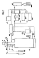
- FIG 2 there is shown an installation for continuously preparing sulfur fluorides of formula SF 6 and S 2 Fio.
- This installation comprises a photochemical reactor 1 produced for example in monel R or in nickel comprising at its upper part a window 2 transparent to radiation 4 coming from a source of ultraviolet radiation 5.
- the window can be made of crystalline fluoride, for example in calcium fluoride, barium fluoride, magnesium fluoride, lithium fluoride or fluoride glass.
- Sulfur tetrafluoride can be introduced into the reactor 1 from the source 7 of sulfur tetrafluoride through the line 9 provided with the valve 11 near the transparent window 2.
- Uranium hexafluoride can also be introduced into the reactor 1 near the window 2 from the source 13 via the pipe 15 provided with the valve 17.
- the photochemical reactor 1 is in communication with a stilling volume 19 whose dimensions are calculated to facilitate the coagulation of the solid products, either polymers of UF 5 or of other uranium fluorides like U 2 F 9 and UF 4 , which leave the reactor 1.
- These solid products are collected at the base of volume 19 and they can be evacuated by conventional means, not shown in the drawing.
- the pressure in the reactor can be controlled by a pressure gauge 21 placed on the volume 19 and the photochemical reactor 1 can be isolated from the volume 19 by means of a shutter 23.
- the gas mixture leaves volume 19 via line 25 and then passes through a filter 27 which makes it possible to stop the final submicron particles suspended in the gas mixture.
- the gases then exit the filter 27 via line 29 which directs them to a purification system constituted for example by a set of cold traps 33, 35, 37, 39 making it possible to separate and recover the desired sulfur fluoride (SF 6 or S 2 F 1 o).
- the analyzes carried out on the gaseous mixture leaving the filter via line 29 show that it generally consists of SF 4 , SFe, S 2 Fio and UF 6 .
- Sulfur sub-fluorides may also be present as impurities. Also, it is necessary to separate the fluoride S 2 Fio or SF 6 from the other constituents.
- the photochemistry is carried out in reactor 1 so that the SF 4 introduced is a minority compared to UF 6 .
- the gaseous mixture at line 29 will essentially consist of the product SF 6 with S 2 F i o and unreacted reagent UF 6 as well as possible traces of SF 4 and possibly fluorine from a defect of SF 4 at the end of the reaction.
- the separation of SF 6 from the other gases in the mixture is carried out by selective trapping of vapors of lower vapor pressure.
- the cold trap 33 stops the SF4 and the more easily condensable gases (S 2 Fio and UF 6 ). For this, the cold trap is maintained at a temperature of the order of 135 to 145 K at which the SF 6 has a vapor pressure of the order of 100 Pa. If necessary, a second cold trap 35 placed downstream and maintained at a temperature equal to or lower than the first will perform the same function and improve ra the efficiency of the gas separations undertaken.
- the SF 6 which remains gaseous in these cold traps is then evacuated to a purification system 41.
- the traces of SF 4 , F 2 , sulfur sub-fluorides, or even UF 6 can be easily retained by hydrolysis in an alkaline solution; the acid components -HF, F 2 - can be stopped by absorption; SF 6 is finally dried by condensation of water, either at low temperature, for example at 200 K, or by the action of a solid desiccant.
- the purified SF 6 can then be stored in the containers 43 by condensation at 77 K.
- the purification operation 41 is advantageously carried out on an additional assembly.
- SF 6 separation methods can be used for the separation of SF 6 from the gas mixture, such as gas chromatography or the specific reversible adsorption of SF 4 and UF 6 on adsorbent.
- Pressure gauges such as 21 are used to monitor pressures in various parts of the circuit; similarly flowmeters (not shown) measure the different gas flow rates.
- the gas mixture introduced will be predominantly in SF 4 , so that the UF 6 is largely exhausted at the outlet of the photochemical reactor 1.
- the gas mixture in the pipe 29 essentially consists of SF 4 and S 2 F 10 .
- the gases penetrate directly into the cold trap 33 for the separation operation between SF 4 and S 2 Fio.
- the temperature of the trap will advantageously be adjusted in the region of 170 to 180 K so that the S 2 F 10 is the only one trapped letting pass the SF 4 which is extracted by the gas extraction system 45.
- the purification of the S 2 F i o is then carried out as has been said for the SF e , after reheating of the cold trap 33.
- reference 47 represents an assembly making it possible to create a vacuum in the installation and to carry out a prior fluorination of its various parts.
- Reference 49 designates a pipe for introducing an additional neutral gas which is rigorously anhydrous under the inlet window 2.
- the neutral gas In the case where a collimated beam is used, it is possible to limit the rate of scanning by the neutral gas by keeping it locally in the region to be protected, that is to say by introducing it under overpressure and putting it in circulation by own entrances and exits.
- a diaphragm may be present in order to limit the leakage of the sweeping gas into the reaction part of the reactor and to ensure the passage of the beam possibly focused on this location.
- the extracted purging gas is directly reinjected under the optical window after having passed through a cold trap for retaining undesirable condensable vapors.
- a mechanical system for displacing the deposits formed thereon outside the lighting area To protect the window, it is also possible to use a mechanical system for displacing the deposits formed thereon outside the lighting area.
- a mixture of the following is introduced into the latter, closed at its lower part by the sealing device 23 SF 4 and UF 6 under partial pressures of 135 Pa in SF 4 and 405 Pa in UF ⁇ .
- the source of ultraviolet radiation 5 is constituted by a YAG: Nd3 + laser provided with a frequency doubler and quadruple delivering radiation at 266 nm, the diameter of the laser beam being 0.9 cm and the pulses having an energy radiating power of 5 mJ at a rate of 2 Hz.
- the average radiating power is 10 mW.
- the light source is a high-pressure mercury vapor lamp whose photons emitted around 245 nm are used over a width ⁇ of 45 nm , for which the energy flux is 100 mW, the beam having a diameter of 3 cm, which corresponds to a flux density in the reactor 1 of 14 mW.cm- 2 .
- the gas mixture of SF 4 and UF 6 introduced into the reactor has partial pressures of SF 4 and UF 6 such that the PSF 4 / PUF 6 ratio is equal to 1 and several tests are carried out by varying the partial pressure in UF 6 from 100 to 6000 Pa.
- the quantity of SF 6 produced increases with the partial pressure in UF 6 , the PSF e / PSF 4 ratio increasing by a few% to 50% when PUF 6 varies from 100 to 6000 Pa.
- the continuous preparation of SF 6 is carried out at room temperature in the installation of FIG. 2 using a photochemical reactor having a diameter of 3 cm and a length of 50 cm.
- a photochemical reactor having a diameter of 3 cm and a length of 50 cm.
- One operates under a partial pressure of 700 Pa of UF 6 by introducing the mixture SF 4 -UFs in the molar ratio 1/5, the mass flow rate of SF 4 being 2.3 g / h and that of UF 6 is 37 g / h.
- the CaF 2 window is swept by a stream of nitrogen, the flow rate of which is fixed at 10 g / h introduced in 49.
- a high-pressure xenon-mercury lamp emitting over the entire ultraviolet spectrum is used as the source of ultraviolet radiation 5.
- the continuous preparation of S 2 F 10 is carried out in the same installation as in Example 3.
- the reactants are introduced into the ratio SF 4 -UF 6 of 2/1, the pressure of UF 6 being 700 Pa , the mass flow rate of SF 4 of 6.5 g / h and that of UF 6 of 16 g / h.
- the reactants are introduced separately; SF 4 enters through valve 11 and serves as a purge gas to protect the CaF 2 window against deposits of UF S.
- the ultraviolet source being the xenon-mercury lamp operating under the conditions described in Example 3, the production of S 2 F l o at the outlet of the chemical reactor is established at 3.7 g / h, the SF 6 being present for less than one percent.
- the amorphous UF 5 solid does not retain sulfur as an impurity, it is produced at the rate of 9.5 g / h.
- FIG. 3 the installation shown in FIG. 3 is used.
- This installation is identical to that shown in FIG. 2 and therefore the same references have been used to designate the same constituents, but it also comprises an oven of pyrolysis 51 disposed on the pipe 29 leaving the filter 27 to convert the S 2 Fio to SF 6 .
- the mixture of SF 4 and UF 6 is put into circulation under the same flow and pressure conditions as those of Example 3 and a xenon-mercury high pressure lamp is also emitted emitting over the entire ultraviolet spectrum, of which l energy in the region of 215 to 300 nm arriving on the cell is evaluated at 4-5 W.
- the gases are introduced into the pyrolysis oven 51 brought to 210 ° C. and having a volume of 10 1 so as to convert the S 2 Fio into SFs. Under these conditions, 1.9 g / h of SF 6 and 9 g / h of ultra pure amorphous UF 5 are obtained.
- the temperature of the oven is chosen so that during the transit time of the mixture the majority of the S 2 Fio is decomposed. For example at 190 ° C. the half-reaction time of the disproportionation of S 2 F 10 under a partial pressure of a few thousand Pa is 4 min. Also, the controlled oven temperature is between 150 ° C and 300 ° C. In the case where the gas mixture at the outlet of the photochemical reactor contains gaseous fluorine, it will react easily with SF 4 according to the known reaction:
- the gas mixture in addition to SF 6 contains SF 4 and UF 6 which will be recycled through line 53.
- separation is carried out by the method known as dynamic fractional condensation, the principle in itself is well known.
- the first cold trap 33 preferentially stops the SF 4 and the more easily condesable gases such as the UF 6 and possibly the traces of S 2 F 10 , when its temperature is approximately 135 to 145 ° K.
- the second cold trap 35 improves capacity and increases efficiency of separation.
- the SF 6 gas in these traps is directed to storage 43 after purification as it was said previously.
- Heating the traps then allows the previously condensed vapors to become gaseous.
- these gases can be injected at the level of the flow valve 55 in quantities adapted to the needs by recycling line 53.
- the direct supplies of SF 4 and UF 6 through valves 11 and 17 will be reduced by the same amount.
- a photochemical reactor 1 is used, 1.5 cm in diameter and 10 cm in length, supplied with a mixture SF 4 -UF 6 in the ratio 1/3, the pressure in the reactor being 4000 Pa and the mass flows of SF 4 from UF 6 and N 2 being 45 g / h 450 g / h and 100 g / h respectively.
- the source of ultraviolet radiation is a pulsed KrF laser operating at the rate of 250 Hz and having an average power of 100 W which strictly illuminates the inlet window of the reactor after focusing.
- the production of SF 6 amounts to 25 g / h.
- the average speed of the reactants is approximately 150 cm / s. With the flow rates used, the mixing between the fresh reagents and the reaction products is avoided, which ensures good evacuation of the aerosol of UF s .
- the gaseous mixture leaving filter 27 is subjected to a pyrolysis treatment in a reactor having a volume of 10 l, heated to 210 ° C. Under these conditions, 43 g / h of SF 6 are obtained. and 200 g / h of chemically pure amorphous UFs.
- This example illustrates the use of heating the gas mixture in the photochemical reactor 1 to direct the reaction towards the production of sulfur hexafluoride SFs.
- the installation shown in FIG. 2 is used, but a thermostatic enclosure not shown in the drawing is added around the photochemical reactor 1 which allows the contents of the reactor to be brought to temperatures of 130 to 400 ° C.
- a copper photoreactor covered with a nickel deposit is used.
- a neutral gas such as nitrogen or argon is added, under a pressure of 2000 Pa to 5000 Pa via line 49, the neutral gas serving as protection for the window against deposits of UFs.
- a first continuous preparation test for sulfur hexafluoride is carried out using the flow and pressure conditions of Example 3, but by heating the photoreactor 1 to a temperature of 130 to 150 ° C. In these conditions, a higher concentration of sulfur hexafluoride is obtained at the outlet of the reactor than in example 3, of the order of 20 to 40%.
- the solid product collected at the base of volume 19 is rigorously pure crystallized UF 5 .
- the photochemical reaction is also carried out hot as in Example 7, oriented towards the production of SF 6 , but making it possible to reduce the UF 6 to a valence less than 5 in the form of U 2 F 9 .
- a first test the operation is carried out at a temperature of 200 ° C. in the closed reactor as in the second test of Example 7, but using a molar ratio SF 4 / UF 6 greater than that of this test. If a molar ratio of SF 4 / UF 6 greater than about 5/7 is adopted, there are two phases in the reaction. First of all, there is a rapid transformation of SF 4 into SF 6 which is all the more rapid the lower the initial UF 6 content and this practically until the exhaustion of the uranium hexafluoride gas . This first phase is followed by a slower kinetic reaction which is accelerated with temperature and which depends on the molar ratio SF 4 / UF 6 called m.
- the powder collected at the base of the closed reactor 1 is a crystallized solid identified on X-rays as a mixture of aUFs and U 2 F 9 .
- the photochemical reaction is carried out hot to produce SF 6 continuously as in Example 6, but using a gaseous mixture of SF 4 and UF 6 comprising an excess of SF 4 and a limited pressure of UFs , which in particular makes it possible to reduce the uranium hexafluoride to the form U 2 F 9 , of which it is known that the kinetics of the reaction are accelerated under low pressure of UF 6 and at high temperatures.
- the operation is carried out under the same conditions as above, but the reactor is heated to 400 ° C., which makes it possible to obtain a solid phase formed of crystals of U 2 F 9 and UF 4 . If the transit times of the photo-particles in the reactor is longer, the only stoichiometric UF 4 component is obtained, very pure. There is no pollution by sulfur or oxygen in the uranium fluoride thus obtained.
- the gas phase leaving the reactor is formed essentially of SF 6 with the exclusion of S 2 Fio.
- the installation of FIG. 2 is used with a photochemical reactor having a diameter of 0.7 cm and a length of 50 cm and a source of ultraviolet radiation constituted by a pulsed KrF laser which delivers pulses of 350 mJ at 249 nm.
- the beam is focused in the center of the reactor with a CaF 2 lens with a focal length of 1 m so that all of the gas mixture circulated in the reactor is irradiated.
- the pulse frequency is 100 Hz.
- the gaseous mixture of SF 4 and UFs is introduced in a proportion of 10/1 under 100 Pa of pressure into the photochemical reactor 1.
- the products leaving the reactor are formed essentially of S 2 F 10 and the uranium is mainly reduced to valence 4 in the form of UF 4 .
- This tetrafluoride comes either from the direct photodissociation of UF 6 with simultaneous departure of two fluorine atoms, or from the dissociation of gaseous monomer UFs or small polymers (UF 5 ) n .
- the gaseous monomeric uranium tetrafluoride can polymerize in a stable form and be collected in the solid state at the bottom of volume 19.
- the reactants circulating in the reactor 1 are subjected to irradiation by means of a first ultraviolet radiation at a wavelength of 266 nm to dissociate UF 6 and form highly excited gaseous UFs and second radiation at a wavelength of 532 nm to dissociate gaseous UF5 before collision.
- These radiations are obtained by the second and fourth harmonics of the 1.06 ⁇ m radiation supplied by a pulsed YAG laser: Nd 3 + whose pulse duration is 30 ns.
- the energy of ultraviolet radiation is 3 mJ, that of green light 80 mJ and the repetition frequency of shots 10 Hz.
- SF 4 and UF 6 are in slow flow in reactor 1 under a total pressure of 50 Pa. Under these conditions, mainly S 2 Fio is collected and the solid product is in the form of UF 4 and UFs which is in the majority.
- FIG. 2 the installation of FIG. 2 is used with a halogen lamp of 1000 W which has a continuous spectrum in the visible and emits weakly in the near ultraviolet.
- the beam is focused with a lens of 5 cm foval distance in the center of a photochemical reactor having an optical path of 2 cm.
- the gas mixture SF 4 and UF 6 in the ratio 10/1 circulates slowly in the reactor under a pressure of 100 Pa.
- the gases leaving the filter 27 essentially consist of S 2 Fio and the solid product collected at the base of volume 19 is UFs with traces of UF 4 .
- Examples 9 to 11 thus show the difficulty encountered in reducing photochemically UF 6 to valence 4, as the bond F 5 UF is relatively weak (70 Kcal) compared to the average bond energies of UF 6 (125 Kcal) and UF 4 (145 Kcal).
- This relatively low chemical stability of UF 6 explains its action as a strong fluorinating agent, leading for example to:
Landscapes
- Chemical & Material Sciences (AREA)
- Organic Chemistry (AREA)
- Inorganic Chemistry (AREA)
- Physics & Mathematics (AREA)
- Electromagnetism (AREA)
- Health & Medical Sciences (AREA)
- General Health & Medical Sciences (AREA)
- Toxicology (AREA)
- Chemical Kinetics & Catalysis (AREA)
- Geology (AREA)
- General Life Sciences & Earth Sciences (AREA)
- Optics & Photonics (AREA)
- Life Sciences & Earth Sciences (AREA)
- Inorganic Compounds Of Heavy Metals (AREA)
- Physical Or Chemical Processes And Apparatus (AREA)
- Organic Low-Molecular-Weight Compounds And Preparation Thereof (AREA)
Claims (22)
Applications Claiming Priority (2)
| Application Number | Priority Date | Filing Date | Title |
|---|---|---|---|
| FR8512623 | 1985-08-22 | ||
| FR8512623A FR2586410B1 (fr) | 1985-08-22 | 1985-08-22 | Procede de preparation de fluorures de soufre de formule s2f10 et sf6. |
Publications (2)
| Publication Number | Publication Date |
|---|---|
| EP0216664A1 EP0216664A1 (de) | 1987-04-01 |
| EP0216664B1 true EP0216664B1 (de) | 1990-07-18 |
Family
ID=9322343
Family Applications (1)
| Application Number | Title | Priority Date | Filing Date |
|---|---|---|---|
| EP19860401829 Expired - Lifetime EP0216664B1 (de) | 1985-08-22 | 1986-08-18 | Verfahren zur Herstellung von Dischwefeldekafluorid und Schwefelhexafluorid |
Country Status (3)
| Country | Link |
|---|---|
| EP (1) | EP0216664B1 (de) |
| DE (1) | DE3672728D1 (de) |
| FR (1) | FR2586410B1 (de) |
Families Citing this family (3)
| Publication number | Priority date | Publication date | Assignee | Title |
|---|---|---|---|---|
| FR2613348B1 (fr) * | 1987-04-02 | 1989-06-09 | Commissariat Energie Atomique | Procede de preparation de tetrafluorure, d'uranium par reduction d'hexafluorure d'uranium et fluorures de soufre obtenus par ce procede |
| DE3841209A1 (de) * | 1988-12-07 | 1990-06-13 | Siemens Ag | Verfahren zum herstellen von schwefelhexafluorid |
| CN114655982B (zh) * | 2022-04-07 | 2023-09-08 | 九江诺尔新材料科技有限公司 | 一种五氟化锑的连续生产方法及其应用 |
Family Cites Families (2)
| Publication number | Priority date | Publication date | Assignee | Title |
|---|---|---|---|---|
| DE2324779C3 (de) * | 1973-05-16 | 1978-07-06 | Kraftwerk Union Ag, 4330 Muelheim | Verfahren zur Trennung von gasförmigen Stoffgemischen unter Verwendung von Laserstrahlen |
| US3937956A (en) * | 1973-10-23 | 1976-02-10 | Exxon Research & Engineering Company | Isotope separation process |
-
1985
- 1985-08-22 FR FR8512623A patent/FR2586410B1/fr not_active Expired
-
1986
- 1986-08-18 DE DE8686401829T patent/DE3672728D1/de not_active Expired - Lifetime
- 1986-08-18 EP EP19860401829 patent/EP0216664B1/de not_active Expired - Lifetime
Also Published As
| Publication number | Publication date |
|---|---|
| DE3672728D1 (de) | 1990-08-23 |
| EP0216664A1 (de) | 1987-04-01 |
| FR2586410A1 (fr) | 1987-02-27 |
| FR2586410B1 (fr) | 1987-10-30 |
Similar Documents
| Publication | Publication Date | Title |
|---|---|---|
| EP0421834B1 (de) | Verfahren zur Auftragung einer amorphen anorganischen Schutzschicht auf ein polymeres organisches Substrat | |
| EP0129854A1 (de) | Verfahren und Vorrichtung zur Erzeugung von gasförmigen Produkten durch Zersetzung von Flüssigkeiten | |
| EP0216664B1 (de) | Verfahren zur Herstellung von Dischwefeldekafluorid und Schwefelhexafluorid | |
| Ikuta et al. | Defect formation and structural alternation in modified SiO 2 glasses by irradiation with F 2 laser or ArF excimer laser | |
| EP1262231B1 (de) | Verfahren zu selektiver Entfernung von funktionellen organischen Verbindungen aus einem Flüssigmedium | |
| WO1988000571A1 (fr) | Elimination catalytique de l'hydrogene sulfure de soufre liquide | |
| FR2976281A1 (fr) | Utilisation d'un compose kmgf3 pour pieger des metaux presents sous forme de fluorures et/ou d'oxyfluorures dans une phase gazeuse ou liquide | |
| FR2822853A1 (fr) | Preaparation de (mono) cristaux | |
| Brownsword et al. | Branching ratio for the H+ NCO channel in the 193 nm photodissociation of HNCO | |
| Fair et al. | The reaction of S (3P) atoms with molecular oxygen | |
| Izumi et al. | Irradiation Effects of Excimer Laser Light on Poly (vinylidene fluoride)(PVdF) Film. | |
| EP0073716A1 (de) | Verfahren zur Isotopentrennung durch Übertragung von Schwingungsenergie | |
| FR2597470A1 (fr) | Methode de purification des matieres premieres pour la fabrication de verre a chalcogenure | |
| JP3590048B1 (ja) | 同位体分離法および同位体分離用作業物質 | |
| EP0216663A1 (de) | Verfahren zur Herstellung von Schwefelhexafluorid | |
| FR2491771A1 (fr) | Procede de separation isotopique utilisant un faisceau laser | |
| Tsuji et al. | Photochemical Removal of SO2 and CO2 by 172 nm Xe2 and 146 nm Kr2 Excimer Lamps in N2 or Air at Atmospheric Pressure | |
| Kołos et al. | One-and two-photon laser photolysis of dicyanoacetylene | |
| Yoganarasimhan et al. | Photolysis of zinc azide in the solid state | |
| Xie et al. | UV photodissociation dynamics of the fumaronitrile molecule | |
| FR2598699A1 (fr) | Procede de preparation de tetrafluorure de soufre par reduction d'un fluorure d'uranium | |
| FR2526672A1 (fr) | Procede de separation isotopique de l'uranium utilisant une solution cryogenique | |
| EP0192514B1 (de) | Verfahren zur Herstellung von sehr reinem Zirkoniumtetrafluorid, verwendbar für die Erzeugung von Fluorglas | |
| WO1997038785A1 (en) | Metal fluorides separation | |
| JPH05251415A (ja) | 表面処理方法及び装置 |
Legal Events
| Date | Code | Title | Description |
|---|---|---|---|
| PUAI | Public reference made under article 153(3) epc to a published international application that has entered the european phase |
Free format text: ORIGINAL CODE: 0009012 |
|
| AK | Designated contracting states |
Kind code of ref document: A1 Designated state(s): DE GB IT NL |
|
| RAP1 | Party data changed (applicant data changed or rights of an application transferred) |
Owner name: COMMISSARIAT A L'ENERGIE ATOMIQUE |
|
| 17P | Request for examination filed |
Effective date: 19870903 |
|
| 17Q | First examination report despatched |
Effective date: 19881212 |
|
| GRAA | (expected) grant |
Free format text: ORIGINAL CODE: 0009210 |
|
| AK | Designated contracting states |
Kind code of ref document: B1 Designated state(s): DE GB IT NL |
|
| PG25 | Lapsed in a contracting state [announced via postgrant information from national office to epo] |
Ref country code: IT Free format text: LAPSE BECAUSE OF FAILURE TO SUBMIT A TRANSLATION OF THE DESCRIPTION OR TO PAY THE FEE WITHIN THE PRESCRIBED TIME-LIMIT;WARNING: LAPSES OF ITALIAN PATENTS WITH EFFECTIVE DATE BEFORE 2007 MAY HAVE OCCURRED AT ANY TIME BEFORE 2007. THE CORRECT EFFECTIVE DATE MAY BE DIFFERENT FROM THE ONE RECORDED. Effective date: 19900718 Ref country code: NL Effective date: 19900718 |
|
| REF | Corresponds to: |
Ref document number: 3672728 Country of ref document: DE Date of ref document: 19900823 |
|
| GBT | Gb: translation of ep patent filed (gb section 77(6)(a)/1977) | ||
| NLV1 | Nl: lapsed or annulled due to failure to fulfill the requirements of art. 29p and 29m of the patents act | ||
| PLBE | No opposition filed within time limit |
Free format text: ORIGINAL CODE: 0009261 |
|
| STAA | Information on the status of an ep patent application or granted ep patent |
Free format text: STATUS: NO OPPOSITION FILED WITHIN TIME LIMIT |
|
| 26N | No opposition filed | ||
| PGFP | Annual fee paid to national office [announced via postgrant information from national office to epo] |
Ref country code: DE Payment date: 19910724 Year of fee payment: 6 |
|
| PGFP | Annual fee paid to national office [announced via postgrant information from national office to epo] |
Ref country code: GB Payment date: 19910808 Year of fee payment: 6 |
|
| PG25 | Lapsed in a contracting state [announced via postgrant information from national office to epo] |
Ref country code: GB Effective date: 19920818 |
|
| GBPC | Gb: european patent ceased through non-payment of renewal fee |
Effective date: 19920818 |
|
| PG25 | Lapsed in a contracting state [announced via postgrant information from national office to epo] |
Ref country code: DE Effective date: 19930501 |